Table of Contents
Advertisement
Quick Links
OWNER'S MANUAL
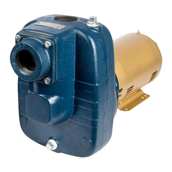
Turf Boss 3-5 HP
The Turf Boss is designed for applications moving
high volumes of water, such as timer-operated
irrigation systems, commercial dewatering, resi-
dential water transfer, rainwater drainage, light
agricultural irrigation, sump drainage, and indus-
trial liquid transfer. A premium self-priming
sprinkler pump, the Turf Boss is approved for
indoor or outdoor operation through CSA and UL.
This product is covered by a limited warranty for a period of 1 year from the date of original purchase by the
consumer. For complete warranty information, refer to www.FranklinWater.com.
Specifications
Pumps
Model
FTB3CI
FTB3CI-T
FTB3CI-E
FTB3CI-TE
FTB3CI-T5E
FTB5CI
FTB5CI-T
FTB5CI-E
FTB5CI-TE
FTB5CI-T5E
Pump Ends
Model
FTB3CI-PE
FTB5CI-PE
Suction x
HP
Discharge (in)
3
2 x 2
5
2½ x 2
Suction x
HP
Discharge (in)
3
2 x 2
5
2½ x 2
Motor
Phase
Enclosure
1
ODP
3
1
TEFC
3
1
ODP
3
1
TEFC
3
NEMA Motor Frame Size Fitment
143-184JM
4.5 AK
Volts
230
230/460
230
230/460
575
230
230/460
230
230/460
575
.875" Shaft
Advertisement
Table of Contents


Need help?
Do you have a question about the Turf Boss FTB3CI and is the answer not in the manual?
Questions and answers