Table of Contents

Related Manuals for HPE StoreFabric M-Series


Summary of Contents for HPE StoreFabric M-Series
- Page 1 HPE StoreFabric M-Series SN2000M Spectrum™ Based Ethernet Switch Systems Hardware User Manual Models: SN2700M, SN2410M/SN2410bM, SN2100M and SN2010M Rev 1.1 Part Number: P10784-001 Published: August 2018...
- Page 2 N o t i c e s © C o p y r ig h t 2 0 1 7 H e w le t t P a c k a r d E n t e r p r is e D e v e lo p m e n t L P T h e in f o r m a t io n c o n t a in e d h e r e in is s u b je c t t o c h a n g e w it h o u t n o t ic e.
-
Page 3: Table Of Contents
Table of Contents Chapter 1 Introduction to HPE StoreFabric M-Series SN2000M Spectrum™ Based Ether- net Switch Systems 12 1.1 Overview ........... . 12 1.2 Speed and Switching . - Page 4 3.2 LEDs ............59 3.2.1 LED Notifications .
- Page 5 List of Tables Table 1: Revision History Table ..........9 Table 2: References .
- Page 6 List of Figures Figure 1: SN2700M Front Side View ..........13 Figure 2: SN2410M/SN2410bM Front Side View .
- Page 7 Figure 36: Attached Rail with Threaded Cables - Top View ....... . . 38 Figure 37: Sliding the Frame Sliders into the Rails .
- Page 8 Figure 72: SN2010M SFP Port LEDs ........... . 67 Figure 73: SN2700M Pull-out Tab .
-
Page 9: Table 1: Revision History Table
Revision History Table 1 - Revision History Table Date Revision Description August 2018 Added the SN2010M systems to the User Manual Updated the following sections: • Section 3.1.1, “Data Interfaces,” on page 56 • Section 5.2, “Specifications,” on page 85 •... -
Page 10: Table 2: References
About this Manual This manual describes the installation and basic use of the HPE StoreFabric M-Series SN2xxxM systems. Intended Audience This manual is intended for IT managers and system administrators. References Table 2 - References Document Description MLNX-OS® User Man- This document contains information regarding the configuration and man- agement of the MLNX-OS software. - Page 11 This icon indicates a situation that can potentially cause damage to hardware or software. This icon indicates a situation that can potentially cause personal injury. This icon indicates a situation that can potentially cause personal injury. User Manual...
-
Page 12: Chapter 1 Introduction To Hpe Storefabric M-Series Sn2000M Spectrum™ Based Ether- Net Switch Systems
10, 25, 40, 50 and 100GbE in a large scale without changing power infrastruc- ture facilities. The Spectrum™ based 1U switch systems are a part of HPE StoreFabric M-Series’ complete end-to-end solution, which provides 10GbE through 100GbE interconnectivity within the data center. -
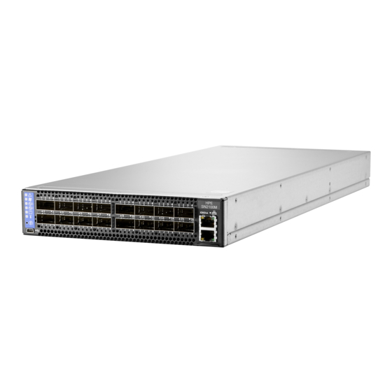
Page 13: Figure 1: Sn2700M Front Side View
Introduction to HPE StoreFabric M-Series SN2000M Spectrum™ Based Ethernet Switch Figure 1: SN2700M Front Side View Figure 2: SN2410M/SN2410bM Front Side View Figure 3: SN2100M Front Side View Figure 4: SN2010M Front Side View Figure 5: SN2700M and SN2410M/SN2410bM Rear Side View... -
Page 14: Speed And Switching
4 units (non- replaceable) replaceable) Features For a full feature list, please refer to the system’s product brief in HPE’s website: https:// www.hpe.com. Certifications The list of certifications (such as EMC, Safety and others) per system for different regions of the... -
Page 15: Ordering Information
Introduction to HPE StoreFabric M-Series SN2000M Spectrum™ Based Ethernet Switch https://www.hpe.com Ordering Information The following table lists ordering information for the available systems. Please pay attention to the airflow direction when ordering your system. For more details, see “Air Flow”. -
Page 16: Chapter 2 Installation
Installation Safety Warnings Prior to the installation, please review the safety warnings as follows: • For Nordic Countries Notices, see Section E.1, “Nordic Countries Notices,” on page • For Safety Warnings in English, see Section E.2, “Installation Safety Warnings (English),” on page •... -
Page 17: Air Flow
The following information does not apply to SN2100M/SN2010M. In the SN2100M/ SN2010M systems, the fan units are non-replaceable. All HPE StoreFabric M-Series switches have back-to-front air flow, as shown in Figure 8 All servers and systems in the same rack should be planned with the same airflow direction. -
Page 18: 19" Systems Mounting Options
A designated rail kit for the SN2100M/SN2010M systems can be purchased sepa- rately. If anything is damaged or missing, contact your HPE sales representative. 19” Systems Mounting Options By default, the SN2700M system is sold with the static rail kit described in Section 2.5.1. - Page 19 Installation Figure 9: Rack Rail Kit Parts To mount the system into the rack: Before mounting the system to the rack, select the way you wish to place the system. Pay atten- tion to the airflow within the rack cooling, connector and cabling options. While planning how to place the system, consider the two installation options shown in Figure 10, and review the following points:...
-
Page 20: Figure 10: Installation Options
Figure 10: Installation Options Attach the left and right rack mount rails (A) to the switch, by gently pushing the switch Step 1. chassis’ pins through the slider key holes, until locking occurs. Secure the chassis in the rails by screwing 2 flat head Phillips screws (E) in the designated Step 2. -
Page 21: Figure 12: Attaching The Brackets To The Chassis
Installation Figure 12: Attaching the Brackets to the Chassis Install 8 cage nuts in the desired 1U slots of the rack: 4 cage nuts in the non-extractable side Step 4. (in the top and bottom holes only) and 4 cage nuts in the extractable side. Figure 13: Installing the Cage Nuts While each rack U (unit) consists of three holes, the cage nut should be installed verti- cally with its ears engaging the top and bottom holes only. -
Page 22: Figure 14: Attaching The Brackets To The Rack
Figure 14: Attaching the Brackets to the Rack Slide the two blades into the left and right rails, and adjust them to fit your rack's depth. Use Step 6. four M6 screws (D) to fix the blades into the rack. Do not tighten the screws yet. Figure 15: Sliding the Blades in the Rails Secure the system in the rack by tightening the 8 screws inserted in Step 5 and Step 6 with a Step 7. -
Page 23: Telescopic Rail Kit For Sn2700M
Installation Remove the rails and brackets from the chassis by unscrewing 8 screws. Step 5. 2.5.2 Telescopic Rail Kit for SN2700M The Telescopic rail kit is not included in the system’s package, and can be purchased separately. There are two installation kit options: •... -
Page 24: Figure 16: Rack Rail Kit Parts
Figure 16: Rack Rail Kit Parts Figure 17: Rails Separation To separate the rails: 1. Extend the rail assembly by pulling the extension outwards (D). 2. Extract rail A from rail C by pushing it outside from the rear part of the assembly. To allow com- plete separation of rail A from rail C, press the quick-release latch. -
Page 25: Figure 18: Installing The Cage Nuts
Installation Before mounting the system to the rack, select the way you wish to place the system. Pay atten- tion to the airflow within the rack cooling, connector and cabling options. While planning how to place the system, review the following points: •... -
Page 26: Figure 20: Attaching The Inner Rails To The Chassis
Figure 20: Attaching the Inner Rails to the Chassis Secure the chassis in the inner rails by screwing the 2 flat head Phillips screws (F) in the Step 5. designated points with a torque of 1.5±0.2 Nm. Figure 21: Securing the Chassis in the Inner Rails Slide the switch into the rack by carefully pushing the inner rails into the outer rails installed Step 6. -
Page 27: Figure 22: Sliding The Switch Into The Rack
Installation Figure 22: Sliding the Switch into the Rack When fully inserted, fix the switch by closing the remaining 2 screws in the middle and Step 7. tightening the 8 screws inserted in Step 2 with a torque of 4.5±0.5 Nm. 2.5.2.1 Removing the System from the Rack ... -
Page 28: Figure 23: Pulling The Unit Outwards
Figure 23: Pulling the Unit Outwards Press on the locking spring (appears in red in Figure 24) on both sides simultaneously, and Step 4. continue pulling the unit towards you until it is fully removed. Figure 24: Locking Mechanism User Manual... -
Page 29: Static Rail Kit For Sn2410M/Sn2410Bm
Installation 2.5.3 Static Rail Kit for SN2410M/SN2410bM At least two people are required to safely mount the system in the rack. By default, the system is sold with the standard-depth rail kit. The short-depth rail kit can be supplied upon request. Table 8 - Installation Kit Kit OPN Rack Size and Rack Depth Range... -
Page 30: Figure 25: Rack Rail Kit Parts
Figure 25: Rack Rail Kit Parts Before mounting the system to the rack, select the way you wish to place the system. Pay atten- tion to the airflow within the rack cooling, connector and cabling options. While planning how to place the system, consider the two installation options shown in Figure 26, and review the following points: •... -
Page 31: Figure 26: Installation Options
Installation Figure 26: Installation Options Attach the left and right rack mount rails (A) to the switch, and secure the chassis in the rails Step 1. by screwing 2 flat head Phillips screws (D) in the designated points on each side (a total of 4 screws). -
Page 32: Figure 28: Installing The Cage Nuts
three holes, the cage nut should be installed vertically with its ears engaging the top and bot- tom holes only. See Figure Figure 28: Installing the Cage Nuts While your installation partner is supporting the system’s weight, perform steps 3, 4 and 5: On the rear side of the cabinet, install the two blades (B) in the selected rack unit, using four Step 3. -
Page 33: Side By Side Mounting For Sn2100M/Sn2010M Rail Kit
Installation Figure 30: Sliding the Blades in the Rails Secure the system in the rack by tightening the 8 screws inserted in Step 3 and Step 4 with a Step 5. torque of 4.5±0.5 Nm. 2.5.4 Side by Side Mounting for SN2100M/SN2010M Rail Kit The installation process is demonstrated on an SN2100M system, but applies to the SN2010M series as well. -
Page 34: Table 9: Installation Kit
Table 9 - Installation Kit Kit OPN Rack Size and Rack Depth Range Q2F25A Rack installation kit for SN2100M/SN2010M series short depth 1U switches, allows installation of one or two switches side-by-side into standard depth racks The following parts are included in the rail kit (see Figure 31): •... -
Page 35: Figure 31: Rack Rail Kit Parts
Installation Figure 31: Rack Rail Kit Parts Before mounting the system to the rack, select the way you wish to place the system. Pay atten- tion to the airflow within the rack cooling, connector and cabling options. • The installation kits come with enough system mounted rails and flat head screws to install two systems. -
Page 36: Figure 32: Coupling The Cables With Cable-Ties
frame’s left part, follow the same instructions, while replacing “right” with “left”, and vice versa. Insert the SE (single ended) plugs to the dedicated inlets in the system’s rear panel. Step 1. Carefully position the SE (single ended) cables one on top of the other, and use three cable- Step 2. -
Page 37: Figure 34: Cables Within The Rail
Installation Figure 34: Cables within the Rail In the next you will be attaching the rails to the chassis, before doing that, make sure the cables are laid properly within them. Avoid using excessive pressure, as it can damage the cables. While holding the cables stably together in the blade’s rail with one hand, use your other Step 4. -
Page 38: Figure 35: Attach The Blades To The System
Figure 35: Attach the Blades to the System Figure 36: Attached Rail with Threaded Cables - Top View Slide the two frame slides into the dedicated rails in the metal frame. See Figure Step 5. User Manual... -
Page 39: Figure 37: Sliding The Frame Sliders Into The Rails
Installation Figure 37: Sliding the Frame Sliders into the Rails Place the frame in the cabinet, and install ten cage nuts in the desired 1U slots of the rack: Step 6. three cage nuts in the front part of each cabinet post, and two cage nuts in the rear part of each cabinet post. -
Page 40: Figure 39: Attaching The Frame To The Rack
Figure 39: Attaching the Frame to the Rack Do not remove both of the blank covers at the same time. When no system is installed, at least one of them should be present to support the frame’s partition. Remove the blank cover from the selected slot in the frame, and mount the system by slid- Step 8. -
Page 41: Cable Installation
Installation Cable Installation All cables can be inserted or removed with the unit powered on. To insert a cable, press the connector into the port receptacle until the connector is firmly seated. The LED indicator, corresponding to each data port, will light when the physical connection is established. -
Page 42: Figure 42: Sn2010 Sfp Cable Orientation
Figure 42: SN2010 SFP Cable Orientation Figure 43: SN2410M/SN2410bM Cable Orientation User Manual... -
Page 43: Supported Modules And Cables
Installation 2.6.1 Supported Modules and Cables Table 10 - Supported Modules and Cables Supported QSFP28 Modules & Cables Supported SFP+/SFP28 Modules & Cables SN2700M • • SN2410M/ • • SN2410bM SN2100M • QSFP28, SFP28 short and long range • optics •... -
Page 44: Figure 44: Breakout Or Fanout Cables
Figure 44: Breakout or Fanout Cables 2.6.2.2 SN2700M Splitting Options Figure 45: SN2700M Splitting Options The top QSFP28 ports marked in green are splittable to 4 SFP28 ports, each. The bottom QSFP28 ports (gray) are blocked when the upper ports are in split mode. All QSFP28 ports marked in yellow can be split to 2 SFP28 ports. -
Page 45: Figure 46: Sn2410M/Sn2410Bm Splitting Options
Installation 2.6.2.3 SN2410M/SN2410bM Splitting Options Figure 46: SN2410M/SN2410bM Splitting Options The top QSFP28 ports - 49,51,53,55 (green) are splittable to 4 SFP28 ports each. All QSFP28 ports can be split into two SFP28 ports. The bottom QSFP28 ports - 50,52,54,56 (gray) are blocked when the upper ports are in split mode. -
Page 46: Initial Power On
Step 3. It may take up to five minutes to turn on the system. If the System Status LED shows red after five minutes, unplug the system and call your HPE representative for assis- tance. Check the System Status LEDs and confirm that all of the LEDs show status lights consis- Step 4. -
Page 47: Figure 48: System Status Leds 5 Minutes After Power On In Sn2700M
Installation Figure 48: System Status LEDs 5 Minutes After Power On in SN2700M Figure 49: System Status LEDs 5 Minutes After Power On in SN2410M/SN2410bM Figure 50: System Status LEDs 5 Minutes After Power On in SN2100M Figure 51: System Status LEDs 5 Minutes After Power On in SN2010M User Manual... -
Page 48: System Bring-Up
If no obstacles were found and the problem persists, call your HPE representative for assistance. Figure 52: Two Power Inlets - Electric Caution Notifications... -
Page 49: Table 11: Serial Terminal Program Configuration
Installation Configure a serial terminal program (for example, HyperTerminal, minicom, or Tera Term) Step 2. on your host PC with the settings described in Table 11. Once you perform that, you should get the CLI prompt of the system. Table 11 - Serial Terminal Program Configuration Setting Parameter Baud Rate... -
Page 50: Table 13: Configuration Wizard Session - Static Ip Configuration
Table 12 - Configuration Wizard Session Wizard Session Display Comments Step 6: Admin password (Press To avoid illegal access to the machine, please type a password <Enter> to leave unchanged)? and then press <Enter>. Then confirm the password by re-enter- <new_password>... - Page 51 Check the software version embedded in your system, using the command ‘show version’. Step 6. Compare this version to the latest version that can be retrieved from HPE support site. To upgrade software, please refer to the MLNX-OS User Manual.
- Page 52 2.8.1.1.1 Disable Dynamic Host Configuration Protocol (DHCP) DHCP is used for automatic retrieval of management IP addresses. If a user connects through SSH, runs the wizard and turns off DHCP, the connection is immediately terminated, as the management interface loses its IP address. <localhost># ssh admin@<ip-address>...
-
Page 53: Fru Replacements
Installation FRU Replacements The following information does not apply to the SN2100M/SN2010M series. The SN2100M/SN2010M systems include two non-replaceable power supply units and four non-replaceable fan units. 2.9.1 Power Supply The systems that are equipped with two replaceable power supply units work in a redundant con- figuration. -
Page 54: Fans
Figure 53: PS Unit Pulled Out To insert a power supply unit: Make sure the mating connector of the new unit is free of any dirt and/or obstacles. Step 1. Do not attempt to insert a power supply unit with a power cord connected to it. Insert the power supply unit by sliding it into the opening, until a slight resistance is felt. -
Page 55: Figure 54: Fan Module Latches
Installation Grasping the handle with your right hand, push the latch release with your thumb while Step 1. pulling the handle outward. As the fan unit unseats, the fan unit status LEDs will turn off. Remove the fan unit. Step 2. ... -
Page 56: Chapter 3 Interfaces
Interfaces Supported Interfaces The systems support the following interfaces: • Data interfaces - Ethernet • 10/100/1000 MbE speed rates • USB port (mini USB in SN2100M) • RS232 Console port • RJ45 management interface(s) • Reset button • Status and Port LEDs In order to review the full configuration options matrix, refer to Table 4, “Management Inter- faces, PSUs and... -
Page 57: Speed
Interfaces Figure 55: Using 4.5W Modules on Ports 49, 50, 55, 56 in SN2410M/SN2410bM 4.5W 4.5W Up to 1.5W Up to 1.5W 4.5W 4.5W Up to 1.5W Up to 1.5W 3.1.1.1 Supported Passive Cables in SN2010M • For server ports: •... -
Page 58: Rs232 (Console)
3.1.3 RS232 (Console) The port labeled “Console” is an RS232 serial port on the back side of the chassis in SN2700M, and SN2410M/SN2410bM, and on the front side in SN2100M/SN2010M. It is used for initial configuration and debugging. Upon first installation of the system, you need to connect a PC to this interface and configure network parameters for remote connections. -
Page 59: Reset Button
Interfaces 3.1.6 Reset Button The reset button is located on the rear side of the system next to the fan status LEDs in SN2700M and SN2410M/SN2410bM, and on the front side in SN2100M/SN2010M. This reset button requires a tool to be pressed. Do not use a sharp pointed object such as a needle or a push pin for pressing the reset button. -
Page 60: Figure 57: System Status Leds - Front And Rear Sides In Sn2700M
Table 15 - LEDs Symbols Normal Symbol Name Description Conditions Unit Identifier LED Lights up on command through the CLI. Off or blue when identifying a port a. There are two PSU LEDs in SN2100M/SN2010M. 3.2.1.1 System Status LED Figure 57: System Status LEDs - Front and Rear Sides in SN2700M Both of these LEDs in the red ovals show the system’s status. -
Page 61: Table 16: System Status Led Assignments
Both of the System Status LEDs (front and back, if exist) supply identical information. It may take up to five minutes to turn on the system. If the System Status LED shows red after five minutes, unplug the system and call your HPE representative for assis- tance. -
Page 62: Figure 61: Fan Status Led In Sn2700M - Front And Rear Sides
3.2.1.2 Fan Status LED Figure 61: Fan Status LED in SN2700M - Front and Rear Sides Both of these LEDs in the red ovals show the fans’ status. Figure 62: Fan Status LED in SN2410M/SN2410bM - Front and Rear Sides Both of these LEDs in the red ovals show the fans’... -
Page 63: Table 17: Fan Status Front Led Assignments
Interfaces Figure 64: Fan Status LED in SN2010 Table 17 - Fan Status Front LED Assignments Description Action Required Behavior Solid All fans are up and running. Green Solid Red Error, one or more fans are not operating prop- The faulty FRUs should be replaced. erly. -
Page 64: Figure 65: Power Status Led
3.2.1.3 Power Supply Status LEDs The following information does not apply to the SN2100M/SN2010M systems. In these systems, the power supply units are non-replaceable, and there is a designated LED for each unit in the system’s front panel. See Figure 3 Figure Figure 65: Power Status LED There are two power supply inlets in the system (for redundancy). -
Page 65: Table 20: Power Supply Unit Status Front Led Assignments For Sn2100M/Sn2010M
Plug in the AC cord of the faulty PSU. the second power supply still has AC input power. PS failure (including voltage out of range Check voltage. If OK, call your HPE representative for assistance. power cord disconnected). Flashing Amber... -
Page 66: Table 22: Bad Port Led Assignments
Table 22 - Bad Port LED Assignments LED Configuration Description Action Required No symbol errors have been received in last few seconds (normal condition). Flashing Amber Error, one or more ports have received sym- Check symbol error counters on the bol errors. -
Page 67: Table 23: Port Leds In Ethernet System Mode
Interfaces Figure 71: SN2010M QSFP Port LEDs Figure 72: SN2010M SFP Port LEDs In the SN2410M/SN2410bM systems, the status of each pair of adjacent QSFP28 ports is indi- cated by four LEDs, as shown in the picture above: • While the bottom LEDs signify the port status in regular condition, the upper LEDs operate only when the port is split. -
Page 68: Inventory Information
LED Behavior Description Action Required Flashing Amber A problem with the link. Check the cable, and replace it if needed. Inventory Information The system’s inventory parameters (such as Serial Number, Part Number, GUID and MAC address) can be extracted from the inventory pull-out tab on the lower right side of the front panel. -
Page 69: Figure 74: Sn2410M/Sn2410Bm Inventory Information Illustration
Interfaces Figure 74: SN2410M/SN2410bM Inventory Information Illustration Figure 75: SN2100M Pull-out Tab User Manual... -
Page 70: Figure 76: Sn2010M Pull-Out Tab
Figure 76: SN2010M Pull-out Tab User Manual... -
Page 71: Chapter 4 Software Management
Software and firmware updates are available from the HPE Support website. Check that your current revision is the latest one available on the HPE Support website. If you do not have the lat- est revision, upgrade your software using the CLI or the GUI. Copy the updated software to a known location on a remote server within the user’s LAN. -
Page 72: Chapter 5 Troubleshooting
Troubleshooting Troubleshooting Instructions Table 24 - Troubleshooting Problem Indicator Symptoms Cause and Solution LEDs System Status LED is Cause: blinking for more than MLNX-OS software did not boot properly and only 5 minutes firmware is running. Solution: Connect to the system via the console port, and check the software status. - Page 73 Troubleshooting Table 24 - Troubleshooting Problem Indicator Symptoms Cause and Solution System boot failure Software upgrade failed Solution: while using on x86 based systems • Connect the RS232 connector (CONSOLE) to a MLNX-OS laptop. • Push the system’s reset button. •...
-
Page 74: Chapter 6 Specifications
Specifications SN2700M Series Table 25 - SN2700M Specifications Feature Value Mechanical Size: Standard - 1.72” (H) x 16.84” (W) x27” (D), 43.8mm (H) x 427.83mm (W) x 686.8mm (D) Mounting: 19” Rack mount Mounting: 19” Rack mount Weight: 1 PSU: 10.23kg, 2 PSUs: 11.1kg Speed: 10/25/40/50/56/100GbE per port Connector cage: 32 QSFP28 Environmental... -
Page 75: Sn2410M/Sn2410Bm Series
Specifications SN2410M/SN2410bM Series Table 26 - SN2410M/SN2410bM Specifications Feature Value Mechanical Size: 43.8mm (H) x 438mm (W) x 436mm (D) 1.72"(H) x 17.24"(W) x 17"(D) Mounting: 19" Rack mount Weight: 2 PSUs: 8.52kg Speed: 10/25GbE per port (ports 1-48), 10/25/40/50/56/100GbE per port (ports 49-56) Connector cage: 48xSFP28 and 8xQSFP28 Environmental Temperature:... -
Page 76: Sn2100M Series
SN2100M Series Table 27 - SN2100M Specifications Feature Value Mechanical Size: 43.8mm (H) x 200mm (W) x 508mm (D) 1.72" (H) x 7.87" (W) x 20" (D) Mounting: 19" Rack mount Weight: 4.540kg Speed: 10/25/40/50/56/100GbE per port Connector cage: 16xQSFP28 Environmental Temperature: Operational: 0°... -
Page 77: Sn2010M Series
Specifications SN2010M Series Table 28 - SN2010M Specifications Feature Value Mechanical Size: 43.8mm (H) x 200mm (W) x 508mm (D) 1.72" (H) x 7.87" (W) x 20" (D) Mounting: 19" Rack mount Weight: 4.500kg Speed: 10/25/40/50/56/100GbE per port Connector cage: 18 ports of 10/25GbE and 4 splittable ports of 40/100GbE Environmental Temperature: Operational: 0°... - Page 78 Table 28 - SN2010M Specifications Feature Value Power Input Voltage: 100-127VAC 50/60Hz 4.5A; 200-240 50/60Hz 2.9A Global Power Consumption: Typical power with passive cables (ATIS): 57W Max power with optical cables (assuming 3.5W per each QSFP28 port): 250W User Manual...
-
Page 79: Table 29: Opns For Replacement Parts
Appendix A: Accessory and Replacement Parts Table 29 - OPNs for Replacement Parts Supported Part Description Notes Systems MTEF-KIT-A Rack installation kit for 1U systems to be mounted SN2700M Included in the into short or standard depth racks SN2700M pack- age. - Page 80 Appendix B: Thermal Threshold Definitions There are three thermal threshold definitions for the switch device which impact the overall switch system operation state: • Warning – 105°C: On managed systems only: When the device crosses the 100°C threshold, a Warning Threshold message will be issued by the management SW, indicat- ing to system administration that the switch has crossed the Warning threshold.
-
Page 81: Table 30: Qsfp Interface Pins 1-23
Appendix C: Interface Specifications SFP28 Interface Table 30 - QSFP Interface Pins 1-23 Connec Connect tor Pin or Pin Signal Description Numbe J3 and J6 Name J3 and J6 Ground Rx1n Rx1n Rx2n Rx2n Rx1p Tx2n Transmitter Inverted Data Input Rx2p Rx2p Rx1p... -
Page 82: Table 31: Qsfp Interface Pins 24-38
Table 31 - QSFP Interface Pins 24-38 Connector Connector Signal Description Pin Name Number Receiver Inverted Data Output 3 Rx4n Receiver Non-Inverted Data Output 3 Rx4p Ground ModPrsL Module Present Interrupt IntL +3.3 V Power supply transmitter Vcc Tx Vcc 1 +3.3 V Power Supply LPMode Low Power Mode... -
Page 83: Figure 77: Rear View Of Module With Pin Placement
SFP28 Interface 56.50 13.90 Mellanox Technologies 11.85 13.60 14.80 13.70 MTSFPP-SR Module 1.55 0.50 8.50 0.60 2.55 1.80 44.95 Figure 77: Rear View of Module With Pin Placement 13.70 8.50 User Manual... - Page 84 Symbol Name Description VeeT Transmitter Ground (Common with Receiver Ground) TX_Fault Transmitter Fault. TX_Disable Transmitter Disable. Laser output disabled on high or open. 2-wire Serial Interface Data Line 2-wire Serial Interface Clock Line MOD_ABS Module Absent. Grounded within the module No connection required RX_LOS Loss of Signal indication.
-
Page 85: Figure 78: Rj45 To Db9 Harness Pinout
RJ45 to DB9 Harness Pinout In order to connect a host PC to the Console RJ45 port of the system, a RS232 harness cable (DB9 to RJ45) is supplied. Figure 78: RJ45 to DB9 Harness Pinout User Manual... - Page 86 (EEE) should be collected separately and not disposed of with regular household waste. Dispose of this product and all of its parts in a responsible and environmentally friendly way. Follow the instructions found at https://www.hpe.com for proper disassembly and disposal of the switch, according to the WEEE directive. User Manual...
- Page 87 Appendix E: Safety Warnings (Multiple Languages) Nordic Countries Notices In Finland: "Laite on liitettävä suojakoskettimilla varustettuun pistorasiaan" In Norway: "Apparatet må tilkoples jordet stikkontakt" In Sweden: "Apparaten skall anslutas till jordat uttag" Installation Safety Warnings (English) 1. Installation Instructions Read all installation instructions before connecting the equipment to the power source. 2.
- Page 88 6. Stacking the Chassis The chassis should not be stacked on any other equipment. If the chassis falls, it can cause bodily injury and equipment damage. 7. Redundant Power Supply Connection - Electrical Hazard This product includes a redundant power or a blank in its place. In case of a blank power supply, do not operate the product with the blank cover removed or not securely fastened.
- Page 89 14. Equipment Disposal Disposal of this equipment should be in accordance to all national laws and regula- tions. 15. Local and National Electrical Codes This equipment should be installed in compliance with local and national electrical codes. 16. Installation Codes This device must be installed according to the latest version of the country national electrical codes.
- Page 90 21. Overcurrent Protection A readily accessible Listed branch circuit overcurrent protective device rated 20 A must be incorporated in the building wiring. 22. Do Not Use the Switch as a Shelf or Work Space Caution: Slide/rail mounted equipment is not to be used as a shelf or a work space. The rails are not intended for sliding the unit away from the rack.
- Page 91 חבלת גוף כתוצאה מנשיאת משקל יתר .נדרשת נוכחותם של מספר מתקינים כדי להרים את המוצר בבטחה <40 lbs 70 - 121 lbs >121 lbs 40 - 70 lbs <18 kgs 32 - 55 kgs >55 kgs 18 - 32 kgs ציוד...
- Page 92 !בעת סופות ברקים - סכנת התחשמלות בעת סופות ברקים, אין להפעיל את המערכת או לחבר/לנתק כבלים חיבור או ניתוק של כבלי נחושת כבלי נחושת הם כבדים וקשיחים. לפיכך, יש לחברם ולנתקם מהמחברים בזהירות .רבה. לאזהרות נוספות, יש לעיין בעלון לצרכן מטעם יצרן הכבלים הרכבה...
- Page 93 תקנות התקנה יש להתקין מערכת זו על פי הגרסה האחרונה של תקנות החשמל המקומיות הנהוגות במדינה. עבור צפון אמריקה, יש להתקין את המערכת בהתאם לתקנות החשמל הלאומיות .המיושמות בארה”ב ובקנדה חיבור בין מערכות מסוג להיות בעלי הסמכת Ethernet -ו RS232 על...
- Page 94 安裝安全性警告 (Chinese) 1. 安裝指示 本設備附有備援電源供應器或在適當位置配有空白蓋板。 2. 因重量導致的人身受傷 為了安全起見,請安排足夠的人員以合力抬起本產品。 <40 lbs 70 - 121 lbs >121 lbs 40 - 70 lbs <18 kgs 32 - 55 kgs >55 kgs 18 - 32 kgs 3. 重設備 本設備極重,應使用機械式起重機來搬移,以避免人員受傷。 4. 有觸電的危險 有觸電的危險! 拆除風扇模組後,即可接觸到模組空腔內的電源針腳。 請勿將工具或機身零件插入到風扇模組空腔內。 5.
- Page 95 7. 複式電源連接時的電擊危險 本設備附有備援電源供應器或在適當位置配有空白蓋板。如果是電源供應器空 白蓋板,在空白蓋板已取下或未牢牢固訂的情況下,請勿操作本產品。 8. 雙極 / 中性保險絲 本系統具有雙極 / 中性保險絲。請拔掉所有電源線後,再打開本產品的蓋板或 碰觸任何內部零件。 9. 多電源輸入座 電擊與能源危害的危險。 所有 PSU 均各自獨立。 將所有電源供應器斷電,確保交換器平台內部在電源關閉狀態。 10. 閃電時的電擊危險 在閃電期間,不要使用本設備或連接或拔下纜線。 11. 機架安裝與維修 此產品已安裝在機架中或在機架中維修時,必須採取特定預防措施以確保系統 維持穩定。一般您應該將設備從底部到頂端放滿機架。 12. 設備安裝 本設備僅限由經過訓練與 / 或合格的人員安裝、更換或維修。 13. 設備棄置 棄置本設備應遵照所有國內法規。 14. 當地與國家電氣法規 請遵照當地與國家電氣法規安裝本設備。 User Manual...
- Page 96 15. 安裝法規 請務必遵循最新版的國家電氣法規,安裝本設備。在北美地區,請務必遵循美 國國家電工法規和加拿大電工法規中的適用規定,安裝本設備。 16. 更換電池 警告:只能以 UL 認可電池,且取得最大異常充電電流低於 4mA 認證的電池進 行更換。 若更換錯誤類型的電池,會有爆炸的危險。 請依據指示棄置廢電池。 17. UL 列名和 CSA 認證電源線 北美地區在接上電源時,請選用獲得 UL 列名和 CSA 認證、三個導體、[16 AWG] 附成型插頭,額定值為 125 V、[13 A],長度至少 1.5 公尺 [ 六英尺 ],但 不超過 4.5 公尺的電源線。 歐洲地區在接上電源時,請選用國際協調式且標示有 <HAR> 字樣、三個導體、 標稱截面至少...
- Page 97 22. WEEE 指令 根據 WEEE 指令 2002/96/EC,所有廢棄的電氣與電子設備 (EEE),應分開集 中,而且不應與一般家庭廢棄物一起棄置。 請以負責和環保的方式棄置本產品及其所有零件。 23. 挪威國家電源限制 本設備僅限連接至挪威的 TN 電源系統和 IT 電源系統。 User Manual...
- Page 98 24. China CCC Warning Statement 25. Taiwan BSMI Class A Statement - Warning to the User! User Manual...
- Page 99 Avertissements de sécurité pour l'installation (French) 1. Instructions d'installation Veuillez lire la totalité des instructions d'installation avant de relier l'équipement au secteur. 2. Blessures à cause du poids Prévoyez assez de personnel pour soulever ce produit en toute sécurité. <40 lbs 70 - 121 lbs >121 lbs 40 - 70 lbs...
- Page 100 7. Connexion de l'alimentation redondante : danger d'électrocution Ce produit est équipé d'une alimentation redondante ou d'un cache si elle est absente. Dans ce dernier cas, ne pas faire fonctionner le produit si le cache est retiré ou mal fixé. 8.
- Page 101 15. Codes électriques locaux et nationaux Cet équipement doit être installé conformément aux codes électriques locaux et nation- aux. 16. Codes d'installation Cet appareil doit être installé conformément à la version la plus récente des codes élec- trique nationaux. En Amérique du Nord, l'équipement doit être installé en respectant les exigences de l'US National Electrical Code et du Code canadien de l'électricité.
- Page 102 22. Ne pas utiliser comme étagère ou plan de travail Attention : un équipement coulissant ou monté sur rail ne doit pas servir d'étagère ni de plan de travail. Les rails ne sont pas destinés à faire coulisser l'unité hors du rack. Ils sont destinés à...
- Page 103 3. Schweres Gerät Dieses Gerät ist schwer und muss mit einem mechanischen Hebegerät verschoben werden, um Verletzungen zu vermeiden. 4. Stromschlagrisiko Stromschlagrisiko! Bei abgenommenem Ventilatormodul sind die Stromkontakte in der Modulvertiefung zugänglich. Es dürfen KEINE Werkzeuge oder Körperteile in die Vertiefung des Ventilatormoduls gelangen.
- Page 104 10. Anschließen/Trennen von Kupferkabel Kupferkabel sind schwer und nicht flexible. Deshalb müssen sie vorsichtig an die Anschlüsse angebracht bzw. davon getrennt werden. Lesen Sie die speziellen Warnun- gen und Anleitungen des Kabelherstellers. 11. Rack-Montage und Wartung Wenn dieses Produkt in einem Rack montiert oder gewartet wird, sind besondere Vor- sichtsmaßnahmen zu ergreifen, um die Stabilität des Systems zu gewährleisten.
- Page 105 17. UL- und CSA-zertifiziertes Netzkabel Für Nordamerika Stromanschluss, wählen Sie ein Netzkabel, das UL-und CSA Certi- fied 3 - Leiter, [18 AWG], mit einem angespritztem Stecker bewertet bei 125 V, [15], mit einer Mindestlänge von 1,5 m [Six Feet] aber nicht mehr als 4,5 m. Für die europäischen Zusammenhang, wählen Sie ein Netzkabel, das international harmonisiert und der Aufschrift "<HAR>", 3 - Leiter, mindestens 0,75 mm2 Draht, bewertet mit 300 V, mit einem PVC-Mantel...
- Page 106 Advertencias de seguridad de instalación (Spanish) 1. Instrucciones de instalación Antes de conectar el equipo a la fuente de alimentación, leer todas las instrucciones de instalación. 2. Lesión corporal a causa de peso Recurra a suficientes personas para levantar este producto sin <40 lbs 70 - 121 lbs >121 lbs...
- Page 107 7. Conexión redundante de fuente de alimentación: peligro de descarga Este producto incluye una fuente de alimentación redundante o, en su lugar, una vacía. Si se dispone de una fuente de alimentación vacía, no utilizar el producto si su tapa está...
- Page 108 14. Eliminación del equipo La eliminación definitiva de este equipo se debe efectuar conforme a todas las leyes y reglamentaciones nacionales. 15. Códigos eléctricos locales y nacionales Este equipo se debe instalar conforme a los códigos eléctricos locales y nacionales. 16.
- Page 109 21. Interconexión de unidades Los cables para la conexión con las interfaces RS232 y Ethernet de la unidad deben estar homologados por UL tipo DP-1 o DP-2. (Nota: cuando residen en circuito no de tipo LPS) Protección contra sobrecargas: Al cableado del edificio se debe incorporar un disposi- tivo de protección contra sobrecargas de circuito derivado, de fácil acceso, con una corriente nominal de 20 A.
- Page 110 3. Тяжелое оборудование Это тяжелое оборудование, поэтому его следует перемещать с помощью механического подъемника во избежание травм. 4. Опасность поражения электрическим током Опасность поражения электрическим током! Когда снят вентиляторный модуль, существует возможность повреждения контактов питания в его углублении. НЕ вставлять инструменты или части тела в углубление вентиляторного модуля. 5.
- Page 111 10. Опасность поражения электрическим током во время грозы Во время грозы запрещается использовать оборудование и подключать или отключать кабели. 11. Подсоединение и отсоединение медных кабелей Медные кабели тяжелые и негибкие, поэтому следует осторожно их подсоединять и отсоединять. За особыми предупреждениями и указаниями следует...
- Page 112 17. Замена аккумулятора Осторожно! Заменять только аккумулятором, одобренным организацией UL и рассчитанным на максимальный аномальный зарядный ток не менее 4 мА. Существует риск взрыва при замене аккумулятора другим аккумулятором неправильного типа. Отработавшие аккумуляторы утилизируются в соответствии с указаниями. 18. Шнур питания, включенный в номенклатуру UL и сертифицированный Канадской ассоциацией...
- Page 113 23. Директива WEEE В соответствии с Директивой 2002/96/EC (WEEE) отходы электрического и электронного оборудования должны собираться и утилизироваться отдельно от обычных бытовых отходов. Следует утилизировать это изделие и все его части ответственным и экологически безопасным способом. Avertismente privind siguranţa la instalare (Romanian) 1.
- Page 114 Temperatură în exces Acest echipament nu trebuie să fie acţionat într-o zonă unde temperatura ambiantă depăşeşte valoarea maximă recomandată: 45°C (113°F). În plus, pentru a asigura un flux de aer adecvat, lăsaţi un spaţiu liber de cel puţin 8 cm (3 inchi) în jurul fantelor de ventilare.
- Page 115 13. Instalarea echipamentului Acest echipament trebuie să fie instalat, înlocuit şi/sau depanat numai de către personal instruit şi calificat. 14. Eliminarea echipamentului Eliminarea acestui echipament trebuie să se realizeze în conformitate cu toate legile şi regulamentele naţionale. 15. Codurile electrice locale şi naţionale Acest echipament trebuie să...
- Page 116 20. Codurile de instalare Acest dispozitiv trebuie să fie instalat în conformitate cu ultima versiune a codurilor electrice naţionale ale ţării în cauză. Pentru America de Nord, echipamentul trebuie să fie instalat conform cerințelor aplicabile din Codul electric naţional al SUA şi Codul electric canadian.
- Page 117 2. Tjelesne ozljede uslijed težine Kako biste sigurno podignuli ovaj proizvod, koristite dovoljan broj ljudi. <40 lbs 70 - 121 lbs >121 lbs 40 - 70 lbs <18 kgs 32 - 55 kgs >55 kgs 18 - 32 kgs Teška oprema Ova oprema je vrlo teška i treba se premještati pomoću mehaničkog dizala kako bi se izbjegle ozljede.
- Page 118 9. Višestruki ulazi za napajanje Rizik od strujnog udara i opasnost od električne energije. PSU jedinice su neovisne. Odspojite sva napajanja kako biste osigurali stanje bez napajanja unutar platforme preklopnika. 10. Tijekom udara munje - Opasnost od električne energije Tijekom djelovanja munja, nemojte raditi na opremi ili spajati ili odspajati kabele. 11.
- Page 119 17. Zamjena baterije Upozorenje: Bateriju zamijenite samo baterijom iz serije UL koja je certificirana za maksimalnu nepravilnu struju punjenja ne manju od 4 mA Postoji rizik od eksplozije ako se baterija zamijeni neodgovarajućom vrstom. Odložite prazne baterije sukladno uputama. 18. UL CSA kabel napajanja Za sjevernoameričku mrežu odaberite kabel napajanja koji je na UL listi i sa CSA cer- tifikatom, 3 - žilni, [16 AWG] (16 AWG) koji završava lijevanim utikačem nazivnog napona od 125 V, [13 A], minimalne duljine od 1,5 m [six feet] (šest stopa), ali ne dulji...
- Page 120 23. WEEE direktiva Sukladno WEEE direktivi 2002/96/EZ, sav električni i elektronički otpad (EEE) trebao bi se prikupljati zasebno i ne bi se trebao odlagati kao običan kućanski otpad. Odlaganje ovog proizvoda i svih njegovih dijelova vršite na odgovoran i ekološki način.
- Page 121 4. Rischio di scosse elettriche! Rischio di scosse elettriche! Con il modulo ventola rimosso, i pin di alimentazione sono accessibili all’interno della cavità del modulo. NON inserire strumenti o parti del corpo nella cavità del modulo della ventola. 5. Temperatura eccessiva Questa apparecchiatura non va utilizzata in un’area con una temperatura ambiente superiore a quella massima consigliata: 45 °C (113 °F).
- Page 122 11. Collegamento/scollegamento del cavo di rame I cavi di rame sono pesanti e non flessibili. Di conseguenza, vanno collegati o scollegati con cura dai connettori. Per avvertenze/istruzioni speciali, rivolgersi al produttore di cavi. 12. Montaggio su rack e manutenzione Quando questo prodotto viene montato o sottoposto a manutenzione su un rack, è necessario adottare delle precauzioni speciali per assicurarsi che il sistema resti stabile.
- Page 123 18. Cavo di alimentazione UL e munito di certificazione CSA Per una connessione di alimentazione nordamericana, selezionare un cavo di alimentazione di tipo UL e munito di certificazione CSA, a 3 conduttori, [16 AWG], terminato con una spina stampata con tensione nominale pari a 125 V, [13 A], di lunghezza minima pari a 1,5 m [sei piedi] ma non più...
- Page 124 24. Limitazioni relative all’alimentazione per la Norvegia Questa apparecchiatura è progettata esclusivamente per il collegamento a un sistema di alimentazione TN e a un sistema di alimentazione IT. E.12 Montaj Güvenlik Uyarıları (Turkish) 1. Montaj Talimatları Ekipmanı güç kaynağına bağlamadan önce tüm montaj talimatlarını okuyun. 2.
- Page 125 6. Şasi İstif Şasinin diğer herhangi bir ekipmanın üzerine istiflenmemesi gerekir. Şasi düşerse, fiziksel yaralanmalara ve ekipmanda hasara neden olabilir. 7. Yedekli Güç Kaynaðý Baðlantýsý -Elektrik Çarpma Tehlikesi Bu ürün, yedekli güç kaynağı veya onun yerine boş elektrik kutusu içerir. Güç kaynağı için boş...
- Page 126 14. Yerel ve Ulusal Elektrik Kodları Bu ekipmanın montajında yerel ve ulusal elektrik kodlarına uyulması gerekir. 15. Montaj Kodları Bu cihazın, ülke ulusal elektrik kodlarının son sürümüne göre monte edilmesi gerekir. Kuzey Amerika için, ekipmanın ABD Ulusal Elektrik Kodu ve Kanada Elektrik Kodu'nun uygulama koşullarına göre monte edilmesi gerekir.
- Page 127 21. Anahtarı Raf veya Çalışma Alanı olarak kullanmayınl Dikkat: Sürgülü/raylı ekipman raf veya çalışma alanı olarak kullanılamaz. Raylar üniteyi iskeleden uzağa kaydırmak için yapılmamıştır. Sadece, ekipmanın son olarak duracağı yerdeki kalıcı montaj içindir, servis veya bakım için kullanılamaz. 22. WEEE Yönergesi WEEE Yönergesi 2002/96/EC uyarınca, tüm elektrikli ve elektronik ekipman atıkları...
- Page 128 Support and other resources Accessing Hewlett Packard Enterprise Support • For live assistance, go to the Contact Hewlett Packard Enterprise Worldwide website: http://www.hpe.com/assistance • To access documentation and support services, go to the Hewlett Packard Enterprise Support Center website: http://www.hpe.com/support/hpesc Information to collect •...
- Page 129 Important: Access to some updates might require product entitlement when accessed through the Hewlett Packard Enterprise Support Center. You must have an HPE Passport set up with relevant entitlements. Customer self repair Hewlett Packard Enterprise customer self repair (CSR) programs allow you to repair your prod- uct.
- Page 130 To view the warranty for your product or to view the Safety and Compliance Information for Server, Storage, Power, Networking, and Rack Products reference document, go to the Enterprise Safety and Compliance website: www.hpe.com/support/Safety-Compliance-EnterpriseProducts Additional warranty information HPE ProLiant and x86 Servers and Options www.hpe.com/support/ProLiantServers-Warranties HPE Enterprise Servers www.hpe.com/support/EnterpriseServers-Warranties HPE Storage Products www.hpe.com/support/Storage-Warranties...
- Page 131 Hewlett Packard Enterprise is committed to providing documentation that meets your needs. To help us improve the documentation, send any errors, suggestions, or comments to Documentation Feedback (docsfeedback@hpe.com). When submitting your feedback, include the document title, part number, edition, and publication date located on the front cover of the document. For online help content, include the product name, product version, help edition, and publication date located on the legal notices page.
Need help?
Do you have a question about the StoreFabric M-Series and is the answer not in the manual?
Questions and answers