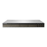
Sign In
Upload
Manuals
Brands
HPE Manuals
Network Router
SN2700M
HPE SN2700M Manuals
Manuals and User Guides for HPE SN2700M. We have
2
HPE SN2700M manuals available for free PDF download: Hardware User Manual
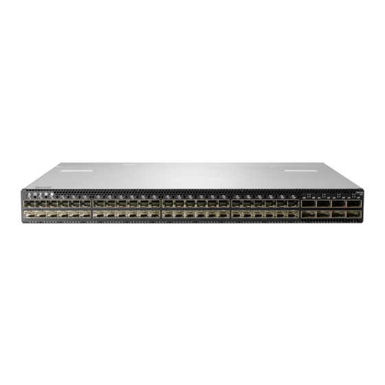
HPE SN2700M Hardware User Manual (131 pages)
Spectrum Based Ethernet Switch Systems
Brand:
HPE
| Category:
Switch
| Size: 5.67 MB
Table of Contents
Table of Contents
3
Table 1: Revision History Table
9
Table 2: References
10
Chapter 1 Introduction to HPE Storefabric M-Series SN2000M Spectrum™ Based Ether- Net Switch Systems
12
Overview
12
Figure 1: SN2700M Front Side View
13
Figure 2: Sn2410M/Sn2410Bm Front Side View
13
Figure 3: SN2100M Front Side View
13
Figure 4: SN2010M Front Side View
13
Figure 5: SN2700M and Sn2410M/Sn2410Bm Rear Side View
13
Figure 6: SN2100M Rear Side View
13
Figure 7: SN2010M Rear Side View
13
Speed and Switching
14
Management Interfaces, Psus and Fans
14
Features
14
Certifications
14
Table 3: Speed and Switching Capabilities
14
Table 4: Management Interfaces, Psus and Fans
14
Ordering Information
15
Table 5: Ordering Part Numbers (Opns)
15
Chapter 2 Installation
16
Safety Warnings
16
System Installation and Initialization
16
Air Flow
17
Package Contents
17
Figure 8: Air Flow Direction Marking - Power Side Inlet to Connector Side Outlet
17
19" Systems Mounting Options
18
Static Rail Kit for SN2700M
18
Table 6: Installation Kit
18
Figure 10: Installation Options
20
Figure 11: Attaching the Rails to the Chassis
20
Figure 12: Attaching the Brackets to the Chassis
21
Figure 13: Installing the Cage Nuts
21
Figure 14: Attaching the Brackets to the Rack
22
Figure 15: Sliding the Blades in the Rails
22
Telescopic Rail Kit for SN2700M
23
Table 7: Installation Kit
23
Figure 16: Rack Rail Kit Parts
24
Figure 17: Rails Separation
24
Figure 18: Installing the Cage Nuts
25
Figure 19: Mounting the Outer Rails into the Rack
25
Figure 20: Attaching the Inner Rails to the Chassis
26
Figure 21: Securing the Chassis in the Inner Rails
26
Figure 22: Sliding the Switch into the Rack
27
Figure 23: Pulling the Unit Outwards
28
Figure 24: Locking Mechanism
28
Static Rail Kit for Sn2410M/Sn2410Bm
29
Table 8: Installation Kit
29
Figure 25: Rack Rail Kit Parts
30
Figure 26: Installation Options
31
Figure 27: Attaching the Rails to the Chassis
31
Figure 28: Installing the Cage Nuts
32
Figure 29: Attaching the Rails to the Rack
32
Side by Side Mounting for SN2100M/SN2010M Rail Kit
33
Figure 30: Sliding the Blades in the Rails
33
Table 9: Installation Kit
34
Figure 31: Rack Rail Kit Parts
35
Figure 32: Coupling the Cables with Cable-Ties
36
Figure 33: Coupled Cables - Rear View
36
Figure 34: Cables Within the Rail
37
Figure 35: Attach the Blades to the System
38
Figure 36: Attached Rail with Threaded Cables - Top View
38
Figure 37: Sliding the Frame Sliders into the Rails
39
Figure 38: Installing the Cage Nuts
39
Figure 39: Attaching the Frame to the Rack
40
Figure 40: Sliding the System's Blades in the Rails
40
Cable Installation
41
Figure 41: SN2700M, SN2100M and SN2010M QSFP Cable Orientation
41
Figure 42: SN2010 SFP Cable Orientation
42
Figure 43: Sn2410M/Sn2410Bm Cable Orientation
42
Supported Modules and Cables
43
Breakout Cables and Adapters
43
Table 10: Supported Modules and Cables
43
Figure 44: Breakout or Fanout Cables
44
Figure 45: SN2700M Splitting Options
44
Figure 46: Sn2410M/Sn2410Bm Splitting Options
45
Figure 47: SN2100M Splitting Options
45
Initial Power on
46
Figure 48: System Status Leds 5 Minutes after Power on in SN2700M
47
Figure 49: System Status Leds 5 Minutes after Power on in Sn2410M/Sn2410Bm
47
Figure 50: System Status Leds 5 Minutes after Power on in SN2100M
47
Figure 51: System Status Leds 5 Minutes after Power on in SN2010M
47
System Bring-Up
48
Configuring Network Attributes Using MLNX-OS
48
Figure 52: Two Power Inlets - Electric Caution Notifications
48
Table 11: Serial Terminal Program Configuration
49
Table 12: Configuration Wizard Session
49
Table 13: Configuration Wizard Session - Static IP Configuration
50
FRU Replacements
53
Power Supply
53
Fans
54
Figure 53: PS Unit Pulled out
54
Figure 54: Fan Module Latches
55
Chapter 3 Interfaces
56
Supported Interfaces
56
Data Interfaces
56
Table 14: High Power/Lr4 Transceivers Support
56
Speed
57
Figure 55: Using 4.5W Modules on Ports 49, 50, 55, 56 in Sn2410M/Sn2410Bm
57
Figure 56: Supported 25Gbe and 40/100Gbe Cables on IPL Ports (Sn2010Bm to Sn2010Bm Connection)
57
RS232 (Console)
58
Management
58
Usb
58
Reset Button
59
Status and Port Leds
59
Leds
59
LED Notifications
59
Table 15: Leds Symbols
59
Figure 57: System Status Leds - Front and Rear Sides in SN2700M
60
Figure 58: System Status Leds - Front and Rear Sides in Sn2410M/Sn2410Bm
60
Table 16: System Status LED Assignments
61
Figure 59: System Status LED in SN2100M
61
Figure 60: System Status LED in SN2010M
61
Figure 61: Fan Status LED in SN2700M - Front and Rear Sides
62
Figure 62: Fan Status LED in Sn2410M/Sn2410Bm - Front and Rear Sides
62
Figure 63: Fan Status LED in SN2100M
62
Table 17: Fan Status Front LED Assignments
63
Table 18: Fan Status Rear LED Assignments (One LED Per Fan)
63
Figure 64: Fan Status LED in SN2010
63
Figure 65: Power Status LED
64
Figure 66: SN2700M and Sn2410M/Sn2410Bm Rear Side Panel
64
Table 20: Power Supply Unit Status Front LED Assignments for SN2100M/SN2010M
65
Table 21: Power Supply Unit Status Rear LED Assignments
65
Table 22: Bad Port LED Assignments
66
Figure 67: SN2700M Port Leds
66
Figure 68: Sn2410M/Sn2410Bm SFP28 Port Leds
66
Figure 69: Sn2410M/Sn2410Bm QSFP28 Port Leds
66
Figure 70: SN2100M Port Leds
66
Table 23: Port Leds in Ethernet System Mode
67
Figure 71: SN2010M QSFP Port Leds
67
Figure 72: SN2010M SFP Port Leds
67
Inventory Information
68
Figure 73: SN2700M Pull-Out Tab
68
Figure 74: Sn2410M/Sn2410Bm Inventory Information Illustration
69
Figure 75: SN2100M Pull-Out Tab
69
Figure 76: SN2010M Pull-Out Tab
70
Chapter 4 Software Management
71
Upgrading Software
71
MLNX-OS Software Upgrade
71
Switch Firmware Update
71
Chapter 5 Troubleshooting
72
Troubleshooting Instructions
72
Table 24: Troubleshooting
72
Chapter 6 Specifications
74
SN2700M Series
74
Table 25: SN2700M Specifications
74
Sn2410M/Sn2410Bm Series
75
Table 26: Sn2410M/Sn2410Bm Specifications
75
SN2100M Series
76
Table 27: SN2100M Specifications
76
SN2010M Series
77
Table 28: SN2010M Specifications
77
Table 29: Opns for Replacement Parts
79
Table 30: QSFP Interface Pins 1-23
81
Table 31: QSFP Interface Pins 24-38
82
Figure 77: Rear View of Module with Pin Placement
83
Figure 78: RJ45 to DB9 Harness Pinout
85
Advertisement
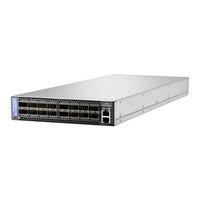
HPE SN2700M Hardware User Manual (124 pages)
StoreFabric M-Series Ethernet Switch Systems
Brand:
HPE
| Category:
Network Router
| Size: 7.79 MB
Table of Contents
Table of Contents
3
Table 1: Revision History Table
8
Chapter 1 Introduction to HPE Storefabric SN2000M Spectrum™ Based Ethernet Switch
9
Systems
9
Table 2: References
9
Overview
11
Speed and Switching
12
Table 3: Speed and Switching Capabilities
12
Figure 1: SN2700M Front Side View
12
Figure 2: Sn2410M/Sn2410Bm Front Side View
12
Figure 3: SN2100M Front Side View
12
Figure 4: SN2700M and Sn2410M/Sn2410Bm Rear Side View
12
Figure 5: SN2100M Rear Side View
12
Management Interfaces, Psus and Fans
13
Features
13
Certifications
13
Ordering Information
13
Table 4: Management Interfaces, Psus and Fans
13
Table 5: Ordering Part Numbers (Opns)
13
Chapter 2 Installation
15
Safety Warnings
15
System Installation and Initialization
15
Air Flow
16
Package Contents
16
Figure 6: Air Flow Direction Marking - Power Side Inlet to Connector Side Outlet
16
19" Systems Mounting Options
17
Static Rail Kit for SN2700M
17
Table 6: Installation Kit
17
Figure 7: Rack Rail Kit Parts
18
Figure 8: Installation Options
19
Figure 9: Attaching the Rails to the Chassis
19
Figure 10: Attaching the Brackets to the Chassis
20
Figure 11: Installing the Cage Nuts
20
Figure 12: Attaching the Brackets to the Rack
21
Figure 13: Sliding the Blades in the Rails
21
Telescopic Rail Kit for SN2700M
22
Table 7: Installation Kit
22
Figure 14: Rack Rail Kit Parts
23
Figure 15: Rails Separation
24
Figure 16: Installing the Cage Nuts
24
Figure 17: Mounting the Outer Rails into the Rack
25
Figure 18: Attaching the Inner Rails to the Chassis
25
Figure 19: Securing the Chassis in the Inner Rails
25
Figure 20: Sliding the Switch into the Rack
26
Figure 21: Pulling the Unit Outwards
27
Figure 22: Locking Mechanism
27
Static Rail Kit for Sn2410M/Sn2410Bm
28
Table 8: Installation Kit
28
Figure 23: Rack Rail Kit Parts
29
Figure 24: Installation Options
30
Figure 25: Attaching the Rails to the Chassis
30
Figure 26: Installing the Cage Nuts
31
Figure 27: Attaching the Rails to the Rack
31
Side by Side Mounting for SN2100M Rail Kit
32
Table 9: Installation Kit
32
Figure 28: Sliding the Blades in the Rails
32
Figure 29: Rack Rail Kit Parts
34
Figure 30: Coupling the Cables with Cable-Ties
35
Figure 31: Coupled Cables - Rear View
35
Figure 32: Cables Within the Rail
36
Figure 33: Attach the Blades to the System
36
Figure 34: Attached Rail with Threaded Cables - Top View
37
Figure 35: Sliding the Frame Sliders into the Rails
37
Figure 36: Installing the Cage Nuts
38
Figure 37: Attaching the Frame to the Rack
38
Figure 38: Sliding the System's Blades in the Rails
39
Cable Installation
40
Figure 39: SN2700M and SN2100M Cable Orientation
40
Figure 40: Sn2410M/Sn2410Bm Cable Orientation
40
Breakout Cables and Adapters
41
Figure 41: Breakout or Fanout Cables
41
Figure 42: SN2700M Splitting Options
42
Figure 43: Sn2410M/Sn2410Bm Splitting Options
42
Initial Power on
43
Figure 44: SN2100M Splitting Options
43
Figure 45: System Status Leds 5 Minutes after Power on in SN2700M
44
Figure 46: System Status Leds 5 Minutes after Power on in SN 2410
44
Figure 47: System Status Leds 5 Minutes after Power on in SN 2100
44
System Bring-Up
45
Configuring Network Attributes Using MLNX-OS
45
Figure 48: Two Power Inlets - Electric Caution Notifications
45
Table 10: Serial Terminal Program Configuration
46
Table 11: Configuration Wizard Session
46
Table 12: Configuration Wizard Session - Static IP Configuration
47
FRU Replacements
50
Power Supply
50
Fans
51
Figure 49: PS Unit Pulled out
51
Figure 50: Fan Module Latches
52
Chapter 3 Interfaces
54
Supported Interfaces
54
Data Interfaces
54
Table 13: High Power/Lr4 Transceivers Support
54
Figure 51: Using 4.5W Modules on Ports 49, 50, 55, 56 in Sn2410M/Sn2410Bm
54
Speed
55
RS232 (Console)
55
Management
55
Usb
55
Reset Button
56
Status and Port Leds
56
Leds
56
LED Notifications
56
Table 14: Leds Symbols
56
Figure 52: System Status Leds - Front and Rear Sides in SN2700M
57
Figure 53: System Status Leds - Front and Rear Sides in Sn2410M/Sn2410Bm
57
Table 15: System Status LED Assignments
58
Figure 54: System Status LED in SN2100M
58
Figure 55: Fan Status LED in SN2700M - Front and Rear Sides
58
Table 16: Fan Status Front LED Assignments
59
Table 17: Fan Status Rear LED Assignments (One LED Per Fan)
59
Figure 56: Fan Status LED in Sn2410M/Sn2410Bm - Front and Rear Sides
59
Figure 57: Fan Status LED in SN2100M
59
Figure 58: Power Status LED
60
Figure 59: SN2700M and Sn2410M/Sn2410Bm Rear Side Panel
60
Table 19: Power Supply Unit Status Front LED Assignments for SN2100M
61
Table 20: Power Supply Unit Status Rear LED Assignments
61
Table 21: Bad Port LED Assignments
62
Figure 60: SN2700M Port Leds
62
Figure 61: Sn2410M/Sn2410Bm SFP28 Port Leds
62
Figure 62: Sn2410M/Sn2410Bm QSFP28 Port Leds
62
Inventory Information
63
Table 22: Port Leds in Ethernet System Mode
63
Figure 63: SN2100M Port Leds
63
Figure 64: SN2700M Pull-Out Tab
64
Figure 65: Sn2410M/Sn2410Bm Inventory Information Illustration
64
Figure 66: SN2100M Pull-Out Tab
65
Chapter 4 Software Management
66
Upgrading Software
66
MLNX-OS Software Upgrade
66
Switch Firmware Update
66
Chapter 5 Troubleshooting
67
Troubleshooting Instructions
67
Table 23: Troubleshooting
67
Chapter 6 Specifications
69
SN2700M Series
69
Table 24: SN2700M Specifications
69
Sn2410M/Sn2410Bm Series
70
Table 25: Sn2410M/Sn2410Bm Specifications
70
SN2100M Series
71
Table 26: SN2100M Specifications
71
Table 27: Opns for Replacement Parts
72
Table 28: QSFP Interface Pins 1-23
74
Table 29: QSFP Interface Pins 24-38
75
Figure 67: Rear View of Module with Pin Placement
76
Figure 68: RJ45 to DB9 Harness Pinout
78
Installation Instructions
80
Weee Directive
83
Support and Other Resources
121
Regulatory Information
123
Warranty Information
123
Documentation Feedback
124
Advertisement
Related Products
HPE SN2410M
HPE SN2100M
HPE SN2410bM
HPE StoreFabric SN2000M Series
HPE StoreFabric SN2010M
HPE SN6500B
HPE SN6000B
HPE SN4500B
HPE SN3000B
HPE StoreFabric SN3600B
HPE Categories
Server
Switch
Network Router
Storage
Wireless Access Point
More HPE Manuals
Login
Sign In
OR
Sign in with Facebook
Sign in with Google
Upload manual
Upload from disk
Upload from URL