Table of Contents
Advertisement
HPE OfficeConnect 1920S
8G/24G/48G Switch Series
Management and Configuration
Guide
Abstract
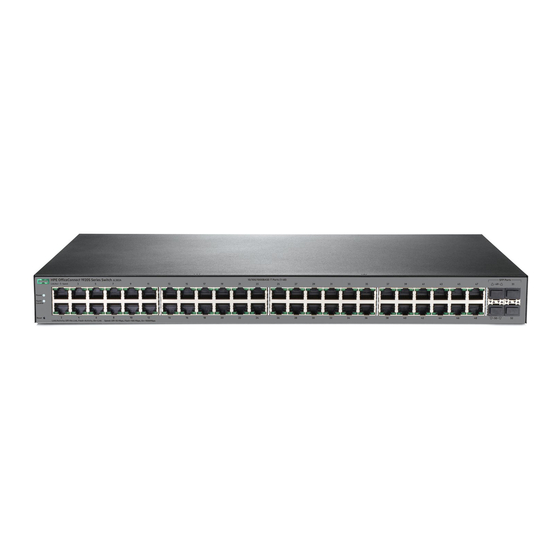
Use this guide to assist in managing the following HPE OfficeConnect 1920S switches:
HPE OfficeConnect 1920S 8G Switch (JL380A)
HPE OfficeConnect 1920S 24G Switch (JL381A)
HPE OfficeConnect 1920S 48G Switch (JL382A)
HPE OfficeConnect 1920S 8G PPoE+ (65W) Switch (JL383A)
HPE OfficeConnect 1920S 24G PPoE+(185W) Switch (JL384A)
HPE OfficeConnect 1920S 24G PoE+(370W) Switch (JL385A)
HPE OfficeConnect 1920S 48G PPoE+ (370W) Switch (JL386A)
Part Number: 5200-2836a
Published: June 2017
Edition: 2
Advertisement
Table of Contents


Need help?
Do you have a question about the OfficeConnect 1920S8G series and is the answer not in the manual?
Questions and answers