
Related Manuals for HPE SN2700M


Summary of Contents for HPE SN2700M
- Page 1 HPE StoreFabric M-Series SN2000M Spectrum™ Based Ethernet Switch Systems Hardware User Manual Models: SN2700M, SN2410M/SN2410bM and SN2100M Rev 1.0 Doc #: 882266-001 Published#: July 2017...
- Page 2 N o t i c e s © C o p y r ig h t 2 0 1 7 H e w le t t P a c k a r d E n t e r p r is e D e v e lo p m e n t L P T h e in f o r m a t io n c o n t a in e d h e r e in is s u b je c t t o c h a n g e w it h o u t n o t ic e.
-
Page 3: Table Of Contents
2.5.2 Telescopic Rail Kit for SN2700M ....... . . 22... - Page 4 6.1 SN2700M Series ........
- Page 5 Table 24: SN2700M Specifications ........
- Page 6 SN2100M Front Side View ..........12 Figure 4: SN2700M and SN2410M/SN2410bM Rear Side View ......12 Figure 5: SN2100M Rear Side View .
- Page 7 Figure 51: Using 4.5W Modules on Ports 49, 50, 55, 56 in SN2410M/SN2410bM ....54 Figure 52: System Status LEDs - Front and Rear Sides in SN2700M ......57 Figure 53: System Status LEDs - Front and Rear Sides in SN2410M/SN2410bM .
-
Page 8: Table 1: Revision History Table
Revision History Table 1 - Revision History Table Date Revision Description July 2017 Initial release of the first edition. User Manual... -
Page 9: Systems
About this Manual This manual describes the installation and basic use of the HPE StoreFabric M-Series SN2xxxM systems. Intended Audience This manual is intended for IT managers and system administrators. References Table 2 - References Document Description MLNX-OS® User Man- This document contains information regarding the configuration and man- agement of the MLNX-OS software. - Page 10 This icon indicates a situation that can potentially cause damage to hardware or software. This icon indicates a situation that can potentially cause personal injury. This icon indicates a situation that can potentially cause personal injury. User Manual...
-
Page 11: Overview
10, 25, 40, 50 and 100GbE in a large scale without changing power infrastruc- ture facilities. The Spectrum™ based 1U switch systems are a part of HPE StoreFabric M-Series’ complete end-to-end solution, which provides 10GbE through 100GbE interconnectivity within the data center. -
Page 12: Speed And Switching
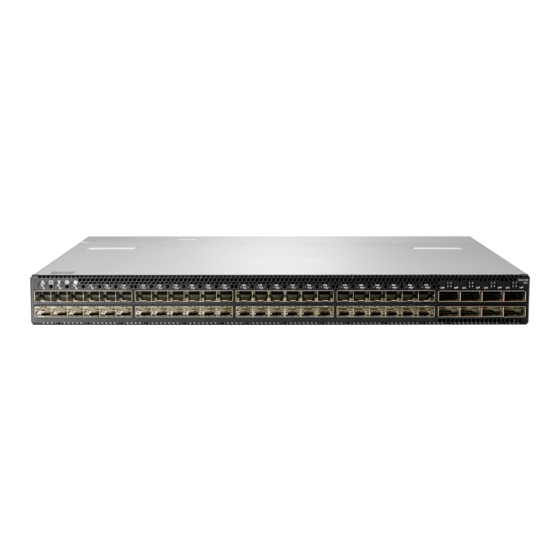
Figure 1: SN2700M Front Side View Figure 2: SN2410M/SN2410bM Front Side View Figure 3: SN2100M Front Side View Figure 4: SN2700M and SN2410M/SN2410bM Rear Side View Figure 5: SN2100M Rear Side View Speed and Switching Table 3 describes maximum throughput and interface speed per system model. -
Page 13: Management Interfaces, Psus And Fans
4 units (non- USB) replaceable) replaceable) Features For a full feature list, please refer to the system’s product brief in HPE’s website: https:// www.hpe.com. Certifications The list of certifications (such as EMC, Safety and others) per system for different regions of the world is located on the HPE website at: https://www.hpe.com... - Page 14 Table 5 - Ordering Part Numbers (OPNs) System HPE OPN Description Model SN2410M/ Q2F22-63001 HPE StoreFabric M-Series SN2410M 25GbE 48SFP28 8QSFP28 Switch SN2410bM Q6M27-63001 HPE StoreFabric M-Series SN2410M 25GbE 24SFP28 4QSFP28 Switch Q6M28-63001 HPE StoreFabric M-Series SN2410bM 10GbE 48SFP+ 8QSFP28 Switch Q6M29-63001...
-
Page 15: Chapter 2 Installation
Installation Installation Safety Warnings Prior to the installation, please review the safety warnings as follows: • For Nordic Countries Notices, see Section E.1, “Nordic Countries Notices,” on page • For Safety Warnings in English, see Section E.2, “Installation Safety Warnings (English),”... -
Page 16: Air Flow
The following information does not apply to SN2100M. In the SN2100M systems, the fan units are non-replaceable. All HPE StoreFabric M-Series switches have back-to-front air flow, as shown in Figure 6 All servers and systems in the same rack should be planned with the same airflow direction. -
Page 17: 19" Systems Mounting Options
A designated rail kit for the SN2100M systems can be purchased separately. If anything is damaged or missing, contact your HPE sales representative. 19” Systems Mounting Options By default, the SN2700M system is sold with the static rail kit described in Section 2.5.1. The... -
Page 18: Figure 7: Rack Rail Kit Parts
Figure 7: Rack Rail Kit Parts To mount the system into the rack: Before mounting the system to the rack, select the way you wish to place the system. Pay atten- tion to the airflow within the rack cooling, connector and cabling options. While planning how to place the system, consider the two installation options shown in Figure and review the following points:... -
Page 19: Figure 8: Installation Options
Installation Figure 8: Installation Options Attach the left and right rack mount rails (A) to the switch, by gently pushing the switch Step 1. chassis’ pins through the slider key holes, until locking occurs. Secure the chassis in the rails by screwing 2 flat head Phillips screws (E) in the designated Step 2. -
Page 20: Figure 10: Attaching The Brackets To The Chassis
Figure 10: Attaching the Brackets to the Chassis Install 8 cage nuts in the desired 1U slots of the rack: 4 cage nuts in the non-extractable side Step 4. (in the top and bottom holes only) and 4 cage nuts in the extractable side. Figure 11: Installing the Cage Nuts While each rack U (unit) consists of three holes, the cage nut should be installed verti- cally with its ears engaging the top and bottom holes only. -
Page 21: Figure 12: Attaching The Brackets To The Rack
Installation Figure 12: Attaching the Brackets to the Rack Slide the two blades into the left and right rails, and adjust them to fit your rack's depth. Use Step 6. four M6 screws (D) to fix the blades into the rack. Do not tighten the screws yet. Figure 13: Sliding the Blades in the Rails Secure the system in the rack by tightening the 8 screws inserted in Step 5 and Step 6 with a Step 7. -
Page 22: Telescopic Rail Kit For Sn2700M
Step 4. Remove the rails and brackets from the chassis by unscrewing 8 screws. Step 5. 2.5.2 Telescopic Rail Kit for SN2700M The Telescopic rail kit is not included in the system’s package, and can be purchased separately. There are two installation kit options: •... -
Page 23: Figure 14: Rack Rail Kit Parts
Installation Figure 14: Rack Rail Kit Parts User Manual... -
Page 24: Figure 15: Rails Separation
Figure 15: Rails Separation To separate the rails: 1. Extend the rail assembly by pulling the extension outwards (D). 2. Extract rail A from rail C by pushing it outside from the rear part of the assembly. To allow com- plete separation of rail A from rail C, press the quick-release latch. -
Page 25: Figure 17: Mounting The Outer Rails Into The Rack
Installation Figure 17: Mounting the Outer Rails into the Rack If cable accommodation is required, route the power cable and/or Eth cable through either Step 3. of the outer rails. Attach the switch to the left and right inner rails (A+B), by gently pushing the switch chas- Step 4. -
Page 26: Figure 20: Sliding The Switch Into The Rack
Figure 20: Sliding the Switch into the Rack When fully inserted, fix the switch by closing the remaining 2 screws in the middle and Step 7. tightening the 8 screws inserted in Step 2 with a torque of 4.5±0.5 Nm. 2.5.2.1 Removing the System from the Rack ... -
Page 27: Figure 21: Pulling The Unit Outwards
Installation Figure 21: Pulling the Unit Outwards Press on the locking spring (appears in red in Figure 22) on both sides simultaneously, and Step 4. continue pulling the unit towards you until it is fully removed. Figure 22: Locking Mechanism User Manual... -
Page 28: Static Rail Kit For Sn2410M/Sn2410Bm
2.5.3 Static Rail Kit for SN2410M/SN2410bM At least two people are required to safely mount the system in the rack. By default, the system is sold with the standard-depth rail kit. The short-depth rail kit can be supplied upon request. Table 8 - Installation Kit Kit OPN Rack Size and Rack Depth Range... -
Page 29: Figure 23: Rack Rail Kit Parts
Installation Figure 23: Rack Rail Kit Parts Before mounting the system to the rack, select the way you wish to place the system. Pay atten- tion to the airflow within the rack cooling, connector and cabling options. While planning how to place the system, consider the two installation options shown in Figure 24, and review the following points: •... -
Page 30: Figure 24: Installation Options
Figure 24: Installation Options Attach the left and right rack mount rails (A) to the switch, and secure the chassis in the rails Step 1. by screwing 2 flat head Phillips screws (D) in the designated points on each side (a total of 4 screws). -
Page 31: Figure 26: Installing The Cage Nuts
Installation three holes, the cage nut should be installed vertically with its ears engaging the top and bot- tom holes only. See Figure Figure 26: Installing the Cage Nuts While your installation partner is supporting the system’s weight, perform steps 3, 4 and 5: On the rear side of the cabinet, install the two blades (B) in the selected rack unit, using four Step 3. -
Page 32: Side By Side Mounting For Sn2100M Rail Kit
Figure 28: Sliding the Blades in the Rails Secure the system in the rack by tightening the 8 screws inserted in Step 3 and Step 4 with a Step 5. torque of 4.5±0.5 Nm. 2.5.4 Side by Side Mounting for SN2100M Rail Kit A designated rail kit for the SN2100M systems can be purchased separately. - Page 33 Installation • 2 system mounting blades with 8 screw holes - the kit contains enough rails to install 2 systems (B) • 2 system mounting blades with 7 screw holes - the kit contains enough rails to install 2 systems (C) •...
-
Page 34: Figure 29: Rack Rail Kit Parts
Figure 29: Rack Rail Kit Parts Before mounting the system to the rack, select the way you wish to place the system. Pay atten- tion to the airflow within the rack cooling, connector and cabling options. • The installation kits come with enough system mounted rails and flat head screws to install two systems. -
Page 35: Figure 30: Coupling The Cables With Cable-Ties
Installation Insert the SE (single ended) plugs to the dedicated inlets in the system’s rear panel. Step 1. Carefully position the SE (single ended) cables one on top of the other, and use three cable- Step 2. ties to pair them together, as shown in Figure While pairing the cables, make sure the cables are paired in symmetry to the switch, in order to avoid damaging the cables. -
Page 36: Figure 32: Cables Within The Rail
Figure 32: Cables within the Rail In the next you will be attaching the rails to the chassis, before doing that, make sure the cables are laid properly within them. Avoid using excessive pressure, as it can damage the cables. While holding the cables stably together in the blade’s rail with one hand, use your other Step 4. -
Page 37: Figure 34: Attached Rail With Threaded Cables - Top View
Installation Figure 34: Attached Rail with Threaded Cables - Top View Slide the two frame slides into the dedicated rails in the metal frame. See Figure Step 5. Figure 35: Sliding the Frame Sliders into the Rails Place the frame in the cabinet, and install ten cage nuts in the desired 1U slots of the rack: Step 6. -
Page 38: Figure 36: Installing The Cage Nuts
Figure 36: Installing the Cage Nuts Attach the frame to the rack by using ten spacer cage nut to adapt the square openings in the Step 7. vertical support, and screwing ten M6 pan head screws - four in the front part of the rack, and 6 in its rear part. -
Page 39: Figure 38: Sliding The System's Blades In The Rails
Installation Figure 38: Sliding the System’s Blades in the Rails User Manual... -
Page 40: Cable Installation
Greater insertion force may cause damage to the cable or to the cage. The SN2410M/SN2410bM system includes ports of different types. Figure 43 does not apply to the SFP28 ports. See Figure Figure 39: SN2700M and SN2100M Cable Orientation Figure 40: SN2410M/SN2410bM Cable Orientation User Manual... -
Page 41: Breakout Cables And Adapters
Splitting a 100GbE QSFP28 port to 4 separate 25GbE ports (using a breakout cable) disables (unmaps) the 100GbE port below it. See Figure 42,“SN2700M Splitting Options”. 2.6.1.1 Using Breakout Cables with MLNX-OS When using this feature, you should log into the MLNX-OS® CLI and configure the individual ports to be ‘split-2’... -
Page 42: Figure 42: Sn2700M Splitting Options
2.6.1.2 SN2700M Splitting Options Figure 42: SN2700M Splitting Options The top QSFP28 ports marked in green are splittable to 4 SFP28 ports, each. The bottom QSFP28 ports (gray) are blocked when the upper ports are in split mode. All QSFP28 ports marked in yellow can be split to 2 SFP28 ports. -
Page 43: Initial Power On
Step 3. It may take up to five minutes to turn on the system. If the System Status LED shows red after five minutes, unplug the system and call your HPE representative for assis- tance. Check the System Status LEDs and confirm that all of the LEDs show status lights consis- Step 4. -
Page 44: Figure 45: System Status Leds 5 Minutes After Power On In Sn2700M
Figure 45: System Status LEDs 5 Minutes After Power On in SN2700M Figure 46: System Status LEDs 5 Minutes After Power On in SN 2410 Figure 47: System Status LEDs 5 Minutes After Power On in SN 2100 User Manual... -
Page 45: System Bring-Up
If no obstacles were found and the problem persists, call your HPE representative for assistance. Figure 48: Two Power Inlets - Electric Caution Notifications... -
Page 46: Table 10: Serial Terminal Program Configuration
Configure a serial terminal program (for example, HyperTerminal, minicom, or Tera Term) Step 2. on your host PC with the settings described in Table 10. Once you perform that, you should get the CLI prompt of the system. Table 10 - Serial Terminal Program Configuration Setting Parameter Baud Rate... -
Page 47: Table 12: Configuration Wizard Session - Static Ip Configuration
Installation Table 11 - Configuration Wizard Session Wizard Session Display Comments You have entered the following The wizard displays a summary of your choices and then asks information: you to confirm the choices or to re-edit them. <A summary of the configura- Either press <Enter>... - Page 48 Check the software version embedded in your system, using the command ‘show version’. Step 6. Compare this version to the latest version that can be retrieved from HPE support site. To upgrade software, please refer to the MLNX-OS User Manual.
- Page 49 Installation 2.8.1.1.1 Disable Dynamic Host Configuration Protocol (DHCP) DHCP is used for automatic retrieval of management IP addresses. If a user connects through SSH, runs the wizard and turns off DHCP, the connection is immediately terminated, as the management interface loses its IP address. <localhost># ssh admin@<ip-address>...
-
Page 50: Fru Replacements
FRU Replacements The following information does not apply to the SN2100M series. The SN2100M systems include two non-replaceable power supply units and four non-replaceable fan units. 2.9.1 Power Supply The systems that are equipped with two replaceable power supply units work in a redundant con- figuration. -
Page 51: Fans
Installation Figure 49: PS Unit Pulled Out To insert a power supply unit: Make sure the mating connector of the new unit is free of any dirt and/or obstacles. Step 1. Do not attempt to insert a power supply unit with a power cord connected to it. Insert the power supply unit by sliding it into the opening, until a slight resistance is felt. -
Page 52: Figure 50: Fan Module Latches
To remove a fan unit: Grasping the handle with your right hand, push the latch release with your thumb while Step 1. pulling the handle outward. As the fan unit unseats, the fan unit status LEDs will turn off. Remove the fan unit. - Page 53 Installation User Manual...
-
Page 54: Chapter 3 Interfaces
(up to 3.5W) in all QSFP28 ports. Some QSFP28 ports support 4.5W trans- ceivers, as detailed in the following table: Table 13 - High Power/LR4 Transceivers Support Model Family Ports Maximum High Power Support SN2700M 1, 2, 31, 32 4.5W 49, 50, 55, 56 SN2410M/SN2410bM SN2100M 1, 2, 15, 16 a. -
Page 55: Speed
Interfaces 3.1.2 Speed Ethernet speed must be set manually. The system’s ports can be manually configured to run at speeds ranging from 10GbE to 100GbE (for more details, see “Specifications”). To change the port speed configuration, use the command “speed” under interface configuration mode. Refer to the MLNX-OS User Manual for instructions on port speed re-configuration. -
Page 56: Reset Button
3.1.6 Reset Button The reset button is located on the rear side of the system next to the fan status LEDs in SN2700M and SN2410M/SN2410bM, and on the front side in SN2100M. This reset button requires a tool to be pressed. -
Page 57: Figure 52: System Status Leds - Front And Rear Sides In Sn2700M
There are two PSU LEDs in SN2100M. 3.2.1.1 System Status LED Figure 52: System Status LEDs - Front and Rear Sides in SN2700M Both of these LEDs in the red ovals show the system’s status. Figure 53: System Status LEDs - Front and Rear Sides in SN2410M/SN2410bM Both of these LEDs in the red ovals show the system’s sta-... -
Page 58: Table 15: System Status Led Assignments
Both of the System Status LEDs (front and back, if exist) supply identical information. It may take up to five minutes to turn on the system. If the System Status LED shows red after five minutes, unplug the system and call your HPE representative for assis- tance. -
Page 59: Table 16: Fan Status Front Led Assignments
Interfaces Figure 56: Fan Status LED in SN2410M/SN2410bM - Front and Rear Sides Both of these LEDs in the red ovals show the fans’ status. Figure 57: Fan Status LED in SN2100M The SN2100M systems have a front fan LED only. Table 16 - Fan Status Front LED Assignments Description Action Required... -
Page 60: Figure 58: Power Status Led
Each power supply unit has a single 2 color LED on the right side of the unit, that indicates the status of the unit. Figure 59: SN2700M and SN2410M/SN2410bM Rear Side Panel User Manual... -
Page 61: Table 19: Power Supply Unit Status Front Led Assignments For Sn2100M
PSU might be faulty. PSU not present The power supply status LEDs on the rear side of the system (in SN2700M and SN2410M/ SN2410bM only) are located on the PSUs themselves. Each PSU has one LED of its own Table 20 does not apply to the SN2100M systems. -
Page 62: Table 21: Bad Port Led Assignments
Description Action Required No AC power to all power supplies. Call your HPE representative for assis- tance. 3.2.1.4 UID LED The UID LED is a feature that can be used to find a particular system within a cluster. The spe- cific system is signified by the blue UID LED. -
Page 63: Inventory Information
Interfaces Figure 63: SN2100M Port LEDs In the SN2410M/SN2410bM systems, the status of each pair of adjacent QSFP28 ports is indi- cated by four LEDs, as shown in the picture above: • While the bottom LEDs signify the port status in regular condition, the upper LEDs operate only when the port is split. -
Page 64: Figure 64: Sn2700M Pull-Out Tab
Figure 64: SN2700M Pull-out Tab Figure 65: SN2410M/SN2410bM Inventory Information Illustration User Manual... -
Page 65: Figure 66: Sn2100M Pull-Out Tab
Interfaces Figure 66: SN2100M Pull-out Tab User Manual... -
Page 66: Chapter 4 Software Management
Software and firmware updates are available from the HPE Support website. Check that your current revision is the latest one available on the HPE Support website. If you do not have the lat- est revision, upgrade your software using the CLI or the GUI. Copy the updated software to a known location on a remote server within the user’s LAN. -
Page 67: Chapter 5 Troubleshooting
Replace the FAN FRU if needed (possible in SN2700M and SN2410M/SN2410bM only) PSU Status LED is red Cause: Possible PSU issue Solution:. • Check/replace the power cable • Replace the PSU if needed (possible in SN2700M and SN2410M/SN2410bM only) User Manual... - Page 68 Table 23 - Troubleshooting Problem Indicator Symptoms Cause and Solution System boot failure Software upgrade failed Solution: while using on x86 based systems • Connect the RS232 connector (CONSOLE) to a MLNX-OS laptop. • Push the system’s reset button. • Press the ArrowUp or ArrowDown key during the system boot.
-
Page 69: Chapter 6 Specifications
Specifications Specifications SN2700M Series Table 24 - SN2700M Specifications Feature Value Mechanical Size: Standard - 1.72” (H) x 16.84” (W) x27” (D), 43.8mm (H) x 427.83mm (W) x 686.8mm (D) Mounting: 19” Rack mount Mounting: 19” Rack mount Weight: 1 PSU: 10.23kg, 2 PSUs: 11.1kg... -
Page 70: Sn2410M/Sn2410Bm Series
SN2410M/SN2410bM Series Table 25 - SN2410M/SN2410bM Specifications Feature Value Mechanical Size: 43.8mm (H) x 438mm (W) x 436mm (D) 1.72"(H) x 17.24"(W) x 17"(D) Mounting: 19" Rack mount Weight: 2 PSUs: 8.52kg Speed: 10/25GbE per port (ports 1-48), 10/25/40/50/56/100GbE per port (ports 49-56) Connector cage: 48xSFP28 and 8xQSFP28 Environmental Temperature:... -
Page 71: Sn2100M Series
Specifications SN2100M Series Table 26 - SN2100M Specifications Feature Value Mechanical Size: 43.8mm (H) x 200mm (W) x 508mm (D) 1.72" (H) x 7.87" (W) x 20" (D) Mounting: 19" Rack mount Weight: 4.540kg Speed: 10/25/40/50/56/100GbE per port Connector cage: 16xQSFP28 Environmental Temperature: Operational: 0°... -
Page 72: Table 27: Opns For Replacement Parts
Appendix A: Accessory and Replacement Parts Table 27 - OPNs for Replacement Parts Part Description MTEF-KIT-A Rack installation kit for 1U systems to be mounted into short or standard depth racks MTEF-KIT-S Rack installation kit for standard depth 1U systems to be mounted into stan- dard depth racks MTEF-KIT-BP Rack installation kit for 1U wide systems to be mounted into short depth... - Page 73 Appendix B: Thermal Threshold Definitions There are three thermal threshold definitions for the switch device which impact the overall switch system operation state: • Warning – 105°C: On managed systems only: When the device crosses the 100°C threshold, a Warning Threshold message will be issued by the management SW, indicat- ing to system administration that the switch has crossed the Warning threshold.
-
Page 74: Table 28: Qsfp Interface Pins 1-23
Appendix C: Interface Specifications SFP28 Interface Table 28 - QSFP Interface Pins 1-23 Connec Connect tor Pin or Pin Signal Description Numbe J3 and J6 Name J3 and J6 Ground Rx1n Rx2n Rx1n Rx2n Rx1p Tx2n Transmitter Inverted Data Input Rx2p Rx1p Rx2p... -
Page 75: Table 29: Qsfp Interface Pins 24-38
Table 29 - QSFP Interface Pins 24-38 Connector Connector Signal Description Pin Name Number Rx4n Receiver Inverted Data Output 3 Receiver Non-Inverted Data Output 3 Rx4p Ground Module Present ModPrsL IntL Interrupt Vcc Tx +3.3 V Power supply transmitter +3.3 V Power Supply Vcc 1 LPMode Low Power Mode... -
Page 76: Figure 67: Rear View Of Module With Pin Placement
SFP28 Interface 56.50 13.90 Mellanox Technologies 11.85 13.60 14.80 13.70 MTSFPP-SR Module 1.55 0.50 8.50 0.60 2.55 1.80 44.95 Figure 67: Rear View of Module With Pin Placement 13.70 8.50 User Manual... - Page 77 Symbol Name Description VeeT Transmitter Ground (Common with Receiver Ground) TX_Fault Transmitter Fault. TX_Disable Transmitter Disable. Laser output disabled on high or open. 2-wire Serial Interface Data Line 2-wire Serial Interface Clock Line MOD_ABS Module Absent. Grounded within the module No connection required RX_LOS Loss of Signal indication.
-
Page 78: Figure 68: Rj45 To Db9 Harness Pinout
RJ45 to DB9 Harness Pinout In order to connect a host PC to the Console RJ45 port of the system, a RS232 harness cable (DB9 to RJ45) is supplied. Figure 68: RJ45 to DB9 Harness Pinout User Manual... - Page 79 (EEE) should be collected separately and not disposed of with regular household waste. Dispose of this product and all of its parts in a responsible and environmentally friendly way. Follow the instructions found at https://www.hpe.com for proper disassembly and disposal of the switch, according to the WEEE directive. User Manual...
-
Page 80: Installation Instructions
Appendix E: Safety Warnings (Multiple Languages) Nordic Countries Notices In Finland: "Laite on liitettävä suojakoskettimilla varustettuun pistorasiaan" In Norway: "Apparatet må tilkoples jordet stikkontakt" In Sweden: "Apparaten skall anslutas till jordat uttag" Installation Safety Warnings (English) 1. Installation Instructions Read all installation instructions before connecting the equipment to the power source. 2. - Page 81 6. Stacking the Chassis The chassis should not be stacked on any other equipment. If the chassis falls, it can cause bodily injury and equipment damage. 7. Redundant Power Supply Connection - Electrical Hazard This product includes a redundant power or a blank in its place. In case of a blank power supply, do not operate the product with the blank cover removed or not securely fastened.
- Page 82 14. Equipment Disposal Disposal of this equipment should be in accordance to all national laws and regula- tions. 15. Local and National Electrical Codes This equipment should be installed in compliance with local and national electrical codes. 16. Installation Codes This device must be installed according to the latest version of the country national electrical codes.
-
Page 83: Weee Directive
21. Overcurrent Protection A readily accessible Listed branch circuit overcurrent protective device rated 20 A must be incorporated in the building wiring. 22. Do Not Use the Switch as a Shelf or Work Space Caution: Slide/rail mounted equipment is not to be used as a shelf or a work space. The rails are not intended for sliding the unit away from the rack. - Page 84 חבלת גוף כתוצאה מנשיאת משקל יתר .נדרשת נוכחותם של מספר מתקינים כדי להרים את המוצר בבטחה <40 lbs 70 - 121 lbs >121 lbs 40 - 70 lbs <18 kgs 32 - 55 kgs >55 kgs 18 - 32 kgs ציוד...
- Page 85 !בעת סופות ברקים - סכנת התחשמלות בעת סופות ברקים, אין להפעיל את המערכת או לחבר/לנתק כבלים חיבור או ניתוק של כבלי נחושת כבלי נחושת הם כבדים וקשיחים. לפיכך, יש לחברם ולנתקם מהמחברים בזהירות .רבה. לאזהרות נוספות, יש לעיין בעלון לצרכן מטעם יצרן הכבלים הרכבה...
- Page 86 תקנות התקנה יש להתקין מערכת זו על פי הגרסה האחרונה של תקנות החשמל המקומיות הנהוגות במדינה. עבור צפון אמריקה, יש להתקין את המערכת בהתאם לתקנות החשמל הלאומיות .המיושמות בארה”ב ובקנדה חיבור בין מערכות מסוג להיות בעלי הסמכת Ethernet -ו RS232 על...
- Page 87 安裝安全性警告 (Chinese) 1. 安裝指示 本設備附有備援電源供應器或在適當位置配有空白蓋板。 2. 因重量導致的人身受傷 為了安全起見,請安排足夠的人員以合力抬起本產品。 <40 lbs 70 - 121 lbs >121 lbs 40 - 70 lbs <18 kgs 32 - 55 kgs >55 kgs 18 - 32 kgs 3. 重設備 本設備極重,應使用機械式起重機來搬移,以避免人員受傷。 4. 有觸電的危險 有觸電的危險! 拆除風扇模組後,即可接觸到模組空腔內的電源針腳。 請勿將工具或機身零件插入到風扇模組空腔內。 5.
- Page 88 7. 複式電源連接時的電擊危險 本設備附有備援電源供應器或在適當位置配有空白蓋板。如果是電源供應器空 白蓋板,在空白蓋板已取下或未牢牢固訂的情況下,請勿操作本產品。 8. 雙極 / 中性保險絲 本系統具有雙極 / 中性保險絲。請拔掉所有電源線後,再打開本產品的蓋板或 碰觸任何內部零件。 9. 多電源輸入座 電擊與能源危害的危險。 所有 PSU 均各自獨立。 將所有電源供應器斷電,確保交換器平台內部在電源關閉狀態。 10. 閃電時的電擊危險 在閃電期間,不要使用本設備或連接或拔下纜線。 11. 機架安裝與維修 此產品已安裝在機架中或在機架中維修時,必須採取特定預防措施以確保系統 維持穩定。一般您應該將設備從底部到頂端放滿機架。 12. 設備安裝 本設備僅限由經過訓練與 / 或合格的人員安裝、更換或維修。 13. 設備棄置 棄置本設備應遵照所有國內法規。 14. 當地與國家電氣法規 請遵照當地與國家電氣法規安裝本設備。 User Manual...
- Page 89 15. 安裝法規 請務必遵循最新版的國家電氣法規,安裝本設備。在北美地區,請務必遵循美 國國家電工法規和加拿大電工法規中的適用規定,安裝本設備。 16. 更換電池 警告:只能以 UL 認可電池,且取得最大異常充電電流低於 4mA 認證的電池進 行更換。 若更換錯誤類型的電池,會有爆炸的危險。 請依據指示棄置廢電池。 17. UL 列名和 CSA 認證電源線 北美地區在接上電源時,請選用獲得 UL 列名和 CSA 認證、三個導體、[16 AWG] 附成型插頭,額定值為 125 V、[13 A],長度至少 1.5 公尺 [ 六英尺 ],但 不超過 4.5 公尺的電源線。 歐洲地區在接上電源時,請選用國際協調式且標示有 <HAR> 字樣、三個導體、 標稱截面至少...
- Page 90 22. WEEE 指令 根據 WEEE 指令 2002/96/EC,所有廢棄的電氣與電子設備 (EEE),應分開集 中,而且不應與一般家庭廢棄物一起棄置。 請以負責和環保的方式棄置本產品及其所有零件。 23. 挪威國家電源限制 本設備僅限連接至挪威的 TN 電源系統和 IT 電源系統。 User Manual...
- Page 91 24. China CCC Warning Statement 25. Taiwan BSMI Class A Statement - Warning to the User! User Manual...
- Page 92 Avertissements de sécurité pour l'installation (French) 1. Instructions d'installation Veuillez lire la totalité des instructions d'installation avant de relier l'équipement au secteur. 2. Blessures à cause du poids Prévoyez assez de personnel pour soulever ce produit en toute sécurité. <40 lbs 70 - 121 lbs >121 lbs 40 - 70 lbs...
- Page 93 8. Fusibles phase/neutre Ce système dispose de fusibles phase/neutre. Débranchez tous les cordons d'alimenta- tion avant d'ouvrir le capot ou de toucher tout élément à l'intérieur. 9. Plusieurs prises d'alimentation Risque et danger d'électrocution. Les alimentations sont toutes indépendantes. Pour s'assurer que le commutateur est bien hors tension, débranchez toutes les alimen- tations.
- Page 94 16. Codes d'installation Cet appareil doit être installé conformément à la version la plus récente des codes élec- trique nationaux. En Amérique du Nord, l'équipement doit être installé en respectant les exigences de l'US National Electrical Code et du Code canadien de l'électricité. 17.
- Page 95 23. Directive DEEE Selon la Directive 2002/96/CE (DEEE), tous les déchets d'équipements électriques et électroniques (EEE) doivent être collectés séparément et ne pas être mis au rebut avec les déchets ménagers habituels. Ce produit et toutes ses pièces doivent être mis au rebut d'une manière responsable, respectant l'environnement.
- Page 96 4. Stromschlagrisiko Stromschlagrisiko! Bei abgenommenem Ventilatormodul sind die Stromkontakte in der Modulvertiefung zugänglich. Es dürfen KEINE Werkzeuge oder Körperteile in die Vertiefung des Ventilatormoduls gelangen. 5. Übertemperatur Dieses Gerät sollte nicht in einem Bereich mit einer Umgebungstemperatur über der maximal empfohlenen Temperatur von 45°C (113°F) betrieben werden. Es ist ein Luft- strom von 200 LFM bei maximaler Umgebungstemperatur erforderlich.
- Page 97 11. Rack-Montage und Wartung Wenn dieses Produkt in einem Rack montiert oder gewartet wird, sind besondere Vor- sichtsmaßnahmen zu ergreifen, um die Stabilität des Systems zu gewährleisten. Im Allgemeinen sollten Sie das Gestell von unten nach oben mit Geräten füllen. 12.
- Page 98 18. Hoher Ableitstrom WARNUNG: Hohe Ableitstrom; Earth Verbindung, bevor Sie die Verbindung von wesentlicher Bedeutung werden. 19. Installationscodes Dieses Gerät muss installiert sein, entsprechend auf die neueste Version des Landes National Electrical Code. Für Nordamerika, müssen in Übereinstimmung mit den gel- tenden Vorschriften in der US-amerikanischen National Electrical Code und dem Canadian Electrical Code.
- Page 99 2. Lesión corporal a causa de peso Recurra a suficientes personas para levantar este producto sin <40 lbs 70 - 121 lbs >121 lbs 40 - 70 lbs <18 kgs 32 - 55 kgs >55 kgs 18 - 32 kgs 3.
- Page 100 8. Fusible neutro o de polo doble Dos fusibles, uno en el polo y otro en el neutro. Quitar los cables de corriente antes de abrir la tapa de este producto o tocar cualquier componente interno. 9. Tomas de alimentación múltiples Riesgo de descarga eléctrica y peligro de corriente.
- Page 101 16. Códigos de instalación Este dispositivo se debe instalar conforme a la versión más reciente de los códigos eléctricos nacionales del país en cuestión. En América del Norte, el equipo se debe instalar de acuerdo con las disposiciones vigentes del Código Eléctrico Nacional de los EE.UU.
- Page 102 22. No utilizar el conmutador como estante ni como espacio de trabajo Cuidado: Equipos montados en deslizadores o rieles no se deben utilizar como estantes ni como espacio de trabajo. La finalidad de los rieles no es deslizar la unidad hacia afuera del bastidor.
- Page 103 4. Опасность поражения электрическим током Опасность поражения электрическим током! Когда снят вентиляторный модуль, существует возможность повреждения контактов питания в его углублении. НЕ вставлять инструменты или части тела в углубление вентиляторного модуля. 5. Перегрев Не эксплуатировать это оборудование в помещении с температурой окружающей среды, превышающей...
- Page 104 11. Подсоединение и отсоединение медных кабелей Медные кабели тяжелые и негибкие, поэтому следует осторожно их подсоединять и отсоединять. За особыми предупреждениями и указаниями следует обратиться к производителю кабеля. 12. Установка или обслуживание в стойке При установке или обслуживании этого изделия в стойке следует обеспечить устойчивость...
- Page 105 18. Шнур питания, включенный в номенклатуру UL и сертифицированный Канадской ассоциацией стандартизации (CSA) Подключение к электропитанию в Северной Америке выполняется с помощью шнура питания, включенного в номенклатуру UL и сертифицированного Канадской ассоциацией стандартизации (CSA), 3-жильного, [16 AWG], длиной от 1,5 м [6 футов] до 4,5 м, с литой вилкой, рассчитанной на 125 В [13 А]. Подключение...
- Page 106 23. Директива WEEE В соответствии с Директивой 2002/96/EC (WEEE) отходы электрического и электронного оборудования должны собираться и утилизироваться отдельно от обычных бытовых отходов. Следует утилизировать это изделие и все его части ответственным и экологически безопасным способом. Avertismente privind siguranţa la instalare (Romanian) 1.
- Page 107 6. Suprapunerea cadrului Cadrul nu trebuie să fie suprapus peste niciun alt echipament. În cazul în care cadrul cade, poate cauza leziuni corporale şi deteriorări ale echipamentului. 7. Conexiunea la o sursă de alimentare electrică suplimentară - pericol electric Acest produs include o sursă de alimentare suplimentară sau un spaţiu gol în locul acesteia.
- Page 108 14. Eliminarea echipamentului Eliminarea acestui echipament trebuie să se realizeze în conformitate cu toate legile şi regulamentele naţionale. 15. Codurile electrice locale şi naţionale Acest echipament trebuie să fie instalat conform codurilor electrice locale şi naţionale. 16. Codurile ed instalare Acest dispozitiv trebuie să...
- Page 109 21. Interconectarea unităţilor Cablurile pentru conectarea la unitatea RS232 şi la interfeţele Ethernet trebuie să fie de tipul DP-1 sau DP-2 certificate UL. (Notă- când se regăsesc într-un circuit non-LPS) Protecţie la supracurent: Un dispozitiv de protecţie la supracurent, înregistrat în cir- cuitul de ramificare, uşor accesibil şi cu o putere nominală...
- Page 110 2. Tjelesne ozljede uslijed težine Kako biste sigurno podignuli ovaj proizvod, koristite dovoljan broj ljudi. <40 lbs 70 - 121 lbs >121 lbs 40 - 70 lbs <18 kgs 32 - 55 kgs >55 kgs 18 - 32 kgs Teška oprema Ova oprema je vrlo teška i treba se premještati pomoću mehaničkog dizala kako bi se izbjegle ozljede.
- Page 111 9. Višestruki ulazi za napajanje Rizik od strujnog udara i opasnost od električne energije. PSU jedinice su neovisne. Odspojite sva napajanja kako biste osigurali stanje bez napajanja unutar platforme preklopnika. 10. Tijekom udara munje - Opasnost od električne energije Tijekom djelovanja munja, nemojte raditi na opremi ili spajati ili odspajati kabele. 11.
- Page 112 17. Zamjena baterije Upozorenje: Bateriju zamijenite samo baterijom iz serije UL koja je certificirana za maksimalnu nepravilnu struju punjenja ne manju od 4 mA Postoji rizik od eksplozije ako se baterija zamijeni neodgovarajućom vrstom. Odložite prazne baterije sukladno uputama. 18. UL CSA kabel napajanja Za sjevernoameričku mrežu odaberite kabel napajanja koji je na UL listi i sa CSA cer- tifikatom, 3 - žilni, [16 AWG] (16 AWG) koji završava lijevanim utikačem nazivnog napona od 125 V, [13 A], minimalne duljine od 1,5 m [six feet] (šest stopa), ali ne dulji...
- Page 113 23. WEEE direktiva Sukladno WEEE direktivi 2002/96/EZ, sav električni i elektronički otpad (EEE) trebao bi se prikupljati zasebno i ne bi se trebao odlagati kao običan kućanski otpad. Odlaganje ovog proizvoda i svih njegovih dijelova vršite na odgovoran i ekološki način.
- Page 114 4. Rischio di scosse elettriche! Rischio di scosse elettriche! Con il modulo ventola rimosso, i pin di alimentazione sono accessibili all’interno della cavità del modulo. NON inserire strumenti o parti del corpo nella cavità del modulo della ventola. 5. Temperatura eccessiva Questa apparecchiatura non va utilizzata in un’area con una temperatura ambiente superiore a quella massima consigliata: 45 °C (113 °F).
- Page 115 12. Montaggio su rack e manutenzione Quando questo prodotto viene montato o sottoposto a manutenzione su un rack, è necessario adottare delle precauzioni speciali per assicurarsi che il sistema resti stabile. In generale, il rack va riempito con apparecchiature, procedendo dal basso verso l’alto. 13.
- Page 116 19. Corrente di dispersione elevata Avvertenza: corrente di dispersione elevata; il collegamento a terra è essenziale prima di collegare l’alimentazione. 20. Codici di installazionei Questo dispositivo va installato in conformità con l’ultima versione dei codici elettrici nazionali del Paese. Per il Nord America, l’apparecchiatura va installata in conformità con i requisiti applicabili del “codice elettrico nazionale USA”...
- Page 117 E.12 Montaj Güvenlik Uyarıları (Turkish) 1. Montaj Talimatları Ekipmanı güç kaynağına bağlamadan önce tüm montaj talimatlarını okuyun. 2. Ağırlık Nedeniyle Fiziksel Yaralanma Bu ürünü güvenli bir şekilde kaldırabilmek için yeterli sayıda insandan yardım alın. <40 lbs 70 - 121 lbs >121 lbs 40 - 70 lbs <18 kgs...
- Page 118 7. Yedekli Güç Kaynaðý Baðlantýsý -Elektrik Çarpma Tehlikesi Bu ürün, yedekli güç kaynağı veya onun yerine boş elektrik kutusu içerir. Güç kaynağı için boş elektrik kutusu varsa, kutunun kapağı açıkken veya tam olarak kapatılmamışken ürünü çalıştırmayın. 8. Çift Kutuplu/Nötr Kesmeli Sigorta Bu sistemde çift kutuplu/nötr kesmeli sigorta kullanılmaktadır.
- Page 119 15. Montaj Kodları Bu cihazın, ülke ulusal elektrik kodlarının son sürümüne göre monte edilmesi gerekir. Kuzey Amerika için, ekipmanın ABD Ulusal Elektrik Kodu ve Kanada Elektrik Kodu'nun uygulama koşullarına göre monte edilmesi gerekir. 16. Pilin Değiştirilmesi Uyarı: Yalnızca, maksimum düzgüsüz şarj akımı 4mA'dan az olmayan, UL Onaylı...
- Page 120 22. WEEE Yönergesi WEEE Yönergesi 2002/96/EC uyarınca, tüm elektrikli ve elektronik ekipman atıkları (EEE) ayrı olarak toplanmalı ve evsel atıklarla birlikte çöpe atılmamalıdır. Bu ürün ve tüm parçaları çevreye dost ve sorumlu bir şekilde imha edilmelidir. 23. Norveç Güç Kısıtlamaları Bu ünite, bir TN güç...
-
Page 121: Support And Other Resources
Support and other resources Accessing Hewlett Packard Enterprise Support • For live assistance, go to the Contact Hewlett Packard Enterprise Worldwide website: http://www.hpe.com/assistance • To access documentation and support services, go to the Hewlett Packard Enterprise Support Center website: http://www.hpe.com/support/hpesc Information to collect •... - Page 122 Important: Access to some updates might require product entitlement when accessed through the Hewlett Packard Enterprise Support Center. You must have an HPE Passport set up with relevant entitlements. Customer self repair Hewlett Packard Enterprise customer self repair (CSR) programs allow you to repair your prod- uct.
-
Page 123: Warranty Information
To view the warranty for your product or to view the Safety and Compliance Information for Server, Storage, Power, Networking, and Rack Products reference document, go to the Enterprise Safety and Compliance website: www.hpe.com/support/Safety-Compliance-EnterpriseProducts Additional warranty information HPE ProLiant and x86 Servers and Options www.hpe.com/support/ProLiantServers-Warranties HPE Enterprise Servers www.hpe.com/support/EnterpriseServers-Warranties HPE Storage Products www.hpe.com/support/Storage-Warranties... -
Page 124: Documentation Feedback
Hewlett Packard Enterprise is committed to providing documentation that meets your needs. To help us improve the documentation, send any errors, suggestions, or comments to Documentation Feedback (docsfeedback@hpe.com). When submitting your feedback, include the document title, part number, edition, and publication date located on the front cover of the document. For online help content, include the product name, product version, help edition, and publication date located on the legal notices page.
Need help?
Do you have a question about the SN2700M and is the answer not in the manual?
Questions and answers