Table of Contents
Advertisement
Quick Links
RC21012A/RC31012A
This document describes the following topics about
the RC21012A/RC31012A programmer board:
■
Basic hardware and GUI setup
■
Instructions to burn OTP memory of a device from
the GUI
Computer Requirements
■
USB 2.0 or USB 3.0 Interface
■
Processor: Minimum 1GHz
■
Memory:
●
Minimum: 512MB
●
Recommended: 1GB
■
Available disk space:
●
Minimum: 600MB (1.5GB 64-bit)
●
Recommended: 1GB (2GB 64-bit)
Board Contents
■
RC21012A/RC31012A programmer board
■
Programmer board manual
■
Configuration software (Renesas IC Toolbox)
■
Board schematic and BOM
R31UH0019EU0100 Rev.1.00
Aug 18, 2022
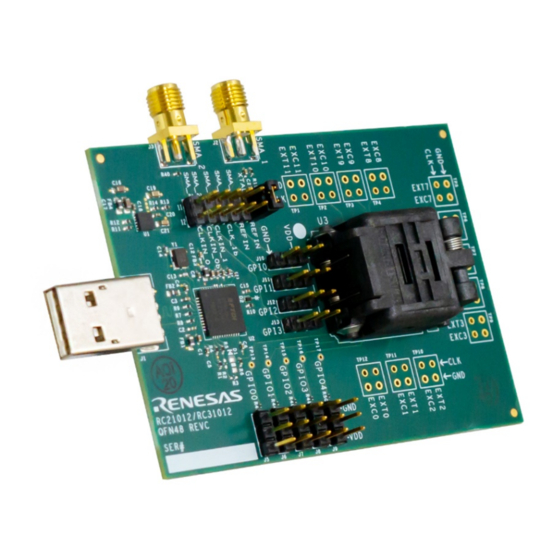
Figure 1. RC21012A/RC31012A Programmer Board
Programmer Board Manual
Features
■
USB power supply
■
Specialized device socket
■
Access to two differential input clocks
■
Test points for eight differential output clocks
■
XIN terminal can use laboratory signal generator
or OCXO/TCXO/XO components and board
■
Serial port for configuration and register read out
Page 1
© 2022 Renesas Electronics
Advertisement
Table of Contents

Related Manuals for Renesas RC21012A


Summary of Contents for Renesas RC21012A
-
Page 1: Figure 1. Rc21012A/Rc31012A Programmer Board
Recommended: 1GB (2GB 64-bit) Board Contents ■ RC21012A/RC31012A programmer board ■ Programmer board manual ■ Configuration software (Renesas IC Toolbox) ■ Board schematic and BOM Figure 1. RC21012A/RC31012A Programmer Board R31UH0019EU0100 Rev.1.00 Page 1 Aug 18, 2022 © 2022 Renesas Electronics... -
Page 2: Table Of Contents
Figure 11. DynamicMultiConfig Menu ........................8 Figure 12. Config Selection Options ......................... 8 Figure 13. Device Connection ..........................9 Figure 14. Program OTP ............................9 Figure 15. RC21012A/RC31012A Evaluation Board (Top) ..................10 Figure 16. RC21012A/RC31012A Evaluation Board (Bottom) ................10 R31UH0019EU0100 Rev.1.00 Page 2... -
Page 3: Functional Description
RC21012A/RC31012A EVK product page. Operational Characteristics The RC21012A/RC31012A programmer board is equipped with a single on-board LDO that takes voltage in from USB and supplies 3.3V to all device domains. The board is designed to plug directly into any PC and be ready for use with the RICBox GUI and blank part. -
Page 4: Part Placement
RC21012A/RC31012A Programmer Board Manual 1.2.1. Part Placement Part placement should follow the first pin marked on both the programmer board socket and blank part. Ensure both markings match before placing the part into the socket. Figure 3. Pin 1 Location Note: It is critical to ensure that pin 1 markings match between the board and device;... -
Page 5: Jumper Selection
1.2.2. Jumper Selection The RC21012A/RC31012A programmer board is equipped with five GPIO selection jumpers (J5-J9), four GPI selection jumpers (J10-J13), and a jumper strip for XIN/CLKIN trace paths (J4). The GPIO and GPI jumpers can be pulled high or low by placing a jumper shunt between the center pin and VDD, or GND accordingly. -
Page 6: Software Setup And Configuration
RC21012A/RC31012A programmer board. 1.3.2. Programming OTP Memory Programming OTP memory can be done easily inside the RICBox GUI. The RC21012A/RC31012A can program up to 27 configurations into OTP memory. To ensure that OTP memory is programmed correctly, complete the following procedure: 1. -
Page 7: Figure 9. Configuration Type Menu
RC21012A/RC31012A Programmer Board Manual 5. Use the Configuration Type drop-down menu to select between the following: ■ NoConfig – Nothing will be programmed to OTP memory. ■ SingleConfig – Program a single configuration into the OTP common configuration. ■ StaticMultiConfig – Program multiple configurations into a device that can be selectable at device start-up. -
Page 8: Figure 11. Dynamicmulticonfig Menu
RC21012A/RC31012A Programmer Board Manual 7. If DynamicMultiConfig is selected in the configuration type menu, the Dynamic User Config Selection section can now be used to set configuration selection bits. These have the same options as in StaticMultiConfig, except there are additional options to allow for differing types of input. -
Page 9: Figure 13. Device Connection
RC21012A/RC31012A Programmer Board Manual 9. Establish a connection to the device in socket. Figure 13. Device Connection 10. Press the “Program OTP” button on the OTP/EEPROM page. Figure 14. Program OTP R31UH0019EU0100 Rev.1.00 Page 9 Aug 18, 2022... -
Page 10: Board Design
RC21012A/RC31012A Programmer Board Manual 2. Board Design Figure 15. RC21012A/RC31012A Evaluation Board (Top) Figure 16. RC21012A/RC31012A Evaluation Board (Bottom) Schematic Diagrams The RC21012A/RC31012A schematic diagrams are located at the end of this document. R31UH0019EU0100 Rev.1.00 Page 10 Aug 18, 2022... -
Page 11: Bill Of Materials
RC21012A/RC31012A Programmer Board Manual Bill of Materials Table 2. Bill of Materials Qty. Reference Designator Description Manufacturer Part Number C1 C3 C10 X5R Surface Mount Capacitor Murata Electronics ZRB15XR61A475ME01 C2 C4 C5 C6 C7 C8 C11 C15 C18 X7R Surface Mount Capacitor... - Page 12 RC21012A/RC31012A Programmer Board Manual Qty. Reference Designator Description Manufacturer Part Number R4 R5 R7 R8 Surface Mount Resistor Panasonic ERJ-2GEJ100X Surface Mount Resistor Panasonic ERJ-2GEJ123X Surface Mount Resistor Vishay CRCW040227K0FK R15 R40 Surface Mount Resistor Panasonic ERJ-2RKF49R9X R16 R17 R18 R19 R20 R21 R22...
-
Page 13: Ordering Information
RC21012A/RC31012A Programmer Board Manual 3. Ordering Information Part Number Description RC21012_31012-PROG RC21012A/RC31012A Programmer Board 4. Revision History Revision Date Description 1.00 Aug 18, 2022 Initial release. R31UH0019EU0100 Rev.1.00 Page 13 Aug 18, 2022... - Page 16 Renesas' products are provided only subject to Renesas' Terms and Conditions of Sale or other applicable terms agreed to in writing. No use of any Renesas resources expands or otherwise alters any applicable warranties or warranty disclaimers for these products.
Need help?
Do you have a question about the RC21012A and is the answer not in the manual?
Questions and answers