Table of Contents
Advertisement
Quick Links
RC22308A/RC32308A
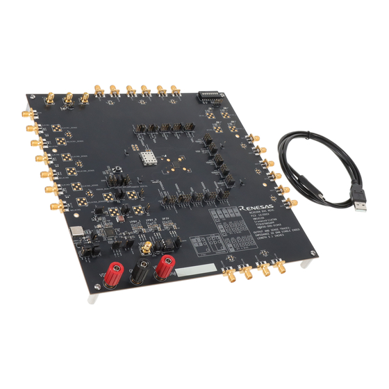
The RC22308A/RC32.308A Evaluation Board (EVB)
allows users to evaluate high-performance
synthesizer and jitter attenuator applications. This
document describes the following:
■
Basic hardware and GUI setup using Renesas IC
Toolbox (RICBox) software
■
Board power-up instructions
■
Instructions to get active output signals using a
provided configuration file
■
Hardware modifications required for different
conditions
Board Contents
■
RC22308A/RC32308A evaluation board
■
EVB manual
■
Configuration software (installable plugin for
RICBox)
■
Configuration example file for four built-in device
settings
■
Board schematic and BOM
R31UH0022EU0100 Rev.1.00
Jul 10, 2023
Features
■
Three differential clock inputs
■
Eight differential clock outputs
■
On-board EEPROM stores startup-configuration
data
■
XIN terminal can use laboratory signal generator
or OCXO/TCXO/XO components and board
■
Laboratory power supply connectors
■
USB-C power supply
■
Serial port for configuration and register read out
Computer Requirements
■
USB 2.0 or USB 3.0 interface
■
Processor: minimum 1GHz
■
Memory: minimum 512MB; recommended 1GB
■
Available disk space:
●
●
Figure 1. RC32308A Block Diagram
Evaluation Board Manual
Minimum: 600MB (1.5GB 64-bit)
Recommended: 1GB (2GB 64-bit)
© 2023 Renesas Electronics
Page 1
Advertisement
Table of Contents

Related Manuals for Renesas RC22308A


Summary of Contents for Renesas RC22308A
-
Page 1: Figure 1. Rc32308A Block Diagram
This ■ Eight differential clock outputs document describes the following: ■ On-board EEPROM stores startup-configuration ■ Basic hardware and GUI setup using Renesas IC data Toolbox (RICBox) software ■ XIN terminal can use laboratory signal generator ■ Board power-up instructions or OCXO/TCXO/XO components and board ■... -
Page 2: Table Of Contents
RC22308A/RC32308A Evaluation Board Manual Contents Functional Description ..........................4 Operational Characteristics ........................4 Hardware Setup and Configuration ....................... 4 1.2.1. Power and USB-C Connections to Computer Host ..............8 1.2.2. Overdrive the XIN with an External Signal ................10 1.2.3. - Page 3 Figure 27. Connect to the Device in RICBox ......................19 Figure 28. Connected Button ..........................19 Figure 29. Program Button ............................. 19 Figure 30. RC22308A/RC32308A Evaluation Board (Top) ..................20 Figure 31. RC22308A/RC32308A Evaluation Board (Bottom) ................21 R31UH0022EU0100 Rev.1.00...
-
Page 4: Functional Description
The device on the board accepts any input frequency from 1kHz to 1GHz. The RC22308A/RC32308A consists of a single APLL and DPLL design that allows for two separate frequency domains. The APLL can be used independently of the DPLL to generate synthesized clocks at the outputs that track the frequency of the input at the XIN pin. -
Page 5: Figure 2. Evaluation Board
RC22308A/RC32308A Evaluation Board Manual Figure 2. Evaluation Board See Table 1 and Figure 2 for the RC22308A/RC32308A evaluation board pin descriptions and functions. Table 1. RC22308A/RC32308A Evaluation Board Pin Descriptions On-Board Label No. Name Function Connector Label RC22308A/RC32308A Evaluation device 64-pin QFN. - Page 6 EEPROM socket 8-pin dip EEPROM socket. EEPROM WP Pull-up/down EEPROM write-protect pin.. FTDI I2C/SPI controller I2C/SPI control interface between PC and RC22308A/RC32308A I2C/SPI path connection J120 Combine or fanout SDI/SDO lines from the FTDI chip. Level translator enable J243 Enable/Disable I2C level translators.
- Page 7 RC22308A/RC32308A Evaluation Board Manual On-Board Label No. Name Function Connector Label I2C pull-up resistors J117, J118 Pull-up to FTDI 3.3V. LDO input voltage J124 Control LDO voltage source between USB and external 5V supply. selection jumper For proper functionality out of the box, the jumpers on board should be placed to allow the correct voltages at each LDO and domain.
-
Page 8: Power And Usb-C Connections To Computer Host
1.2.1. Power and USB-C Connections to Computer Host The EVB is connected to a computer host via the USB3.0 to USB-C cable. It is recommended that the cable be connected to a USB3.0 port; however, a USB2.0 port acceptable due to the RC22308A/RC32308A for I C/SPI communications only. -
Page 9: Figure 3. Usb Power Jumpers
RC22308A/RC32308A Evaluation Board Manual Figure 3. USB Power Jumpers 1.2.1.2. Power the Device with External Power Supply Connection and On-board Voltage Regulators ■ Set jumper on J124 between pins 2 and 3 ■ Set jumper on J259 between pins 2 and 3 ■... -
Page 10: Overdrive The Xin With An External Signal
3.3V. Supplying 3.3V to any other domain may cause damage to the RC22308A/RC32308A device. 1.2.2. Overdrive the XIN with an External Signal The RC22308A/RC32308A device can support between 25MHz and 80MHz on the XIN (crystal oscillator input) pin. There are three options for providing an input signal to the device XIN pin: ■... -
Page 11: On-Board Crystal Mount
RC22308A/RC32308A Evaluation Board Manual 1.2.3. On-board Crystal Mount The crystal mounting position can only be used if there is no other signal present on the XIN path (see Figure 9). In order to set up the evaluation board for crystal input: 1. -
Page 12: On-Board Xo Mount
RC22308A/RC32308A Evaluation Board Manual 1.2.4. On-board XO Mount For an XO to work properly at U27, the following must be set up: 1. Populate C229 with 0 Ohms, or 0.1µF if ac-coupling. 2. Depopulate U3, C1, C2, R6, R423, and R424. -
Page 13: Clock Inputs
RC22308A/RC32308A Evaluation Board Manual 1.2.5. Clock Inputs The RC32308A can accept two differential clock inputs to be used as a jitter attenuator source. To enable proper connection, make sure the input termination resistor setup corresponds to the input signal that is connected. The evaluation board allows for terminations across to a GND source at each input connection. -
Page 14: Serial Connection
RC22308A/RC32308A Evaluation Board Manual Place 50Ω across each leg, for a total 100Ω across, to terminate for LVDS. Figure 14. LVDS Input Clock Termination Place 50Ω to GND at each leg for HCSL terminations. Figure 15. HCSL Input Clock Termination 1.2.7. -
Page 15: On-Board Eeprom
RC22308A/RC32308A Evaluation Board Manual 1.2.8. On-board EEPROM The EVB also supports an external EEPROM IC for loading of an RC22308A/RC32308A configuration programmed into the EEPROM as an option. To load the configurations from EEPROM, the EEPROM load enable bit must be set in device OTP. If the enable bit is not set, the EEPROM load will be skipped. -
Page 16: Gpio Dip Switch Selectors
1.2.9. GPIO DIP Switch Selectors The EVB has one DIP switch set (SW1) to support GPIO pins on the RC22308A/RC32308A device. GPIOs 0-3 can support a two-level input (low/high). The middle position of the DIP switches leaves the pin open so the GPIOs can be controlled with internal pull-up and pull-down resistors. -
Page 17: Software Setup And Configuration
1 and 11. 1.3.2. Launch the GUI ® After successfully installing the Renesas IC Toolbox software, launch the software from the Windows <Start> menu at the bottom-left corner of the screen. 1. Click Start > RICBox to open the initial RICBox window. -
Page 18: Figure 25. Ricbox Wizard Navigation
RC22308A/RC32308A Evaluation Board Manual 5. Follow the on-screen wizard (see Figure 25) to configure the device for general evaluation starting from “Inputs”, then “DPLL”, and finally ”Outputs”. Figure 25. RICBox Wizard Navigation 6. Click on the Finish button after the settings are decided and to review the control panel page. -
Page 19: Configure The Evaluation Board
RC22308A/RC32308A Evaluation Board Manual 1.3.3. Configure the Evaluation Board 1. To establish communication between the EVB and the GUI, click the Not Connected button in the lower right corner, then click Connect. Figure 27. Connect to the Device in RICBox 2. -
Page 20: Board Design
RC22308A/RC32308A Evaluation Board Manual 2. Board Design Figure 30. RC22308A/RC32308A Evaluation Board (Top) R31UH0022EU0100 Rev.1.00 Page 20 Jul 10, 2023... -
Page 21: Figure 31. Rc22308A/Rc32308A Evaluation Board (Bottom)
RC22308A/RC32308A Evaluation Board Manual Figure 31. RC22308A/RC32308A Evaluation Board (Bottom) R31UH0022EU0100 Rev.1.00 Page 21 Jul 10, 2023... -
Page 22: Bill Of Materials (Bom)
RC22308A/RC32308A Evaluation Board Manual Bill of Materials (BOM) Item Reference Part Mfr. Part # C1,C30,C71,C72,C96,C97,C117,C119 0.1uF C0603C104K5R C13,C18,C19,C24,C27,C33,C67,C69,C92,C94,C110,C1 16,C189,C190,C193,C194,C198,C200,C202,C204,C206, 0.1uF GCM155R71E104KE02D C207,C208,C209,C210,C218,C219,C220,C221,C228,C2 C38,C41,C46,C49,C50,C53,C54,C57,C58,C61,C62,C65, C75,C78,C79,C82,C83,C86,C100,C103,C104,C107,C12 0.1uF GRM21BR71E104K 9,C132,C145,C148,C149,C152,C195,C222,C225 C39,C40,C47,C48,C51,C52,C55,C56,C59,C60,C63,C64, C76,C77,C80,C81,C84,C85,C101,C102,C105,C106,C13 10uF GRM21BC71E106K 0,C131,C146,C147,C150,C151,C196,C223,C224,C232 C66,C68,C91,C93,C109,C115 10uF GRM188D70J106MA73D C70,C73,C95,C98,C111,C118 22uF GRM188R60J226M C74,C99,C124 GCM188R71E105KA64D... - Page 23 RC22308A/RC32308A Evaluation Board Manual Item Reference Part Mfr. Part # J112,J113,J114,J115,J121 Headerstrip 1X1 68000-401HLF J125 Banana Black 571-0100 R2,R99,R100,R141,R149,R152,R155 4.70K CRCW06034K70FK R3,R144,R150,R153,R156,R200 1.50K CRCW06031K50FK 50.0 CRCW060350R0FK R50,R59,R380,R381,R382,R383,R405,R406,R435,R436 0.00 ERJ-2GE0R00X R126,R127,R129,R131,R409,R410 1.00K CRCW06031K00FKTA R171,R178,R186,R211,R212,R213,R214 10.0K RC0402JR-0710KL R176,R183,R191 0.00 CRCW06030000Z0 R196,R197 4.70K...
-
Page 24: Ordering Information
RC22308A/RC32308A Evaluation Board Manual 3. Ordering Information Part Number Description RC32308A-EVK RC22308A/RC32308A Evaluation Board 4. Revision History Revision Date Description 1.00 Jul 10, 2023 Initial release. R31UH0022EU0100 Rev.1.00 Page 24 Jul 10, 2023... - Page 25 Renesas' products are provided only subject to Renesas' Terms and Conditions of Sale or other applicable terms agreed to in writing. No use of any Renesas resources expands or otherwise alters any applicable warranties or warranty disclaimers for these products.
Need help?
Do you have a question about the RC22308A and is the answer not in the manual?
Questions and answers