Table of Contents
Advertisement
Quick Links
Advertisement
Table of Contents

Related Manuals for ADTRAN T1 ESF CSU ACE


Summary of Contents for ADTRAN T1 ESF CSU ACE
- Page 1 T1 ESF CSU ACE User Manual Part Number 1203025L1 61203025L1-1C May 2001...
- Page 2 Trademark Information: T-WATCH is a trademark of ADTRAN. OpenView is a registered trademark of Hewlett Packard Company. SunNet Manager is a trademark of Sun Micro Systems, Inc. 901 Explorer Boulevard P.O. Box 140000 Huntsville, AL 35814-4000 (256) 963-8000 © 2001 ADTRAN, Inc.
- Page 3 The following conventions are used in this manual. Notes provide additional useful information. Cautions signify information that could prevent service interruption. Warnings provide information that could prevent damage to the equip- ment or endangerment to human life. Important Safety Instructions When using your telephone equipment, please follow these basic safety precautions to reduce the risk of fire, electrical shock, or personal injury: Do not use this product near water, such as near a bathtub, wash bowl, kitchen...
- Page 4 Affidavit Requirements for Connection to Digital Services • An affidavit is required to be given to the telephone company whenever digital terminal equipment without encoded analog content and billing protection is used to transmit digital signals containing encoded analog content which are intended for eventual conversion into voice band analog signal and transmitted on the network.
- Page 5 Affidavit for Connection of Customer Premises Equipment to 1.544 MBPS and/ or Subrate Digital Services For the work to be performed in the certified territory of ______________ (telco name) State of ________________________________ County of ______________________________ I, _______________________ (name), ____________________ (business address), _____________________ (telephone number) being duly sworn, state: I have the responsibility for the operation and maintenance of the terminal equipment to be connected to 1.544 Mbps and/or __________________ subrate digital services.
- Page 6 ( ) D. In lieu of the proceeding training requirements, the operator(s)/maintainer(S) is (are) under the control of a supervisor trained in accordance with _______________ (circle one) above. I agree to provide ____________________ (telco’s name) with proper documentation to demonstrate compliance with the information in the preceding paragraph, if so requested.
- Page 7 If experiencing difficulty with this equipment, please contact ADTRAN for repair and warranty information. If the equipment is causing harm to the network, the tele- phone company may request this equipment to be disconnected from the network until the problem is resolved or it is certain that the equipment is not malfunctioning.
- Page 8 Federal Communications Commission Radio Frequency Interference Statement This equipment has been tested and found to comply with the limits for a Class A dig- ital device, pursuant to Part 15 of the FCC Rules. These limits are designed to provide reasonable protection against harmful interference when the equipment is operated in a commercial environment.
- Page 9 Canadian Equipment Limitations Notice: The Canadian Industry and Science Canada label identifies certified equip- ment. This certification means that the equipment meets certain telecommunications network protective, operational, and safety requirements. The Department does not guarantee the equipment will operate to the user’s satisfaction. Before installing this equipment, users should ensure that it is permissible to be con- nected to the facilities of the local telecommunications company.
- Page 10 (including, but not limited to, loss of data or information, loss of profits, or loss of use). ADTRAN is not liable for damages for any cause whatso- ever (whether based in contract, tort, or otherwise) in excess of the amount paid for the item.
- Page 11 Customer Service, Product Support Information, and Training ADTRAN will replace or repair this product within five years from the date of ship- ment if the product does not meet its published specification, or if it fails while in ser- vice.
- Page 12 The Enterprise Network (EN) Technical Training Department offers training on our most popular products. These courses include overviews on product features and func- tions while covering applications of ADTRAN's product lines. ADTRAN provides a va- riety of training options, including customized training and courses taught at our facilities or at your site.
-
Page 13: Table Of Contents
List of Figures ........................xvii List of Tables ........................xix Chapter 1. Introduction T1/FT1 Overview ........................ 1-1 T1 Service Offerings...................... 1-1 T1 ESF CSU ACE Overview ....................1-2 Features .......................... 1-5 Interface Features ....................1-6 NI (Labeled NET) ..................1-6 T1 (Labeled CPE) ................... 1-6 Control Port Input (Labeled EIA-232) ............ - Page 14 T1 HISTORY ....................3-9 CONFIG ........................3-9 NETWORK (NI) ..................... 3-9 UNIT ........................ 3-9 TERMINAL (T1) ..................... 3-9 UTIL ........................3-9 TIME/DATE ....................3-9 SOFTWARE REV ..................3-10 REINIT UNIT ....................3-10 ADDRESS ...................... 3-10 T1 ESF CSU ACE User Manual 61203025L1-1...
- Page 15 3)TEST PATTERN, Submenu of 4)TEST ..........3-26 4)RUN SELFTEST, Submenu of 4)TEST ........... 3-26 Appendix A. Pinouts ....................... A-1 Appendix B. Specification Summary ................B-1 Appendix C. Acronyms/Abbreviations................ C-1 Appendix D. Glossary ..................... D-1 Index ...........................Index-1 61203025L1-1 T1 ESF CSU ACE User Manual...
- Page 16 Table of Contents T1 ESF CSU ACE User Manual 61203025L1-1...
-
Page 17: List Of Figures
Figure 1-8. Channel Bank Application ................1-12 Figure 2-1. Power Connection ..................2-2 Figure 3-1. T1 ESF CSU ACE Front Panel Layout ............3-2 Figure 3-2. Selecting a Menu Item from the Main Menu..........3-3 Figure 3-3. Menu with Additional Item(s) Not Shown..........3-4 Figure 3-4. - Page 18 Figure 3-19. Re-initialize Unit/Address Screen ............. 3-23 Figure 3-20. Test Menu Tree....................3-24 Figure 3-21. Local Loopback Test Screen................. 3-25 Figure 3-22. Self Test Result Screen .................. 3-27 Figure A-1. Power Connection Wiring ................A-1 xviii T1 ESF CSU ACE User Manual 61203025L1-1...
-
Page 19: List Of Tables
List of Tables Table A-1. RJ-48C Connector Pin Assignments............A-2 Table A-2. EIA-232 Connector Pin Assignments ............A-2 61203025L1-1 T1 ESF CSU ACE User Manual... - Page 20 List of Tables T1 ESF CSU ACE User Manual 61203025L1-1...
-
Page 21: Chapter 1. Introduction
(ESF), is available. ESF provides a non-disruptive means of full- time monitoring on the digital facility. It was originally used by service providers to monitor the performance of their service 61203025L1-1 T1 ESF CSU ACE User Manual... -
Page 22: T1 Esf Csu Ace Overview
Most carriers (regional or local telcos), when supplying a T1 line to customer premises equipment (CPE), require an interface to monitor the T1 line. The T1 ESF CSU ACE (extended superframe channel service unit advanced communication equipment) provides the required interface between the CPE (such as DSUs, channel banks, T1 multiplexers, and PBXs) and telco or private T1 facilities. - Page 23 The unit provides the simultaneous use of performance report messages of ANSI T1.403 and maintenance messages of AT&T TR54016. The T1 ESF CSU ACE also provides conversion from SF to ESF framing formats, allowing older SF data terminal equipment (DTE) to take advantage of superior diagnostic capabilities of ESF T1 facilities.
-
Page 24: Figure 1-2. T1 Esf Csu Ace Front View
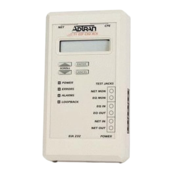
Chapter 1. Introduction Figure 1-2 shows the T1 ESF CSU ACE, and Figure 1-3 shows the jack signal directions. Figure 1-2. T1 ESF CSU ACE Front View T1 ESF CSU ACE User Manual 61203025L1-1... -
Page 25: Features
Chapter 1. Introduction Figure 1-3. Jack Signal Directions Features The following features give the T1 ESF CSU ACE many advantages over other products of its kind: • Smallest T1 ESF CSU ACE in the industry. • Front panel interface eliminates the need for a terminal to configure the T1 ESF CSU ACE. -
Page 26: Interface Features
EIA-232 input from a PC or a modem for control of the T1 ESF CSU ACE • Up to 9600 baud operation • Acts as input for PC or proxy agent control • VT-100 terminal interface T1 ESF CSU ACE User Manual 61203025L1-1... -
Page 27: Four Methods Of Control
SNMP Proxy Agent (1950007L1) to a network management system such as OpenView® or SunNet Manager™. The proxy agent runs on a PC and can interface to the T1 ESF CSU ACE directly or through a modem, in the same manner as the T-Watch PC programs. -
Page 28: Ascii Terminal
The ADTRAN T1 ESF CSU ACE recognizes an escape sequence that puts the unit into the ASCII terminal mode. After receiving the sequence, the T1 ESF CSU ACE sends front panel information to the terminal. This interface acts exactly like the front panel, but the advantage is that it can be accessed remotely (through a modem). -
Page 29: Loopback Tests
• Payload Loopback - Similar to line loopback, except that the framing is extracted from the received data and then regenerated for the transmitted data. Figure 1-4. Network Loopback Tests 61203025L1-1 T1 ESF CSU ACE User Manual... -
Page 30: Dte Interface Loopbacks
Figure 1-5. DTE Interface Loopback Pattern Generation The T1 ESF CSU ACE offers three test patterns: All Ones, All Zeros, and 1:8. These patterns can be initiated from the front panel, through the EIA-232 control port, or remotely via a management software like T-Watch. -
Page 31: Applications
Three applications are shown in this section. Figure 1-6 shows a general data application; Figure 1-7 on page 1-12 shows a general voice application; and Figure 1-8 on page 1-12 shows a channel bank application. Figure 1-6. General Data Application 61203025L1-1 T1 ESF CSU ACE User Manual 1-11... -
Page 32: Figure 1-7. General Voice Application
Chapter 1. Introduction Figure 1-7. General Voice Application DSX-1 DSX-1 Figure 1-8. Channel Bank Application 1-12 T1 ESF CSU ACE User Manual 61203025L1-1... -
Page 33: Chapter 2. Installation
If damage is suspected, file a claim immediately with the carrier and then contact ADTRAN Technical Support. If possible, keep the original shipping container to ship the T1 ESF CSU ACE back for repair or to verify damage during shipment. -
Page 34: Power Connection
A-1 on page A-1 for power connection wiring. Figure 2-1. Power Connection With the T1 ESF CSU ACE face up, plug the cable in with the plug ori- ented as shown in Figure 2-1. T1 ESF CSU ACE User Manual... -
Page 35: Wiring
See Table A-1 on page A-2 for the RJ-48 connector pin assignments. EIA-232 Connector The EIA-232 connector is used to connect the T1 ESF CSU ACE to a proxy agent, T-Watch, an ASCII terminal, or a modem. See Table A-2 on page A-2 for the connector pin assignments. -
Page 36: Power-Up Testing And Initialization
Chapter 2. Installation POWER-UP TESTING AND INITIALIZATION When shipped from the factory, the T1 ESF CSU ACE is set to factory default conditions; it is not initialized. At the first application of power, the unit automatically executes self test followed by an initialization sequence that sets up the unit. -
Page 37: Chapter 3. Operation
Operation Chapter 3 The T1 ESF CSU ACE can be configured and controlled via the local front panel, the EIA-232 control port, or T-Watch. This chapter describes configuration from the front panel. 61203025L1-1 T1 ESF CSU ACE User Manual... -
Page 38: Front Panel Operation
Chapter 3. Operation FRONT PANEL OPERATION The T1 ESF CSU ACE front panel operating functions are shown in Figure 3-1 and defined in this section. Figure 3-1. T1 ESF CSU ACE Front Panel Layout T1 ESF CSU ACE User Manual... -
Page 39: General Menu Operation
Chapter 3. Operation GENERAL MENU OPERATION The T1 ESF CSU ACE uses a multilevel menu structure containing both menu items and data fields. All menu operations and data are displayed in the LCD window. The menu items are numbered and can be viewed by using the up and down keys. -
Page 40: Selecting A Submenu Item
See Figure 3-4. Figure 3-4. Submenu Indicating Additional Items Not Shown T1 ESF CSU ACE User Manual 61203025L1-1... -
Page 41: Setting/Cancelling The Data Field
Cancelling is available any time during the operation. If Cancel is used prior to pressing Enter after making a data change, the original data val- ue is restored and the cursor returns to the submenu field. 61203025L1-1 T1 ESF CSU ACE User Manual... -
Page 42: View Display Only Data Fields
Press the Cancel key to exit a menu field or return to a previous menu level. MENU STRUCTURE The T1 ESF CSU ACE uses hierarchical menus to access its many features. The top-most, or Main menu level (see Figure 3-6 and Figure 3-8) leads to submenus which are grouped by functionality. -
Page 43: Figure 3-7. T1 Esf Csu Ace Menutree
3)TEST PATTERN ALL ZEROS 1:8 ALL DS0s ALL ONES 4)RUN SELFTEST *T1 ERR/ALM has same menu sub-branches as NI ERR/ALM. **T1 HISTORY has same as NI HISTORY. Figure 3-7. T1 ESF CSU ACE MenuTree 61203025L1-1 T1 ESF CSU ACE User Manual... -
Page 44: Figure 3-8. Four Opening Menus And First Level Submenus
TEST. Each Main menu item has several functions and submenus to identify and access specific parameters. In the discussions that follow, each Main menu item contains a complete menu diagram to identify the location of each operation. T1 ESF CSU ACE User Manual 61203025L1-1... -
Page 45: The Four Opening Menu Functions
Use to set all of the parameters associated with the network interface. UNIT Use to control T1 ESF CSU ACE control port baud rate and to set up the dial out function. TERMINAL (T1) Use to set all parameters associated with the terminal interface. -
Page 46: Util
Test results are displayed in the LCD window. The execution of tests disrupts some normal operations. See individual menu items concerning test before executing. LOCAL LOOPBACK Use to select loopbacks internal to the T1 ESF CSU ACE. 3-10 T1 ESF CSU ACE User Manual 61203025L1-1... -
Page 47: Rem Lb
Chapter 3. Operation REM LB Use to send remote loopback codes to the far end T1 ESF CSU ACE. TEST PATTERN Use to select a test pattern to send out the network interface of the T1 ESF CSU ACE. RUN SELFTEST Use to initiate a self test. -
Page 48: Detailed Menu Operation
FRAME BIT ERRORS 4)T1 ERR ALM* 5)T1 HISTORY** *T1 ERR/ALM has the same menu sub-branches as NI ERR/ALM. **T1 HISTORY has the same sub-branches as NI HISTORY. Figure 3-9. Status Menu Tree 3-12 T1 ESF CSU ACE User Manual 61203025L1-1... -
Page 49: Ni Perf Rpts, Submenu Of 1)Status
1)NI PERF RPTS, Submenu of 1)STATUS The Network Interface Performance Reports menu item displays the user copy of the performance data. The T1 ESF CSU ACE maintains this performance data on the network in compliance with ANSI T1.403 andAT&T document TR54016. The data displayed is data accumulated over the last 15 minutes and over the last 24 hours. -
Page 50: Ni Err/Alm, Submenu Of 1)Status
Unframed all-ones received at NI Out of Frame No framing pattern sync at NI Yellow Alarm Receiving yellow alarm pattern from NI LOS (loss of signal)/out of frame (OOF) Red Alarm causing red alarm at NI 3-14 T1 ESF CSU ACE User Manual 61203025L1-1... -
Page 51: Ni History, Submenu Of 1)Status
5)TI HISTORY, Submenu of 1)STATUS The T1 HISTORY screens are the same as the NI HISTORY screens except that they correspond to the terminal interface. 61203025L1-1 T1 ESF CSU ACE User Manual 3-15... -
Page 52: Config
Chapter 3. Operation 2)CONFIG Use the Configuration menu to set the T1 ESF CSU ACE operational configuration, including all of the network interface parameters and the terminal interface parameters. See Figure 3-14. 1)FORMAT 2)CODE 1)NETWORK (NI) 3)YEL ALRM 4)XMIT PRM... - Page 53 D4 is equivalent to superframe format (SF). 2)CODE Sets the line code for the NI. The factory default is B8ZS. B8ZS 3)YEL ALRM Enables and disables the transmission of yellow alarms. The factory default is ENABLED. ENABLED DISABLED 61203025L1-1 T1 ESF CSU ACE User Manual 3-17...
- Page 54 DISABLED 7)SET LBO Selects the line build out for the network interface. In AUTO mode, the T1 ESF CSU ACE sets the LBO based on the strength of the receive signal. The factory default is 0 dB. 0 dB -7.5 dB -15 dB -22.5 dB...
-
Page 55: Unit, Submenu Of 2)Config
Chapter 3. Operation 8)NET LB When enabled, the T1 ESF CSU ACE responds to loopback codes from the network interface. The factory default is ENABLED. ENABLED DISABLED 9)RX SENSITIVITY Selects the sensitivity of the receiver on the network interface. The factory default is NORMAL. - Page 56 Used to set up the unit to initialize a modem and the control port data rate. 1)MODEM INIT - The T1 ESF CSU ACE is capable of initializing a modem. Prior to modem initialization it should be physically connected to the T1 ESF CSU ACE and the power turned on.
-
Page 57: Terminal (Ti), Submenu Of 2)Config
2)OUTPUT - Selects whether the alarm traps (if enabled) are sent directly, or whether the telephone number stored in the T1 ESF CSU ACE should be dialed first (industry-standard AT dial command sent to modem). The factory default is DIRECT. -
Page 58: Util
3)REINIT UNIT 3)UTIL 4)ADDRESS 5)SET PASSCODE 6)FACT RESTORE (Returns all configurations to factory settings.) 7)REMOTE T-WATCH 1)ACCESS TYPE (Select remote unit type.) 2)SHELF SNMP ID: 3)SHELF SLOT: Figure 3-17. Utility Menu Tree 3-22 T1 ESF CSU ACE User Manual 61203025L1-1... -
Page 59: Time/Date, Submenu Of 3)Util
Use this submenu to display the current software revision level. This information is required when requesting assistance from ADTRAN Customer Service or when updates are needed. The top line gives the revision of interest. The bottom line displays information of use to ADTRAN only. -
Page 60: Address, Submenu Of 3)Util
1)ACCESS TYPE (REMOTE UNIT) 1)STANDALONE - The far-end unit is standalone. 2)RACKMOUNT - The far-end is a rackmount. 2)SHELF SNMP ID Enter the SNMP ID of the far-end rackmount unit (0-255). 3-24 T1 ESF CSU ACE User Manual 61203025L1-1... -
Page 61: Test
PAYLOAD ON AT&T INBAND LLB ANSI FDL LLB 2)REM LB AT&T FDL PLB 4)TEST NO PATTERN ALL ZEROS 3)TEST PATTERN 1:8 ALL DS0s ALL ONES 4)RUN SELFTEST Figure 3-20. Test Menu Tree 61203025L1-1 T1 ESF CSU ACE User Manual 3-25... -
Page 62: Local Loopbk, Submenu Of 4)Test
Activates the line loopback using inband code. ANSI FDL LLB Initiates the transmission of an FDL line loop-up code toward the far end. AT&T FDL PLB Initiates the transmission of the PLB maintenance messages on the FDL. 3-26 T1 ESF CSU ACE User Manual 61203025L1-1... -
Page 63: Test Pattern, Submenu Of 4)Test
BACK LED is turned on. When the T1 ESF CSU ACE determines that the far-end T1 ESF CSU ACE has looped up, the T1 ESF CSU ACE dis- plays LOOPED. If the T1 ESF CSU ACE does not recognize the remote... -
Page 64: Figure 3-22. Self Test Result Screen
LCD window. Figure 3-22. Self Test Result Screen If a failure is detected, note the failure prior to contacting ADTRAN technical support. The execution of a self test disrupts normal data flow and prevents remote communication until the self test is completed (approximately five sec- onds). -
Page 65: Appendix A. Pinouts
Pinouts Appendix A (Cable plug view, not unit) 1 2 3 Number Type Color Frame GND Green 48 VDC Black Figure A-1. Power Connection Wiring 61203025L1-1 T1 ESF CSU ACE User Manual... - Page 66 DTE to CSU) Not used Not used Not used Not used Table A-2. EIA-232 Connector Pin Assignments Name Description Data from DTE to CSU Data from CSU to DTE Signal ground T1 ESF CSU ACE User Manual 61203025L1-1...
-
Page 67: Appendix B. Specification Summary
Specification Summary Appendix B SPECIFICATIONS AND FEATURES Specifications and features of the T1 ESF CSU ACE are provided in this chapter. Network Interface DSI interface per AT&T 62411 and ANSI T1.403 Network Framing Format D4 (SF) or ESF Network Line Code... - Page 68 Relative humidity: Up to 95%, noncondensing Hardware Specifications • Dimensions: 1.585”H x 7.20”D x 4.05”W • Weight: 1 lb. • Power: -48 VDC @ 50 mA; 115 VAC @ 60 mA • MTBF: 784,314 hours • CLEI: NCT1CDJBAA T1 ESF CSU ACE User Manual 61203025L1-1...
-
Page 69: Appendix C. Acronyms/Abbreviations
CS ...... CSU ....channel service unit CTS....clear to send dB....... decibel DBU....dial backup data carrier detect DCD ....data communications equipment DCE ....DDS....digital data service DE ...... discard eligible 61203025L1-1 T1 ESF CSU ACE User Manual... - Page 70 LLC ....logical link control LMI ....local management interface LRC....lateral redundancy check MIB....management information base ms....... millisecond NRZ ....non-return to zero NRZI ....non-return to zero inverted OCU....office channel unit T1 ESF CSU ACE User Manual 61203025L1-1...
- Page 71 SR ...... data set ready SVC ....switched virtual circuit switched 56 SW56 ....sync ....synchronous TD...... transmit data TR ...... data terminal ready Tx ....... transmit user-to-network interface UNI....61203025L1-1 T1 ESF CSU ACE User Manual...
- Page 72 Appendix C. Acronyms/Abbreviations VRC ....vertical redundancy check WAN....wide area network XID ....exchange identification XMIT ....transmit T1 ESF CSU ACE User Manual 61203025L1-1...
-
Page 73: Appendix D. Glossary
An AT&T proprietary 56/64 kbps switched digital data service offered by telco service providers and delivered to users over 4 copper wires. Compatible with the T1 ESF CSU ACE 4-wire Switched 56 DBU option. ANSI American National Standards Institute. Devices and proposes recommendations for international communications standards. - Page 74 A device used to connect a digital phone line (T1 or Switched 56 line) coming in from the phone company to either a multiplexer, channel bank, or directly to another device producing a digital signal; for exam- T1 ESF CSU ACE User Manual 61203025L1-1...
- Page 75 Identifies a particular PVC endpoint within a user's access channel in a frame relay network and has local significance only to that channel. data service unit. A device designed to transmit and receive digital data on digital transmission facilities. 61203025L1-1 T1 ESF CSU ACE User Manual...
- Page 76 A bit set by a frame relay network to notify an interface device (DTE) that congestion avoidance procedures should be initi- ated by the receiving device. See also BECN. T1 ESF CSU ACE User Manual 61203025L1-1...
- Page 77 The primary or controlling computer in a multiple computer operation. in-band Signaling (dialing, diagnostics, management, configuration, etc.) over the same channel used for data. 61203025L1-1 T1 ESF CSU ACE User Manual...
- Page 78 Contrast with frame relay network. parameter A numerical code that controls an aspect of terminal and/or network operation. Parameters control such aspects as page size, data transmission speed, and tim- ing options. T1 ESF CSU ACE User Manual 61203025L1-1...
- Page 79 PVC between two points. Data terminating equipment with a need form contin- uous communion use PVCs. See also DLCI. remote configuration A feature designed into ADTRAN DSU/CSU products that allow remote DSU/ CSU to be configured from a local DSU/CSU or VT-100 compatible terminal. router A device that supports LAN-to-LAN communications.
- Page 80 Transmission rate of 1.544 Mbps on T1 communication lines. A T1 facility carri- ers a 1.544 Mbps digital signal. Also referred to as digital signal level 1 (DS-1). See also E1. T1 ESF CSU ACE User Manual 61203025L1-1...
- Page 81 A communications line connecting two frame relay switches to each other. VT-100 A non-intelligent terminal or terminal emulation mode used for asynchronous communications. Used to configure the T1 ESF CSU ACE. 61203025L1-1 T1 ESF CSU ACE User Manual...
- Page 82 Appendix D. Glossary D-10 T1 ESF CSU ACE User Manual 61203025L1-1...
- Page 83 3-3 connectors general voice application 1-12 EIA-232 2-4 RJ-48C 2-3 initialization 2-4 control methods 1-7 interface loopbacks 1-10 ASCII terminal 1-8 interfaces 1-6 front panel 1-7 control port 1-6 61203025L1-1 T1 ESF CSU ACE User Manual Index-1...
- Page 84 1-10 pattern generation 1-10 network loopbacks 1-9 payload loopback 1-9 self test 1-8 PC control 1-7 TI HISTORY 3-14 pinouts A-1 TIME/DATE 3-9 3-22 power connection 2-2 trademark, information ii Index-2 T1 ESF CSU ACE User Manual 61203025L1-1...
- Page 85 Index training department how to contact, xii warranty, x TRAPS 3-19 wiring 2-3 T-Watch 1-7 XMIT PRM 3-17 UNIT 3-9 3-18 UTIL 3-9 3-21 YEL ALRM 3-16 Utility menu 3-21 61203025L1-1 T1 ESF CSU ACE User Manual Index-3...
-
Page 86: Index
Index Index-4 T1 ESF CSU ACE User Manual 61203025L1-1...
Need help?
Do you have a question about the T1 ESF CSU ACE and is the answer not in the manual?
Questions and answers