
Related Manuals for ADTRAN Express 6500 Series


Summary of Contents for ADTRAN Express 6500 Series
- Page 1 ® SHDSL 2-Wire/4-Wire LTU Installation and Maintenance Practice Document Number: 61230011L1-5B December 2006...
- Page 2 In no event will ADTRAN be liable for any special, incidental, or consequential damages or for commercial losses even if ADTRAN has been advised thereof as a result of issue of this document.
- Page 3 Revision History Revision Date Description May 2005 Initial release December 2006 Revise to include TSCAN feature, Firmware System Release v1.68 Conventions The following typographical conventions are used in this document: This font indicates a cross-reference link. indicates screen menus, fields, and parameters. This font indicates keyboard keys ( ).
- Page 4 SHDSL 2-Wire/4-Wire NTU Product Series Installation and Maintenance Practice Training ADTRAN offers training courses on our products. These courses include overviews on product features and functions while covering applications of ADTRAN product lines. ADTRAN provides a variety of training options, including customized training and courses taught at our facilities or at customer sites.
-
Page 5: Table Of Contents
ADTRAN Technical Support ........ - Page 6 SHDSL 2-Wire/4-Wire NTU Product Series Installation and Maintenance Practice Repair and Return Address ............A-1 Figures Figure 1.
-
Page 7: Introduction
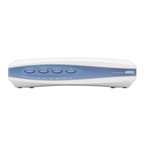
SHDSL 2-Wire/4-Wire Line Terminating Unit (LTU) INTRODUCTION ® This practice is an installation and maintenance guide for the ADTRAN Model 6543 SHDSL 2-Wire/4-Wire Line Terminating Unit (LTU), P/N 1230011L1. Figure 1 shows the SHDSL 2- Wire/4-Wire LTU. Express 6500 Series SHDSL G.703... -
Page 8: Compatibility
SHDSL 2-Wire/4-Wire Line Terminating Unit (LTU) Installation and Maintenance Practice VT100 VT100 2 – 4-Wire Twisted Pair Customer E1 Customer E1 Equipment Equipment (e.g., PABX) (e.g., PABX) SHDSL 2W/4W SHDSL 2W/4W Figure 2. Typical System Application Compatibility The SHDSL 2-Wire/4-Wire LTU is compatible with the following NTU products: Table 1. -
Page 9: Shdsl 2-Wire/4-Wire Mode, Line Rate
Introduction SHDSL 2-Wire/4-Wire Mode, Line Rate The SHDSL 2-Wire/4-Wire LTU supports multi-rate line operation (refer to Table Table 2. 2-Wire/4-Wire Multi-Rate Operation Data Rate Type 2-Wire Mode 4-Wire Mode 200 kbps to 2.312 Mbps (N × 64 400 kbps to 4.624 Mbps (N × 64 kbps + SHDSL Line Aggregate Data Rate kbps + 8 kbps, where N = 3 to 36) -
Page 10: Features
SHDSL 2-Wire/4-Wire Line Terminating Unit (LTU) Installation and Maintenance Practice Features Table 3 lists the product features of the SHDSL 2-Wire/4-Wire LTU. Table 3. Product Feature Set SHDSL 2-Wire/4-Wire LTU Feature Set Physical Description Net Housing: 5.3 cm (2.1 in.) H x 23.6 cm (9.3 in.) W x 16.8 cm (6.6 in.) D Front Panel Recessed Pushbuttons (4 total) PORT SELECT LOCAL LOOP/ERR INJ... -
Page 11: Compliance
1. This device may not cause harmful interference. 2. This device must accept any interference received, including interference that may cause undesired operation. Changes or modifications not expressly approved by ADTRAN could void the user’s authority to operate this equipment. 61230011L1-5B... -
Page 12: Installation
HANDLING PRECAUTIONS REQUIRED. After unpacking the SHDSL 2-Wire/4-Wire LTU, inspect it for damage. If damage has occurred, file a claim with the carrier, then contact ADTRAN Customer Service. Refer to “Appendix A, Warranty” for further information. If possible, keep the original shipping container for returning the unit for repair or for verification of shipping damage. -
Page 13: Front Panel Leds
The front panel has LED status indicators that match the specific feature set of the model. Table 5 on page 8 details LED functionality. Figure 4 illustrates the location of each LED on the front panel. Express 6500 Series SHDSL G.703 Nx64K BERT... -
Page 14: Table 5. Led Indicator Functionality
SHDSL 2-Wire/4-Wire Line Terminating Unit (LTU) Installation and Maintenance Practice Table 5. LED Indicator Functionality Label Status Description Unit is not powered Green Unit is powered Unit is powered off SHDSL Green Port is trained; no active alarms Yellow Port is trained with a minor active alarm Port is attempting to or is trained with a major alarm Port is not active G.703... -
Page 15: Pushbutton And Led Indicator Interaction
Installation Pushbutton and LED Indicator Interaction The following is a further explanation of the required interaction between the front panel pushbuttons and LEDs. When no port is selected, (no flashing port LEDs) only the pushbutton is PORT SELECT enabled, and the , and LEDs indicate the status (refer to Table... -
Page 16: Connections
SHDSL 2-Wire/4-Wire Line Terminating Unit (LTU) Installation and Maintenance Practice CONNECTIONS Rear Panel The SHDSL 2-Wire/4-Wire LTU does not have a power switch. A rear panel is designed with connections and labeling (refer to Table Figure 5 illustrates the SHDSL 2-Wire/4-Wire LTU rear panel. -
Page 17: Power Supply
Connections Power Supply The SHDSL 2-Wire/4-Wire LTU supports Terminal Block, Span or DC powering. DC Powering Physical connection for DC operation is made on a 4-pin terminal block, shrouded male recep- tacle. The DC model operates over a DC input range of ±42 VDC to ±56 VDC (–48 VDC nominal), with a power rating not to exceed ten watts. -
Page 18: G.703 Pinout
SHDSL 2-Wire/4-Wire Line Terminating Unit (LTU) Installation and Maintenance Practice G.703 Pinout The G.703 port is SELV rated with a rear panel connection of either a 120Ω balanced RJ-45 jack with signals and pinouts (refer to Table Table 9. G.703 Port RJ-45 Pinouts Circuit Name Function... -
Page 19: Optioning
Optioning OPTIONING Timeslot Cross-Connect Map The SHDSL 2-Wire/4-Wire LTU supports the configuration of multiple services. A service is comprised of an arbitrary collection of timeslots from the SHDSL interface that are configured through the management interface. These services are routed to the G.703 interface. -
Page 20: Menu Tree
SHDSL 2-Wire/4-Wire Line Terminating Unit (LTU) Installation and Maintenance Practice G.703 Rx/Tx CLK SHDSL Ext Tx CLK G.703 Port Tx CLK Rx Clk Sel Rx CLK 2-Wire or Rx Clk 4-Wire Select Internal Loop SHDSL Port Clock Recovery G.703 Port Figure 6. -
Page 21: Figure 7. 6500 Series Menu Tree
Optioning 1. LTU 1. Unit Information 1. Cross-Connect Map 1. 2-Wire 2. NTU 1. Internal Clock 1. Interface Mode 2. Clock Source 2. 4-Wire Main Menu 2. G.703 Rx Clock 1. Unit Options 3. Circuit ID 2. Payload Rate (kbps) * 3. -
Page 22: Troubleshooting
SHDSL 2-Wire/4-Wire Line Terminating Unit (LTU) Installation and Maintenance Practice TROUBLESHOOTING Local and Remote Loopbacks for Ports and Services For troubleshooting purposes, the SHDSL 2-Wire/4-Wire LTU provides five types of loopback tests for each interface port and each data service. •... -
Page 23: Table 10. Loopback Test Summary
Troubleshooting Table 10. Loopback Test Summary Initiating Source SHDSL Port G.703 Port G.703 Service Proprietary EOC Local Loopback Request Message ACTIVATE (Initiates one of five loopback types, regardless of the associated Loopback Type Option setting.) Proprietary EOC Local Loopback Request Message DEACTIVATE Proprietary EOC Remote Inband Request Sends... - Page 24 SHDSL 2-Wire/4-Wire Line Terminating Unit (LTU) Installation and Maintenance Practice Table 10. Loopback Test Summary (Continued) Initiating Source SHDSL Port G.703 Port G.703 Service VT100 Remote Loopback OFF Front Panel Pushbuttons Local Loop Pushbutton ON (Initiates a Local Single Loopback per the associated port/service Service Loopback Type Option setting.) Only...
-
Page 25: Bit Error Rate Tester (Bert)
Troubleshooting Table 11. KEY to Symbols used in Table 10 Directions Loopbacks No Loop Dual Sided Customer (to NTU) Customer Transparent Network Transparent Network (to LTU) Customer Non-Transparent Network Non-Transparent Bit Error Rate Tester (BERT) The SHDSL 2-Wire/4-Wire LTU provides an internal bit error rate tester (BERT) for the injection and observation of a pseudo-random bit sequence (PRBS) to and from the SHDSL interface on a per service basis. -
Page 26: Bert Application
SHDSL 2-Wire/4-Wire Line Terminating Unit (LTU) Installation and Maintenance Practice BERT Application In a typical testing scenario, a remote loopback or remote BERT is active in conjunction with the locally active BERT (refer to Figure 8 Figure Local Unit Remote Unit SHDSL PRS Controller V.54/PN127 Controller... -
Page 27: Bad Splice Detection (Tscan)
Troubleshooting Bad Splice Detection (TScan) The SHDSL 2-Wire/4-Wire LTU provides bad splice protection using the ADTRAN proprietary ™ Runtime TScan 2.0 splice protection feature. TScan splice detection is a non-intrusive algorithm that enables the SHDSL 2-Wire/4-Wire LTU to detect anomalies (bad splices) in the copper pair. -
Page 28: Figure 10. Bad Splice Detection (Tscan) Menu
SHDSL 2-Wire/4-Wire Line Terminating Unit (LTU) Installation and Maintenance Practice • If more than one count register exceeds the threshold, then the count that is larger displays as a bad splice. • If two or more count register exceed the threshold and are of equal count, then the distance count closest to the unit displays as a bad splice because the detector is more accurate the closer the anomaly is to the unit. -
Page 29: Restart Bad Splice Detector Screen
Troubleshooting Restart Bad Splice Detector Screen Configuration The Restart Bad Splice Detector screen (Figure 11) enables a reset of the 24 hour count history. NOTE The SHDSL 2-Wire/4-Wire LTU also clears the count history automatically on power-up. Unit Mode: 21-Nov-06 11:01:32 Circuit ID: Terminal Mode: Local Restart Bad Splice Detector... -
Page 30: Bad Splice Detection (Tscan) 24 Hour Counts Screen
SHDSL 2-Wire/4-Wire Line Terminating Unit (LTU) Installation and Maintenance Practice Bad Splice Detection (TSCAN) 24 Hour Counts Screen Provisioning The Bad Splice (TSCAN) 24 Hour Counts screen displays the history register. If the unit is handshaking or training, the splice loop rates and count registers do not update. If the unit is trained, it updates the splice current day data registers. -
Page 31: Specifications
Specifications SPECIFICATIONS Table 14 lists the specifications for the SHDSL 2-Wire/4-Wire Line Terminating Unit (LTU) Table 14. SHDSL 2-Wire/4-Wire Line Terminating Unit (LTU) Specifications Specification Description Environmental Operating Temperature: –5°C to +55°C Storage Temperature: –25°C to +70°C Relative Humidity: 90 percent maximum @ 50°C, noncondensing Maximum Current Draw: 250 mA @ –... - Page 32 SHDSL 2-Wire/4-Wire Line Terminating Unit (LTU) Installation and Maintenance Practice This page is intentionally blank. 61230011L1-5B...
-
Page 33: Warranty
Appendix A Warranty WARRANTY AND CUSTOMER SERVICE ADTRAN will replace or repair this product within the warranty period if it does not meet its published specifications or fails while in service. Warranty information can be found at www.adtran.com/warranty. Refer to the following subsections for sales, support, Customer and Product Service (CAPS) requests, or further information. - Page 34 ® Carrier Networks Division 901 Explorer Blvd. Huntsville, AL 35806...
Need help?
Do you have a question about the Express 6500 Series and is the answer not in the manual?
Questions and answers