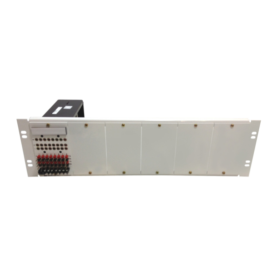
ADC Cross-Connect DSX-1 Operational Procedures Manual
Hide thumbs
Also See for Cross-Connect DSX-1:
- User manual (13 pages) ,
- User manual (11 pages) ,
- Quick start manual (9 pages)
Table of Contents
Advertisement
Quick Links
ADCP-80-514 • Issue 1 • January 1999
DSX-1 Cross-Connect
Operational Procedures
INTRODUCTION .................................................................. 2
TRANSMISSION SIGNAL DIRECTION .................................................... 3
TRANSMISSION PATH - NORMAL ...................................................... 4
TRANSMISSION PATH - PATCHED ...................................................... 5
TRANSMISSION PATH - TERMINATED.................................................... 6
RECOMMENDED CROSS-CONNECT ROUTING ............................................... 7
IN-SERVICE PATCHING ............................................................. 8
OUT-OF-SERVICE PATCHING.......................................................... 9
RESTORATION USING A MAINTENANCE LINE ...............................................10
CROSS-CONNECT REARRANGEMENT (EXAMPLE: OFFICE CONVERSION) ............................11
INTERBAY PATCH ARRANGEMENT ......................................................12
TYPICAL CROSS-AISLE TIE ARRANGEMENT................................................13
TYPICAL REPEATERED CROSS-AISLE TIE ARRANGEMENT ......................................13
GENERAL INFORMATION ............................................................14
1040851 Rev A
Page 1
© 1999, ADC Telecommunications, Inc.
Advertisement
Table of Contents

Summary of Contents for ADC Cross-Connect DSX-1
-
Page 1: Table Of Contents
OUT-OF-SERVICE PATCHING............9 RESTORATION USING A MAINTENANCE LINE ..........10 CROSS-CONNECT REARRANGEMENT (EXAMPLE: OFFICE CONVERSION) ......11 INTERBAY PATCH ARRANGEMENT ............12 TYPICAL CROSS-AISLE TIE ARRANGEMENT..........13 TYPICAL REPEATERED CROSS-AISLE TIE ARRANGEMENT ........13 GENERAL INFORMATION ............14 1040851 Rev A Page 1 © 1999, ADC Telecommunications, Inc. -
Page 2: Introduction
INTRODUCTION This manual provides operation procedures for use with any ADC DSX-1 cross-connect system. The procedures are illustrated with a generic circuit diagram that can be applied to any DSX-1 circuit module. The diagram indicates that some features such as a Monitor In (MON IN) jack may or may not be present. -
Page 3: Transmission Signal Direction
RECEIVE (IF PRESENT) 5-CONDUCTOR (IF PRESENT) JUMPER WIRE (4- WITHOUT TL) (IF PRESENT) (IF PRESENT) GREEN GREEN BLUE BLUE BLUE-WHITE BLUE-WHITE ORANGE ORANGE 11885-B ORANGE-WHITE ORANGE-WHITE TWISTED TWISTED PAIR PAIR TRANSMISSION SIGNAL DIRECTION Page 3 © 1999, ADC Telecommunications, Inc. -
Page 4: Transmission Path-Normal
ADCP-80-514 • Issue 1 • January 1999 JACK FIELD (IF PRESENT) TRACER LED -48V -48V IN/OUT TERMINAL BLOCK TRANSMIT EQUIPMENT CABLES TERMINATE HERE RECEIVE (IF PRESENT) CROSS-CONNECT TERMINAL BLOCK TRACER 5-WIRE CROSS-CONNECT TRANS 11886-B JUMPERS TERMINATE HERE TRANSMISSION PATH—NORMAL Page 4 © 1999, ADC Telecommunications, Inc. -
Page 5: Transmission Path-Patched
TRACER LED -48V -48V IN/OUT TERMINAL BLOCK PATCH TRANSMIT CORD PATCH RECEIVE CORD (IF PRESENT) CROSS-CONNECT TERMINAL BLOCK TRACER TRANSMISSION PATH THROUGH THE CROSS- TRANS 11887-B CONNECT PATH IS NOW OPEN TRANSMISSION PATH—PATCHED Page 5 © 1999, ADC Telecommunications, Inc. -
Page 6: Transmission Path-Terminated
ADCP-80-514 • Issue 1 • January 1999 JACK FIELD (IF PRESENT) TRACER LED -48V -48V TERMINATION IN/OUT TERMINAL BLOCK PLUG TERMINATED TRANSMIT RECEIVE (IF PRESENT) CROSS-CONNECT TERMINAL BLOCK TRACER TRANS OPEN 11888-B TRANSMISSION PATH—TERMINATED Page 6 © 1999, ADC Telecommunications, Inc. -
Page 7: Recommended Cross-Connect Routing
All jumpers originating in the lower half of the cross-connect field should route via the lower horizontal wireways. LOWER JUMPER WIREWAYS 3354-A RECOMMENDED CROSS-CONNECT ROUTING Page 7 © 1999, ADC Telecommunications, Inc. -
Page 8: In-Service Patching
Standby Facility DSX OUT jack first to avoid interrupting service. Step 4. Terminate the DSX OUT jacks at each office. Note: The patch cords should be removed from the Equipment end first during restoral. IN-SERVICE PATCHING Page 8 © 1999, ADC Telecommunications, Inc. -
Page 9: Out-Of-Service Patching
Equipment C. FACILITY TRANSMIT Note: The patch cords should be removed from the Equipment C end first during restoral. RECEIVE (IF PRESENT) (IF PRESENT) GREEN BLUE BLUE-WHITE 11890-B ORANGE ORANGE-WHITE OUT-OF-SERVICE PATCHING Page 9 © 1999, ADC Telecommunications, Inc. -
Page 10: Restoration Using A Maintenance Line
Caution: For in-service patching, each step must be completed at both offices before proceeding to the next step. Note: Bridging Repeaters are located in the Office Repeater Bay as part of the Maintenance Line. RESTORATION USING A MAINTENANCE LINE Page 10 © 1999, ADC Telecommunications, Inc. -
Page 11: Cross-Connect Rearrangement (Example: Office Conversion)
Step 3. Wire new cross-connects between Equipment B and (EQUIPMENT B) Equipment C. Step 4. Remove patch cords. RECEIVE (IF PRESENT) (IF PRESENT) GREEN BLUE BLUE-WHITE 11889-B ORANGE ORANGE-WHITE CROSS-CONNECT REARRANGEMENT (EXAMPLE: OFFICE CONVERSION) Page 11 © 1999, ADC Telecommunications, Inc. -
Page 12: Interbay Patch Arrangement
The reverse is true if patch is made from right to left direction. Note: In this example, the LEDs in Bay 7 and 11 for Circuit 3 will be lit, indicating the jack is in use. 11891-B INTERBAY PATCH ARRANGEMENT Page 12 © 1999, ADC Telecommunications, Inc. -
Page 13: Typical Cross-Aisle Tie Arrangement
(220 - 440 ft.) (220 - 440 ft.) 134.11 M - 199.64 M 134.11 M - 199.64 M (440 - 655 ft.) (440 - 655 ft.) 366 M MAXIMUM 8649-D TYPICAL REPEATERED CROSS-AISLE TIE ARRANGEMENT Page 13 © 1999, ADC Telecommunications, Inc. -
Page 14: General Information
Inc., P.O. Box 1101, Minneapolis, MN 55440-1101, U.S.A. Contents herein are current as of the date of publication. ADC reserves the right to change the contents without prior notice. In no event shall ADC be liable for any damages resulting from loss of data, loss of use, or loss of profits and ADC further disclaims any and all liability for indirect, incidental, special, consequential or other similar damages.


Need help?
Do you have a question about the Cross-Connect DSX-1 and is the answer not in the manual?
Questions and answers