ADC Digivance Installation And Operation Manual
Indoor coverage solution 800 mhz single- or multi-mode fiber system
Hide thumbs
Also See for Digivance:
- Installation and operation manual (34 pages) ,
- User manual (32 pages) ,
- Installation and operation manual (30 pages)

Related Manuals for ADC Digivance


Summary of Contents for ADC Digivance
- Page 1 Preliminary ADCP-75-130 Preliminary Issue 3C August 2006 ® Digivance Indoor Coverage Solution 800 MHz Single- or Multi-Mode Fiber System Installation and Operation Manual 1371998 Rev 1...
- Page 3 ADCP-75-130 Preliminary Issue 3C August 2006 ® Digivance Indoor Coverage Solution 800 MHz Single or Multi-Mode Fiber System Installation and Operation Manual 1371998 Rev 1...
- Page 4 Contents herein are current as of the date of publication. ADC reserves the right to change the contents without prior notice. In no event shall ADC be liable for any damages resulting from loss of data, loss of use, or loss of profits and ADC further disclaims any and all liability for indirect, incidental, special, consequential or other similar damages.
-
Page 5: Table Of Contents
4.10 External Alarm System Connections ..........38 4.11 AC Power Connections ............39 4.12 Create As-Built Drawing ............40 SYSTEM OPERATION ..............41 Tools and Materials............. 41 Turn-Up System and Verify Operation ..........41 (continued) Page iii © 2006, ADC Telecommunications, Inc. - Page 6 DRU Modular Optical Transceiver Replacement Proceudre ........61 GENERAL INFORMATION............... 64 Warranty/Software ............. 64 Software Service Agreement ............64 Repair/Exchange Policy............64 Repair Charges ............... 65 Replacement/Spare Products ............65 Returned Material ............. 65 Customer Information and Assistance ..........66 Page iv © 2006, ADC Telecommunications, Inc.
- Page 7 RELATED PUBLICATIONS Listed below are related manuals and their publication numbers. Copies of these publications can be ordered by contacting the ADC Technical Assistance Center at 1-800-366-3891, extension 73476 (in U.S.A. or Canada) or 952-917-3476, (outside U.S.A. and Canada). Title/Description...
- Page 8 Warning: Do not install the DRU in marine, industrial, or Intrinsic Safety (IS) environments without an engineering review of the air quality including the presence of other constituent gasses and dusts. Contact ADC for application assistance if necessary. Warning: The DRU is powered by 48 VDC power which is supplied over customer-provided wiring.
- Page 9 Automatic Gain Control AMPS Advanced Mobile Phone Service Base Transceiver Station CDMA Code Division Multiple Access CDRH Center for Devices and Radiological Health Canadian Electrical Code Underwriters’ Laboratories of Canada Distributed Antenna System Page vii © 2006, ADC Telecommunications, Inc.
- Page 10 RSSI Received Signal Strength Indication Receive or Receiver Single-Mode TDMA Time Division Multiple Access Transmit or Transmitter Underwriters’ Laboratories Uninterruptible Power Supply Volts Volts Alternating Current Volts Direct Current WECO Western Electric Company Page viii © 2006, ADC Telecommunications, Inc.
-
Page 11: System Functional Overview
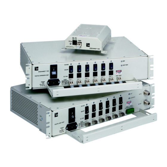
1.1 Basic System Components The basic components of the Digivance ICS and their functions are shown in Figure 1. The basic system consists of the Digital Host Unit (DHU), Digital Remote Unit (DRU), and when additional capacity or longer fiber runs are required, the Digital Expansion Unit (DEU). -
Page 12: Digital Fiber Optic Transport
DRU or the DHU as long as the BER is adequate. Either 62.5 or 50 micron core multi-mode optical fiber; or 9 micron core single-mode optical fiber may be used for the Page 2 © 2006, ADC Telecommunications, Inc. -
Page 13: Capacity For Expansion And Extended Runs
ICS system, a listing of terms used and their definition, and a table of specifications. 2.1 Digital Host Unit Description The DHU, shown in Figure 2, serves as the BTS servicing unit for the Digivance ICS. The DHU provides the following basic functions: •... - Page 14 DHU to be mounted on any flat vertical surface. The DHU should be oriented with the front panel facing upward when wall-mounted. Fasteners are provided for rack-mount applications. Page 4 © 2006, ADC Telecommunications, Inc.
- Page 15 RIU or the HPCP. Additional information concerning the DHU to BTS interface is provided in the Digivance ICS Remote Interface Unit User Manual (ADCP- 75-178) and in the Digivance ICS 800 and 1900 MHz High Power Conditioning Panel User Manual (ADCP-75-175).
- Page 16 DHU. RF OUT N-type female RF Used for connecting the reverse path RF coaxial connector coaxial cable to the DHU. Note: A more detailed description of LED operation is provided in Section 5. Page 6 © 2006, ADC Telecommunications, Inc.
-
Page 17: Digital Remote Unit Description
17264-A Figure 3. Digital Host Unit User Interface 2.2 Digital Remote Unit Description The DRU, shown in Figure 4, serves as the remote interface unit for the Digivance ICS. The DRU provides the following basic functions: • RF interface to the cellular users via an external antenna •... - Page 18 An SMA connector is provided for connecting the DRU to the antenna. The antenna must be ordered separately. Several types of antennas with various RF propagations are available. Non-ADC antennas may also be used with the DRU to meet various application requirements but must comply with equipment authorization for RF exposure compliance.
- Page 19 Note: A more detailed description of LED operation is provided in Section 5. (2) 48 VDC POWER (3) FIBER LINK CONNECTOR OPTICAL ADAPTERS TX-LEFT - RX-RIGHT FRONT VIEW REAR VIEW 17269-A (1) STATUS LED (4) ANTENNA CONNECTOR Figure 5. Digital Remote Unit User Interface Page 9 © 2006, ADC Telecommunications, Inc.
-
Page 20: Digital Expansion Unit Description
2.3 Digital Expansion Unit Description The DEU, shown in Figure 6, serves as a service expansion unit and line extender for the Digivance ICS. The DEU provides the following basic functions: • Optical interface to the DHU and up to six DRU’s or DEU’s •... - Page 21 The DEU user interface consists of the various connectors, switches, and LEDs that are provided on the DEU front panel. The DEU user interface points are described in Table 3 and indicated in Figure 7. Page 11 © 2006, ADC Telecommunications, Inc.
- Page 22 CONNECTOR DC POWER JACK OPTICAL TRANSCEIVER OPTICAL TRANSCEIVER (6 PLACES) TX-LEFT - RX-RIGHT TX-LEFT - RX-RIGHT INDICATOR NOTE: SHOWN WITHOUT (6 PLACES) CABLE MANAGEMENT TRAY 17266-A Figure 7. Digital Expansion Unit User Interface Page 12 © 2006, ADC Telecommunications, Inc.
-
Page 23: Terms And Definitions
Unit Alarm A fault within a unit that usually affects all connected ports. 2.5 Specifications Refer to Table 5 for the Digivance ICS system specifications. All specifications apply after a five minute warm-up period. Page 13 © 2006, ADC Telecommunications, Inc. - Page 24 Over frequency, temperature, and < 1.5 dB variation per 1.25 MHz unit to unit. CDMA channel Automatic Gain Limiting Enabled for composite RF input Prevents A/D saturation with large > –40 dBm inputs. (continued) Page 14 © 2006, ADC Telecommunications, Inc.
-
Page 25: Ac Power Connections
Note : The noise from all remotes is added at the host. Given N units with identical gain and noise, the formula applies exactly. Slight unit to unit noise figure and gain variations make this a very useful approximation. Page 15 © 2006, ADC Telecommunications, Inc.
Need help?
Do you have a question about the Digivance and is the answer not in the manual?
Questions and answers