Table of Contents
Advertisement
Advertisement
Table of Contents

Related Manuals for Cisco Rugged Series


Summary of Contents for Cisco Rugged Series
- Page 1 Cisco Catalyst IR8340 Rugged Series Router Hardware Installation Guide First Published: 2022-05-26 Last Modified: 2022-07-28 Americas Headquarters Cisco Systems, Inc. 170 West Tasman Drive San Jose, CA 95134-1706 http://www.cisco.com Tel: 408 526-4000 800 553-NETS (6387) Fax: 408 527-0883...
- Page 2 Cisco has more than 200 offices worldwide. Addresses and phone numbers are listed on the Cisco website at www.cisco.com/go/offices. Cisco and the Cisco logo are trademarks or registered trademarks of Cisco and/or its affiliates in the U.S. and other countries. To view a list of Cisco trademarks, go to this URL: https://www.cisco.com/c/en/us/about/legal/trademarks.html.
-
Page 3: Table Of Contents
Hardware Features Alarm Ports Alarm Input Alarm Output Console Port Power-Input Terminal 100/1000 SFP Ports (Uplinks) 100/1000 SFP Ports (Downlinks) 10/100/1000 PoE/PoE+/UPoE Ports (Downlinks) mSATA Module Timing Module SD Flash Memory Card Cisco Catalyst IR8340 Rugged Series Router Hardware Installation Guide... - Page 4 Safety Warnings Statement 191—Voluntary Control Council for Interference (VCCI) Class A Warning for Japan ステートメント 191—日本向け VCCI クラス A に関する警告 Statement 1008—Class 1 Laser Product ステートメント 1008—クラス 1 レーザー製品 Before You Begin Cisco Catalyst IR8340 Rugged Series Router Hardware Installation Guide...
- Page 5 C H A P T E R 5 Installing and Upgrading Modules Safety Warnings Installing a Network Interface Module in the IR8340 Router Installing Pluggable Modules Installing the mSATA SSD Installing SFP Modules Laser Safety Guidelines Cisco Catalyst IR8340 Rugged Series Router Hardware Installation Guide...
- Page 6 Console Port Alarm Port Cables and Adapters SFP Module Cables Console Port Adapter Pinouts C H A P T E R 8 Technical Specifications Router Specifications Power-Supply Module Specifications Alarm Ratings Cisco Catalyst IR8340 Rugged Series Router Hardware Installation Guide...
-
Page 7: Preface
Communications, Services, and Additional Information, on page xiv Objective This guide provides an overview and explains how to install and connect your Cisco device. Audience This guide is intended for people who have a high level of technical ability, although they may not have experience with Cisco software. -
Page 8: Safety Warnings
Gebruik het nummer van de verklaring onderaan de waarschuwing als u een vertaling van de waarschuwing die bij het apparaat wordt geleverd, wilt raadplegen. BEWAAR DEZE INSTRUCTIES Cisco Catalyst IR8340 Rugged Series Router Hardware Installation Guide viii... - Page 9 å forhindre ulykker. Bruk nummeret i slutten av hver advarsel for å finne oversettelsen i de oversatte sikkerhetsadvarslene som fulgte med denne enheten. TA VARE PÅ DISSE INSTRUKSJONENE Cisco Catalyst IR8340 Rugged Series Router Hardware Installation Guide...
- Page 10 Använd det nummer som finns i slutet av varje varning för att hitta dess översättning i de översatta säkerhetsvarningar som medföljer denna anordning. SPARA DESSA ANVISNINGAR Cisco Catalyst IR8340 Rugged Series Router Hardware Installation Guide...
- Page 11 Brug erklæringsnummeret efter hver advarsel for at finde oversættelsen i de oversatte advarsler, der fulgte med denne enhed. GEM DISSE ANVISNINGER Cisco Catalyst IR8340 Rugged Series Router Hardware Installation Guide...
- Page 12 Law prohibits the use of UL-certified cables (that have the “UL” shown on the code) for any other electrical devices than products designated by CISCO. The use of cables that are certified by Electrical Appliance and Material Safety Law (that have “PSE” shown on the code) is not limited to CISCO-designated products.
-
Page 13: Related Documentation
The covers are an integral part of the safety design of the product. Do not operate the unit without the covers installed. Statement 1077 Warning Hot surface. Statement 1079 Related Documentation All of the IR8340 documentation can be found online here: https://www.cisco.com/c/en/us/support/routers/catalyst-ir8300-rugged-series-router/series.html Cisco Catalyst IR8340 Rugged Series Router Hardware Installation Guide xiii... -
Page 14: Communications, Services, And Additional Information
Cisco Bug Search Tool (BST) is a gateway to the Cisco bug-tracking system, which maintains a comprehensive list of defects and vulnerabilities in Cisco products and software. The BST provides you with detailed defect information about your products and software. -
Page 15: Product Overview
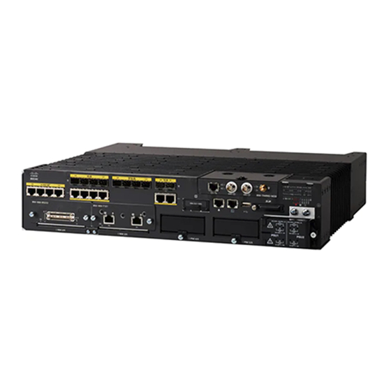
C H A P T E R Product Overview Cisco Catalyst IR8340 Rugged Series Router is an industrial grade routing platform with higher port density, higher throughput, native FOG computing, compute capabilities, and enhanced security functionalities. These topics are discussed: •... -
Page 16: Alarm Ports
You can use the CLI to set the alarm severity to minor, or major. An alarm generates a system message and turns on an LED. See Cable Side View LEDs, on page 11 for the LED descriptions. Cisco Catalyst IR8340 Rugged Series Router Hardware Installation Guide... -
Page 17: Alarm Output
For information about SFP modules, see your SFP module documentation. For more information about SFP modules and cables, see Transceiver Modules The small form factor pluggable (SFP) ports on the Cisco IR8340 router support the following SFP modules: Table 1: Supported SFP Modules Part Number... -
Page 18: 10/100/1000 Poe/Poe+/Upoe Ports (Downlinks)
The 10/100/1000 PoE ports on the router provide PoE support for devices that are compliant with IEEE 802.3af/802.3at. The Cisco prestandard PoE is also supported for Cisco IP Phones and Cisco Aironet Access Points. The PoE ports on the router deliver up to 30 W of PoE+ power. All four ports are PoE ports and can be assigned a port priority. -
Page 19: Msata Module
(SSDs). The Cisco IR8340 router provides an expand slot to accommodate the mSATA module (PID: IRM-SSD-100G). The following figure shows the mSATA Pluggable Module. -
Page 20: Sd Flash Memory Card
SD Flash Memory Card The Cisco IR8340 router supports a flash memory card that makes it possible to replace a failed router without reconfiguring the new router. The slot for the flash memory card is on the front of the router. The flash card is hot swappable and can be accessed on the front panel in non hazardous locations only. -
Page 21: Pluggable Lte Module
• All Cellular interfaces are supported through a pluggable module. • Micro-Sim, 3FF size. Cisco recommends Industrial Temp micro SIMs that are rated from -40 to +105°C. The following two figures show an example of a pluggable module. In this case, the LTE Pluggable Module. -
Page 22: Lte Category 18 Pluggable Module
Figure 6: LTE Pluggable Module (With Antennas) LTE Category 18 Pluggable Module This module has a new smaller form factor SMA Diversity Antenna for usability and Micro-USB port access. Figure 7: LTE Pluggable P-LTEAP18-GL Cisco Catalyst IR8340 Rugged Series Router Hardware Installation Guide... -
Page 23: 5G Pluggable Interface Module
• The capability to disable FDD Band 30 for vehicular applications is available. The following figure shows the P-5GS6-GL pluggable module: Cisco Catalyst IR8340 Rugged Series Router Hardware Installation Guide... -
Page 24: Supported Cisco Antennas And Antenna Accessories
The Antenna Selection and Installation chapter lists the supported Antennas and Accessories for the Cisco IR8340 router with a wireless Pluggable Module. For detailed information about Cisco Antennas for the... -
Page 25: Cable Side View Leds
Any port on the module presents failure. Not present or not powered. Present and operating. PIM 0 Green PIM 1 Amber Any port on the module presents failure. Not present or not powered. Cisco Catalyst IR8340 Rugged Series Router Hardware Installation Guide... - Page 26 Blinking green Attempting to acquire satellite fix. Blinking amber Antenna fault. GPS is not configured. ALARMS IN 1-2 Green No alarm. Solid red Major alarm present. Blinking red Critical alarm present. Cisco Catalyst IR8340 Rugged Series Router Hardware Installation Guide...
-
Page 27: Power Supply Side View
Green Port is delivering power. Amber PoE is enabled with failure. Power Supply Side View The power-supply side has the LED panel and two power-supply slots for the removable power supplies. Cisco Catalyst IR8340 Rugged Series Router Hardware Installation Guide... -
Page 28: Power Supply Features
The router supports these power-supply module combinations: • Single low-voltage DC • Single high-voltage DC or AC • Two high-voltage DC or AC • Two low-voltage DC • One high-voltage DC or AC and one low-voltage DC Cisco Catalyst IR8340 Rugged Series Router Hardware Installation Guide... -
Page 29: Preparing For Router Installation
• Look carefully for possible hazards in your work area, such as moist floors, ungrounded power extension cables, frayed power cords, and missing safety grounds. • Do not work alone if hazardous conditions exist. Cisco Catalyst IR8340 Rugged Series Router Hardware Installation Guide... -
Page 30: Preventing Electrostatic Discharge Damage
Ensure that the site is properly prepared before beginning installation. If you are experiencing shutdowns or unusually high errors with your existing equipment, this section can also help you isolate the cause of failures and prevent future problems. Cisco Catalyst IR8340 Rugged Series Router Hardware Installation Guide... -
Page 31: Rack Requirements
Router Environmental Requirements Mount the Cisco IR8340 routers in a rack. The location of your router and the layout of your equipment rack or wiring room are extremely important considerations for proper operation. Equipment placed too close together, inadequate ventilation, and inaccessible panels can cause malfunctions and shutdowns, and can make maintenance difficult. -
Page 32: Network Cabling Specifications
Network Cabling Specifications Caution Two types of power supplies are supported on the Cisco IR8340: a low-voltage DC power supply and a high-voltage DC/AC power supply. Take caution when selecting the correct input voltage for the power supply installed or damage will result. - Page 33 The serial port can be configured as DTE or DCE, depending on the attached cable. All serial ports configured as DTE require external clocking from a CSU/DSU or other DCE device. Cisco Catalyst IR8340 Rugged Series Router Hardware Installation Guide...
-
Page 34: Required Tools And Equipment For Installation And Maintenance
• Cables for connection to the WAN and LAN ports (dependent on configuration). Ethernet hub or PC with a network interface card for connection to an Ethernet (LAN) port. Cisco Catalyst IR8340 Rugged Series Router Hardware Installation Guide... - Page 35 9600 baud, 8 data bits, 1 stop bit, no flow control, and no parity. Data service unit (DSU) or channel service unit/data service unit (CSU/DSU) as appropriate for serial interfaces. External CSU for any CT1/PRI modules without a built-in CSU. Cisco Catalyst IR8340 Rugged Series Router Hardware Installation Guide...
- Page 36 Preparing for Router Installation Required Tools and Equipment for Installation and Maintenance Cisco Catalyst IR8340 Rugged Series Router Hardware Installation Guide...
-
Page 37: Installing And Connecting The Router
For the optimum temperature ranges, do not operate it in an area that less than the minimum of -40°C and exceeds a maximum recommended ambient temperature of 60°C. Note To view specifications for the Cisco Catalyst IR8340 Rugged Series Router, see the IR8340 data sheet. Safety Warnings Warning Only trained and qualified personnel should be allowed to install, replace, or service this equipment. - Page 38 A ground wire must always be a single piece of wire. Never splice two wires together for a ground. Corrosion and weathering can lead to a poor connection at the splice, making the ground ineffective and dangerous. Statement 270 Cisco Catalyst IR8340 Rugged Series Router Hardware Installation Guide...
-
Page 39: Statement 191-Voluntary Control Council For Interference (Vcci) Class A Warning For Japan
This is a Class A product based on the standard of the VCCI Council. If this equipment is used in a domestic environment, radio interference may occur, in which case, you may be required to take corrective actions. Cisco Catalyst IR8340 Rugged Series Router Hardware Installation Guide... -
Page 40: ステートメント 191-日本向け Vcci クラス A に関する警告
ステートメント 1008 クラス 1 レーザー製品 警告 クラス 1 レーザー製品です。 Before You Begin Before installing and connecting a Cisco IR8340 router, read the safety warnings and gather the following tools and equipment: • ESD-preventive cord and wrist strap • Number 2 Phillips screwdriver •... -
Page 41: Installing The Router In A Rack
Allow at least one rack unit of vertical space above and below the router. Rack-Mounting the Chassis The Cisco IR8340 router can be installed in a 19-inch (48.26-cm) standard rack. It is required that at least one rack unit of vertical space is left empty above and below the router. - Page 42 Attach the second bracket to the opposite side of the chassis. Use a number 2 Phillips screwdriver to install the number-8 bracket screws. Caution Your chassis installation must allow unrestricted airflow for chassis cooling. Cisco Catalyst IR8340 Rugged Series Router Hardware Installation Guide...
-
Page 43: Mounting The Router In A Rack
The following figure shows the screw slots in the rack-mount brackets to use when you mount the router in the rack. Figure 14: Mounting Screw Slots Mounting screw slots (6) Replacing the SD Flash Memory Card Follow these steps to replace the SD flash memory card: Cisco Catalyst IR8340 Rugged Series Router Hardware Installation Guide... -
Page 44: Connecting The Console Port
Close the cover, and hand-tighten the screw. Connecting the Console Port To configure the router through the Cisco IOS command-line interface (CLI), you must establish a connection between the router console port and either a terminal or a PC. Console Port Connection to a PC To connect a PC terminal to the console port, use the RJ-45-to-RJ-45 rollover cable, and either the RJ-45-to-DB-25 female DTE adapter or the RJ-45-to-DB-9 female DTE adapter (labeled TERMINAL ). -
Page 45: Console Port Signaling And Cabling With A Db-25 Adapter
To avoid electric shock, do not connect safety extra-low voltage (SELV) circuits to telephone-network voltage (TNV) circuits. LAN ports contain SELV circuits, and WAN ports contain TNV circuits. Some LAN and WAN ports both use RJ-45 connectors. Use caution when connecting cables. Statement 1021 Cisco Catalyst IR8340 Rugged Series Router Hardware Installation Guide... -
Page 46: Connection Procedures And Precautions
Organize cables in bundles so that cables do not intertwine. Step 4 Inspect the cables to make sure that the routing and bend radius is satisfactory. Reposition cables, if necessary. Note Install cable ties in accordance with site requirements. Cisco Catalyst IR8340 Rugged Series Router Hardware Installation Guide... -
Page 47: Power Supply Installation
Description PWR-RGD-AC-DC High-voltage AC or DC, 100-240VAC 50-60Hz/100-250VDC input, 150 watt output PWR-RGD-LOW-DC Low-voltage DC, 24-60VDC input, 150 watt output PWR-RGD-AC-DC-250 High-voltage AC or DC, 100-240VAC 50-60Hz/100-250VDC input, 250 watt output Cisco Catalyst IR8340 Rugged Series Router Hardware Installation Guide... -
Page 48: Power-Supply Module Leds
The router power-supply module LEDs are labeled PSU1 and PSU2 (on the router) and PSU OK (on the power-supply module). They show whether power-supply modules 1 and 2 are receiving power. Table 6: Power Supply Module LEDs Color System Status Power-supply module (1 or 2) is not installed. Cisco Catalyst IR8340 Rugged Series Router Hardware Installation Guide... -
Page 49: Power-Supply Module Installation
This procedure is for installing a power-supply module in the PSU1 or PSU2 slot. Warning The covers are an integral part of the safety design of the product. Do not operate the unit without the covers installed. Statement 1077 Cisco Catalyst IR8340 Rugged Series Router Hardware Installation Guide... -
Page 50: Equipment That You Need
When installing or replacing the unit, the ground connection must always be made first and disconnected last. Statement 1046 Caution Follow the grounding procedure instructions, and use an appropriately Listed or certified lug (included with the router) for number-6 AWG wire and 10-32 ground-lug screws. Cisco Catalyst IR8340 Rugged Series Router Hardware Installation Guide... - Page 51 Insert the ground wire into the terminal lug, and crimp the terminal to the wire. (see the following figure). Figure 22: Crimping the Terminal Lug Step 4 Slide the ground screws from Step 1 through the terminal lug. Insert the ground screws into the opening on the cable side. Cisco Catalyst IR8340 Rugged Series Router Hardware Installation Guide...
-
Page 52: Installing The Power Supply Module In The Router
Insert the power supply module into the slot, and gently push it in. Make sure that the alignment tabs of the module fit into the chassis, as shown in the following figure. Cisco Catalyst IR8340 Rugged Series Router Hardware Installation Guide... -
Page 53: Installing The Dc Power Supply In The Router
Use a ratcheting torque screwdriver to torque each screw to 8–10 in-lb (4-6.5 in-lb for 250 W PSU). Wiring the Power Source Before you wire the power source, review these warnings: Cisco Catalyst IR8340 Rugged Series Router Hardware Installation Guide... - Page 54 Use a Phillips screwdriver to loosen the captive screw on the power-input terminal, and open the cover. Figure 23: Opening the Power-Input Terminal Cover The terminal screws labels are on the power-input terminal cover. See the following figure. Cisco Catalyst IR8340 Rugged Series Router Hardware Installation Guide...
- Page 55 Insert the wire into a spade terminal, and crimp it to the wire. You can also use a ring or flanged spade terminal as listed in Equipment That You Need, on page Cisco Catalyst IR8340 Rugged Series Router Hardware Installation Guide...
- Page 56 • Connect the positive wire into the terminal screw labeled “+” , and the negative wire into the terminal screw labeled “ ”. Low-voltage DC Power-Supply Module • Connect the wires to the terminals labeled Lo. High-voltage DC Power-Supply Module • Connect the wires to the terminals labeled Hi. Cisco Catalyst IR8340 Rugged Series Router Hardware Installation Guide...
- Page 57 Verify that the PSU1 or PSU2 LED on the router and PSU OK LED on the power-supply module are green. See the router software guide for information on how to configure the power supply settings. Cisco Catalyst IR8340 Rugged Series Router Hardware Installation Guide...
-
Page 58: Removing The Power Supply Module
To prevent exposure to hazardous voltages and to contain electromagnetic interference (EMI), either a Caution power-supply module or a blank cover must be in each power-supply module slot at all times. Cisco Catalyst IR8340 Rugged Series Router Hardware Installation Guide... -
Page 59: Installing And Upgrading Modules
C H A P T E R Installing and Upgrading Modules This chapter describes how to install and upgrade modules in the Cisco Catalyst IR8340 Rugged Series Router in the following sections: Note Before you perform any module replacement, read... -
Page 60: Installing A Network Interface Module In The Ir8340 Router
After the module is properly inserted, tighten the module plate to the router with the two captive screws. The screws should be torqued to 5 to 7 in-lbs. Step 5 Connect the module to the network and re-enable the power to the slot in the router. Cisco Catalyst IR8340 Rugged Series Router Hardware Installation Guide... -
Page 61: Installing Pluggable Modules
Step 4 Install your SIMs (1) as shown in the following figure. Make note of the proper slot number and SIM orientation. Cisco Catalyst IR8340 Rugged Series Router Hardware Installation Guide... - Page 62 USB port (2). The half circle of the USB cover fits behind the latch lock screw, as shown in the following figure. Step 7 Tighten the latch lock screw to a torque of 2.8 to 3.8 in-lbs. The following figure shows a completed USB cover installation. Cisco Catalyst IR8340 Rugged Series Router Hardware Installation Guide...
-
Page 63: Installing The Msata Ssd
Mini-SATA, or mSATA, is a low-profile interface connector that enables more effective Serial ATA (SATA) integration in small form-factor drives roughly the size of a business card, such as solid state disks (SSDs). Cisco Catalyst IR8340 Rugged Series Router Hardware Installation Guide... -
Page 64: Installing Sfp Modules
Table 1: Supported SFP Modules, on page The SFP module installs into a slot on the router’s cable side panel. When selected in Cisco IOS software, it is assigned port gigabitethernet 0/0 or 0/1 for WAN or LAN port. The default is the built-in RJ-45 1000 Base-T connector, which is enabled on this port. -
Page 65: Laser Safety Guidelines
Installing and Upgrading Modules Laser Safety Guidelines Use the show inventory command at the Cisco IOS prompt to determine whether you are using an SFP certified by Cisco. Laser Safety Guidelines Optical SFPs use a small laser to generate the fiber-optic signal. Keep the optical transmit and receive ports covered whenever a cable is not connected to the port. - Page 66 Use a pen, screwdriver, or other small straight tool to gently release a bale-clasp handle if you cannot reach it with your fingers. Step 3 Grasp the SFP on both sides and remove it from the router. Cisco Catalyst IR8340 Rugged Series Router Hardware Installation Guide...
-
Page 67: Antenna Selection And Installation
Antenna Selection and Installation Note Before you install the Cisco IR8340 router in a rack, install the antennas on the Pluggable Modules first. It is difficult to install the antennas after the router is mounted. The P-LTE-xx or P-LTEA-xx cellular modules have three SMA(f) connectors on the pluggable module. Two connectors, Main and Div (Diversity), are used to connect to the 4G/LTE modem. - Page 68 Install the IR8340, pluggable modules and antennas above floor level in office environments or near the ceiling for better performance because most obstructions tend to be near the floor level. Cisco Catalyst IR8340 Rugged Series Router Hardware Installation Guide...
-
Page 69: Supported Antennas For The Ir8340
2200-2400 MHz 6.5-9.5 dBi antenna designed to cover cellular 4G bands. 2500-2700 MHz 8.5-9.5 dBi Antenna is not designed to operate in 1448-1511 MHz Japan band. Does not have high gain. Cisco Catalyst IR8340 Rugged Series Router Hardware Installation Guide... - Page 70 1.5 dBi 698-960 MHz 2G/3G/4G Cellular (ANT-4G-OMNI-OUT-N) 2 dBi 1448-1511 MHz Outdoor Omnidirectional Antenna for 3.5 dBi 1710-2700 MHz 2G/3G/4G Cellular antenna is designed to cover domestic LTE700/Cellular/PCS/AWS/MDS, WiMAX 2300/2500, and GSM900/GSM1800/UMTS/LTE2600 bands. Cisco Catalyst IR8340 Rugged Series Router Hardware Installation Guide...
-
Page 71: Gps Antennas
Antenna Cable Type Description RF Loss CAB-L195-10-SM-SF LMR195, 10ft 1.2 dB @ 1.0 GHz SMA(m) to SMA(f) 2.2 dB @ 3.0 GHz 3.0 dB @ 5.0 GHz 3.6 dB @ 7.0 GHz Cisco Catalyst IR8340 Rugged Series Router Hardware Installation Guide... - Page 72 1.5 dB @ 0.7 GHz TNC(m)-STRLMR-240, 20ft RF 1.8 dB @ 1.0 GHz cableType: outdoor DB (direct burial) 2.4 dB @ 1.7 GHz 2.9 dB @ 2.4 GHz 3.1 dB @ 2.7 GHz Cisco Catalyst IR8340 Rugged Series Router Hardware Installation Guide...
- Page 73 0.3 dB @ 1.0 GHz Interconnect.Not DB, CMR or CMP (not direct burial or flame 0.4 dB @ 1.7 GHz rated) 0.5 dB @ 2.4 GHz 0.8 dB @ 5.8 GHz Cisco Catalyst IR8340 Rugged Series Router Hardware Installation Guide...
- Page 74 0.8 dB @ 0.7 GHz 30 foot RF cable Type: outdoor DB 0.9 dB @ 1.0 GHz (direct burial) 1.3 dB @ 1.7 GHz 1.6 dB @ 2.4 GHz 2.6 dB @ 5.8 GHz Cisco Catalyst IR8340 Rugged Series Router Hardware Installation Guide...
-
Page 75: Accessories
TNC(f)-STR to TNC(f)-STR DC to 6000 MHz GDT type Supports active GNSS antennas, passes DC Table 13: Cisco Coaxial Adapters Cisco PID Connectors Type AIR-ACC370-NF-NF N(f)-STR to N(f)-STR LTE-ADPT-SM-TF SMA(m)-STR to TNC(f)-STR Cisco Catalyst IR8340 Rugged Series Router Hardware Installation Guide... - Page 76 Antenna Selection and Installation Accessories Cisco Catalyst IR8340 Rugged Series Router Hardware Installation Guide...
-
Page 77: Cable And Connectors
Connector pins 1, 2, 3, and 6 are used for PoE and POE+. For UPOE, all pins are used. SFP Module Connectors The following figure shows a LC style connector that is used with the SFP Module slots. It is a fiber-optic cable connector. Cisco Catalyst IR8340 Rugged Series Router Hardware Installation Guide... -
Page 78: Console Port
The alarm port uses an RJ-45 connector. The following figure shows the alarm port details. For more information on alarm input and output, see Alarm Ports, on page 2. For information on alarm ratings, see Alarm Ratings, on page Figure 33: Alarm Port Details Cisco Catalyst IR8340 Rugged Series Router Hardware Installation Guide... -
Page 79: Cables And Adapters
Table 15: Pinout Descriptions for the DB-25 Connections Console Port (DTE) RJ-45 to RJ-45 Rollover Cable RJ-45 to DB-25 Console Device Terminal Adapter Signal RJ-45 Pin RJ-45 Pin DB-25 Pin Signal Cisco Catalyst IR8340 Rugged Series Router Hardware Installation Guide... - Page 80 RJ-45 to RJ-45 Rollover Cable RJ-45 to DB-25 Console Device Terminal Adapter You can use the same cabling to connect a console to the auxiliary port. Pin 1 is connected internally to Pin 8. Cisco Catalyst IR8340 Rugged Series Router Hardware Installation Guide...
-
Page 81: Technical Specifications
Router Specifications , on page 67 • Power-Supply Module Specifications, on page 68 • Alarm Ratings, on page 69 Router Specifications Table 16: Cisco Catalyst IR8340 Rugged Series Router Specifications Environmental Ranges Operating temperature -40°C to +60°C Storage temperature –40 to 185°F (–40 to 85°C) -
Page 82: Power-Supply Module Specifications
1.58 x 7 x 5 in. (4 x 17.8 x 12.7 cm) (without mounting flanges) PWR-RGD-LOW-DC-250 3.2 lb (1.45 kg) 1.58 x 7x 6.18 in. (4 x 17.8 x 15.7 cm) (with mounting flanges) Cisco Catalyst IR8340 Rugged Series Router Hardware Installation Guide... -
Page 83: Alarm Ratings
The open circuit voltage between any Alarm input (1 to 2) and Alarm input Common is 5VDC and the loop current is 2 mA max per input. Alarm output electrical specification 30VDC @ 1A, 48VDC @ 0.5A Cisco Catalyst IR8340 Rugged Series Router Hardware Installation Guide... - Page 84 Technical Specifications Alarm Ratings Cisco Catalyst IR8340 Rugged Series Router Hardware Installation Guide...
Need help?
Do you have a question about the Rugged Series and is the answer not in the manual?
Questions and answers