Table of Contents
Advertisement
Quick Links
UM2979
User manual
How to use the STDES-PFCBIDIR reference design
Introduction
The
STDES-PFCBIDIR
reference design represents a complete solution for high-power, three-phase active front end (AFE)
rectifier applications based on the three-level T-Type topology.
This reference design topology is mostly used for DC fast charging applications related to industrial and electric vehicles.
It features full-digital control. The embedded
STM32G474RET3
mixed-signal high-performance microcontroller provides the full
control of the power factor (PF), the DC voltage, and the auxiliary task to manage the grid connection and the soft startup
procedure.
The high-bandwidth continuous conduction mode (CCM) current regulation allows the maximum power quality in terms of total
harmonic distortion (THD) and power factor (PF).
Figure 1.
DC charging station
UM2979 - Rev 1 - February 2022
www.st.com
For further information contact your local STMicroelectronics sales office.
Advertisement
Table of Contents

Related Manuals for ST STDES-PFCBIDIR


Summary of Contents for ST STDES-PFCBIDIR
-
Page 1: Figure 1. Dc Charging Station
UM2979 User manual How to use the STDES-PFCBIDIR reference design Introduction STDES-PFCBIDIR reference design represents a complete solution for high-power, three-phase active front end (AFE) rectifier applications based on the three-level T-Type topology. This reference design topology is mostly used for DC fast charging applications related to industrial and electric vehicles. -
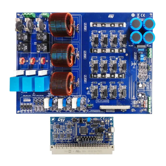
Page 2: Figure 2. Stdes-Pfcbidir Reference Design - Power Board
UM2979 Figure 2. STDES-PFCBIDIR reference design - power board Fully assembled board developed for performance evaluation only, not available for sale Figure 3. STDES-PFCBIDIR reference design - control board Fully assembled board developed for performance evaluation only, not available for sale The high switching frequency of the SiC MOSFETs (70 kHz) and the multilevel structure allow an efficiency of almost 99% as well as the optimization of passive power components in terms of size and cost. -
Page 3: Getting Started
During operation, do not touch the board as some of its components could reach a very high temperature. Block diagram Figure 4. STDES-PFCBIDIR block diagram Features • 3-phase, 3-level bidirectional AC-DC power converter: –... -
Page 4: Main Characteristics
Min. Typ. Max. Unit HVDC overvoltage protection DCovp HVCAP overvoltage protection CAPovp AC overcurrent protection ACovp Reference design description 1.5.1 Power board The figure below shows the power board of the STDES-PFCBIDIR reference design. UM2979 - Rev 1 page 4/70... -
Page 5: Figure 5. Stdes-Pfcbidir Reference Design - Power Board
UM2979 Reference design description Figure 5. STDES-PFCBIDIR reference design - power board The following figure shows the main sections of the power board. Figure 6. STDES-PFCBIDIR power board sections UM2979 - Rev 1 page 5/70... -
Page 6: Power Stage
UM2979 Reference design description 1.5.2 Power stage 1.5.2.1 Boost inductor Boost inductors are part of the LCL-R AC side filter. They allow obtaining the converter PFC operation by controlling the inductor current using a proper conduction pattern in the power device section. Continuous conduction mode (CCM) performs the PFC operation of this reference design. -
Page 7: Figure 9. Stdes-Pfcbidir Ntc Specifications
UM2979 Reference design description Figure 9. STDES-PFCBIDIR NTC specifications Figure 10. Active relays 1.5.2.3 Sensing 1.5.2.3.1 AC current An isolated sensor measures the AC input current. It represents the boost inductor current to be controlled for the proper operation of the PFC behavior of the power converter. -
Page 8: Figure 11. Ac Current Sensing Block Diagram
UM2979 Reference design description Figure 11. AC current sensing block diagram 1.5.2.3.2 AC voltage The three-phase AC voltages are obtained using a two-stage sensor circuit. The first part represents an isolated op-amp that allows measuring the HV through a voltage divider with an isolation barrier. Isol-Op-AMP output is limited in volts and is scaled with a second stage of op-amps with a proper gain and bias. -
Page 9: Figure 13. Dc Current Sensing Block Diagram
UM2979 Reference design description 1.5.2.3.3 DC current An isolated sensor measures the DC output current. Hall sensors are taken into consideration. A conditioning circuit allows obtaining the correct value for the ADCs. Figure 13. DC current sensing block diagram 1.5.2.3.4 DC voltage The DC voltages are obtained using two-stage sensing. -
Page 10: Control Board
1.5.3 Control board The figure below shows the control board of the STDES-PFCBIDIR reference design. Figure 15. STDES-PFCBIDIR reference design - control board The following figure shows the main sections of the control board. UM2979 - Rev 1 page 10/70... -
Page 11: Figure 16. Stdes-Pfcbidir Control Board Sections
UM2979 Reference design description Figure 16. STDES-PFCBIDIR control board sections Figure 17. STDES-PFCBIDIR MCU pin assignment UM2979 - Rev 1 page 11/70... -
Page 12: Power Factor Correction (Pfc) Benefits
UM2979 Power factor correction (PFC) benefits Power factor correction (PFC) benefits The figure below highlights the PFC benefits in terms of rest factor and power factor. Figure 18. PFC benefits Converter operation The figure below shows the current paths of the Vienna topology. To simplify the scheme, we considered the single phase representation. -
Page 13: How To Use The Stdes-Pfcbidir Reference Design
UM2979 How to use the STDES-PFCBIDIR reference design How to use the STDES-PFCBIDIR reference design System setup To use the STDES-PFCBIDIR, you need: • a programmable AC emulator or a programmable AC source; • a DC electronic load; • a power analyzer;... -
Page 14: Mcu Programming And Debugging
20- to 10-pin JTAG adapter to connect the platform to the PC. Figure 21. ST-LINK/V2 and adapter Figure 22. ST-LINK/V2 connected to the control board Step 2. Select the main.c file in the project/Application/User path. UM2979 - Rev 1... -
Page 15: Board Configuration
Click on the [Run] button to start the code execution. Figure 24. IAR EWARM debug procedure Board configuration STDES-PFCBIDIR is a customizable reference design. You can customize the power supply, the driving section, the grid relays, the inrush current limiter, and the DC current sensing technique. 2.4.1 Power supply section Two different input voltages are required for the power supply. -
Page 16: Driver Section
Open Open 2.4.3 Relay section STDES-PFCBIDIR allows managing the power in both directions (AC-DC rectifier mode a DC-AC inverter mode). To customize the AC side connection with the power converter, we considered four relays. Three of them are for the three-line connection and one is for the neutral. -
Page 17: Preliminary Test Procedure
UM2979 Preliminary test procedure Figure 27. Example of relay configuration Preliminary test procedure 2.5.1 AC sensing To verify the proper operation of the AC sensing, analyze some test points for voltages and currents as shown in the figures below. Figure 28. AC sensing section UM2979 - Rev 1 page 17/70... -
Page 18: Figure 29. Ac Voltage Sensing Test Procedure
UM2979 Preliminary test procedure Figure 29. AC voltage sensing test procedure Figure 30. AC grid voltage sensing test procedure UM2979 - Rev 1 page 18/70... -
Page 19: Dc Sensing
UM2979 Preliminary test procedure Figure 31. AC grid current sensing test procedure 2.5.2 DC sensing To verify the proper operation of the DC sensing, analyze the test points for voltages and currents as shown in the figures below. Figure 32. DC voltage sensing test procedure (1 of 2) UM2979 - Rev 1 page 19/70... -
Page 20: Ac Connection
DC voltage sensing test procedure (2 of 2) 2.5.3 AC connection Connect the STDES-PFCBIDIR AC main as shown below. A correct ABC sequence is mandatory for the proper operation of the power converter. Figure 34. AC main connection and sequence 2.5.4... -
Page 21: Relay Section
Figure 35. DC side load connection 2.5.5 Relay section STDES-PFCBIDIR reference design uses two groups of relays to manage the AC side connection and ICL. Step 1. To verify the functionality, configure the power board as shown below. Figure 36. -
Page 22: Controlled Startup Procedure
UM2979 Startup procedure Figure 37. Typical startup procedure 2.6.1 Controlled startup procedure The AC power supply is slowly increased to verify the procedure step-by-step as shown below. Figure 38. Connection and power-on procedure BLED “WAIT” START BLED Enable | Increase AC source Start “START”... -
Page 23: Figure 39. Stdes-Pfcbidir Relays
UM2979 Startup procedure Figure 39. STDES-PFCBIDIR relays The procedure consists of the following steps. FSM Wait: PWM signals are in IDLE state, configured in low state, to force all the MOSFETs in off state. The AC main voltage is already under monitoring. This state is maintained until AC main reaches a lower AC voltage threshold (OK_Plug_ACSource), that is 30 V . -
Page 24: Figure 41. Fsm_Idle Block Diagram
UM2979 Startup procedure FSM Idle: after TO_IDLE time elapses, wait for the AC mains to reach the uvAC value (OK_SOURCE). After checking the load current, a new timeout is set (TO_INIT) to prevent PLL instability. FSM moves to FSM_Init. All relays are maintained in the off state. Figure 41. -
Page 25: Direct Startup Procedure
UM2979 Startup procedure FSM_Start: is related to the burst mode operation of the power converter. During this procedure, the PWM is activated. The pulse sequence at a fixed duty cycle allows boosting the input voltage and increasing the DC output voltage at a reference voltage. The state machine then moves to FSM_Run state. Figure 43. -
Page 26: Control
UM2979 Control Control The voltage-oriented control allows controlling the PFC behavior of the converter in the dq-axis synchronous reference frame. Table 6. Control strategy comparison Reference frame Pros Cons • Poor in transient • Simple implementation with PI • Phase shifting (lag) •... -
Page 27: Figure 46. Continuous Conduction Mode In Current Control
UM2979 Control strategy Figure 46. Continuous conduction mode in current control Figure 47. Current decoupling control of the reference design converter model UM2979 - Rev 1 page 27/70... -
Page 28: Voltage Control Strategy
UM2979 Control strategy Figure 48. 3.1.2 Voltage control strategy The outer loop of the PFC operation is a voltage control. Figure 49. Converter DC side model The figure below shows the closed loop representation of the above model. UM2979 - Rev 1 page 28/70... -
Page 29: Phase Locked Loop
UM2979 Phase locked loop Figure 50. Voltage control diagram Phase locked loop In converter control, the PI regulators are usually used. This kind of regulator gets the best results when using a DC reference term. Figure 51. PLL internal regulator loop Figure 52. -
Page 30: Software Implementation
UM2979 Software implementation Software implementation STM32G474RET3 MCU controls the STDES-PFCBIDIR. The firmware package is based on the STM32Cube ecosystem. Starting from the STM32CubeMX, all the peripherals and pins used are activated and configured according to the basic project. The application firmware is supported and tested using STM32CubeIDE, IAR, and Keil development environments. -
Page 31: Figure 55. Ac-Dc Rectifier Application (A) And Dc-Ac Inverter Application Schematic Diagram (B)
STM32CubeProgrammer. At the end of this operation, the DPC application is tested and debugged through STM32CubeMonitor. The digital power converter firmware is then released, if compliant, and the DPC is adapted. STDES-PFCBIDIR reference design power converter allows managing the two-direction energy flow. The figure below shows the algorithm schematic diagram of the implementation in the AC-DC rectifier application and DC-AC inverter application. -
Page 32: Configuration Files
STDES-PFCBIDIR power converter configuration is based on two main configuration files. Figure 57. STDES-PFCBIDIR configuration files “DPC_application_conf.h” contains the application specific DEFINE (that is the ADC gain factor PI regulator gain, FSM configuration, control reference value, etc.). “DPC_Lib_conf.h” contains the configuration parameters linked to the MCU peripherals configuration. -
Page 33: Measurements
UM2979 Measurements Measurements PFC operation The figure below shows a steady state condition test considering 800 V DC voltage and 220 Vrms AC voltage with 15 kW DC load (constant current). This test represents the PFC operation with the DC voltage regulation active. Figure 58. -
Page 34: Uvp Ac
UM2979 UVP AC UVP AC Figure 60. UVP AC Power factor Figure 61. Power factor UM2979 - Rev 1 page 34/70... -
Page 35: Efficiency
UM2979 Efficiency Efficiency Figure 62. Efficiency The figure below shows the current THD measurements. Test conditions are V = 230 Vrms, V = 800 V. According to the specification, THD is lower than 5% starting from 10% of the full load. Figure 63. -
Page 36: Schematic Diagrams
Schematic diagrams Figure 64. STDES-PFCBIDIR schematic diagram - control board R128 VDD = 1.71 V to 3.6 V pag6 AN5093 IA+_uC VgridA.S_uC VgridA.S IinA U23A C137 VDD_3.3V AVDD_3.3V STM32G474RET3 WE-CBF VDD_3.3V_INT 2.2nF/50V 2.2nF/50V TP25 TestPoint TestPoint TestPoint TestPoint TestPoint 3JP_pcb... -
Page 37: Figure 65. Stdes-Pfcbidir Schematic Diagram - Power Board: Ac Current Sensing
Figure 65. STDES-PFCBIDIR schematic diagram - power board: AC current sensing VDD_5V 30Ohm@100MHz VDD_5V LEM1 LTSR 15-NP N.M. OinA_LEM OinA 100nF/16V 30Ohm@100MHz 1uF/25V 10k 0.1% 100nF/16V TestPoint_Ring 1uF/25V TestPoint_Ring TestPoint_Ring TestPoint_Ring OinA_LEM 4.12k 0.1% V_line_A_IN_LEM V_line_A N.M. TestPoint_Ring VDD_5V TSV912IDT TestPoint_Ring 10k 0.1%... -
Page 38: Figure 66. Stdes-Pfcbidir Schematic Diagram - Power Board: Ac Voltage Sensing
Figure 66. STDES-PFCBIDIR schematic diagram - power board: AC voltage sensing VDD_5V TP19 30Ohm@100MHz TestPoint_Ring TP20 VDD_5V ISOLATED DC/DC POWER SUPPLY 100nF/16V 1uF/25V VDD_5V TP21 TestPoint_Ring 27k 0,1% TestPoint_Ring V_conv_A 5V_MEAS_AC 30Ohm@100MHz VDD_BIAS_A 30Ohm@100MHz ZVD_A 36k 0.1% VDD_5V TP22 69.8k 0.1% N.M. -
Page 39: Figure 67. Stdes-Pfcbidir Schematic Diagram - Power Board: Aux Power Dc-Dc
Figure 67. STDES-PFCBIDIR schematic diagram - power board: aux power DC-DC Dev3 VDD_5V VDD_7V_INT VDD_3.3V LD29080S33R VDD_7V VOUT VDD_5V VOUT 30Ohm@100MHz 30Ohm@100MHz Rled1 VDD_7V_EXT C334 C335 Rled2 JP95 470nF/50V 10uF/50V Rled3 C337 C336 10uF/50V LD29080DT50R 470nF/50V C338 C339 Rled4 10uF/50V... -
Page 40: Figure 68. Stdes-Pfcbidir Schematic Diagram - Power Board: Aux Power Viper
Figure 68. STDES-PFCBIDIR schematic diagram - power board: aux power VIPER JP100 CENTRO_BUS DC_input Jp_pcb R347 51k/0.1% C346 3,3nF/200V R348 51k/0.1% Viper_Drain STTH1L06A R349 Aux_Viper C347 10/0.1% STPS1150A C348 15UF 450V 10uF/50V R350 G_BUS_N TP166 27k/0.1% TestPoint_Ring L19TBD VDD_12V_INT Viper_Drain... -
Page 41: Figure 70. Stdes-Pfcbidir Schematic Diagram - Power Board: Dc Current Sensing
Figure 70. STDES-PFCBIDIR schematic diagram - power board: DC current sensing VDD_5V 30Ohm@100MHz VDD_5V LEM4 R106 LTSR 15-NP N.M. TP52 30Ohm@100MHz R107 TP53 TP54 10k 0.1% 100nF/16V 100nF/16V 1uF/25V 1uF/25V TestPoint_Ring R108 U15A TestPoint_Ring TestPoint_Ring R109 TP55 Oout_LEM 3.4k 0.1%... -
Page 42: Figure 71. Stdes-Pfcbidir Schematic Diagram - Power Board: Dc Voltage Sensing
Figure 71. STDES-PFCBIDIR schematic diagram - power board: DC voltage sensing BUS_P 5V_MEAS_DC VDD_5V VDD_5V TP65 R124 TP66 30Ohm@100MHz 30Ohm@100MHz TestPoint_Ring 30Ohm@100MHz TestPoint_Ring R125 C100 GND_MEAS_DC C102 TP67 C101 100nF/16V 100nF/16V C103 C104 1uF/25V 4.7u/25V TP68 100nF/16V 1uF/25V R126 R127... -
Page 43: Figure 72. Stdes-Pfcbidir Schematic Diagram - Power Board: Gate Drivers (X12)
Figure 72. STDES-PFCBIDIR schematic diagram - power board: gate drivers (x12) JP11 TP79 Jp_pcb TestPoint_Ring VH_Q1_L 2STF1360 R150 R152 30Ohm@100MHz VDD_DRIVER 100nF/16V LED RED C127 JP15 C124 TP83 C125 C126 PWM_INP_Q1_L Jp_pcb 1uF/25V TP85 2.2uF/50V C136 C132 C137 VL_Q1_L VDD_DRIVER... -
Page 44: Figure 73. Stdes-Pfcbidir Schematic Diagram - Power Board: Grid Voltage Sensing
Figure 73. STDES-PFCBIDIR schematic diagram - power board: grid voltage sensing VDD_5V TP151 R294 27k 0,1% TestPoint_Ring V_grid_A U35D VDD_BIAS_grid_A R296 R295 VDD_5V TP152 R297 C301 TSV914IDT 5V_MEAS_AC 13.3k 0.1% N.M. C302 100nF/16V TestPoint_Ring R298 30Ohm@100MHz 30Ohm@100MHz C304 C303 VDD_BIAS_grid_A... -
Page 45: Figure 74. Stdes-Pfcbidir Schematic Diagram - Power Board: Power Section
Con2 CENTRO_BUS Con3_32A TP51 1-1393210-4 TestPoint_Ring Neutral COIL_RELAY_GRID_N STPS1L30A VDD_12V Figure 75. STDES-PFCBIDIR schematic diagram - power board: active inrush current and AC grid connection management VDD_12V VDD_12V VDD_12V R354 R355 R356 LED RED VDD_12V LED RED LED RED VDD_12V... -
Page 46: Figure 76. Stdes-Pfcbidir Schematic Diagram - Power Board: Temp Control
Figure 76. STDES-PFCBIDIR schematic diagram - power board: temp control VDD_12V R925.6k 100nF/16V Con2 GND1 LED RED 100nF/16V VDD_5V VOUT TP37 STLM20W87F TP38 TP39 5.1k TestPoint_Ring TP40 TestPoint_Ring TestPoint_Ring TEMP STS6NF20V TestPoint_Ring 100nF/16V... -
Page 47: Bill Of Materials
UM2979 Bill of materials Bill of materials Table 7. STDES-PFCBIDIR bill of materials Item Q.ty Ref. Part/value Description Manufacturer Order code Table 8. STDES-PFCBIDIR control Control board ST Not available for separate sale board Table 9. STDES-PFCBIDIR power Power board... - Page 48 UM2979 Bill of materials Item Q.ty Ref. Value Description Manufacturer Order code D3,D1 Uni-directional SMAJ5.0A-TR, SMA, 400 W SMAJ5.0A-TR TVS Diode, RED, SMD 0805, 2.4 V Red LED Wurth 150080RS75000 F1,F2, F3,F4, 22 Ohm@100 MHz, 6 A Ferrite beads Wurth 742792021 Solder jumper JP1,JP...
- Page 49 UM2979 Bill of materials Item Q.ty Ref. Value Description Manufacturer Order code R17,R 39,R45 ,R46,R Thick film SMD 50,R51 1 k, 603, 0.1 W, ±1% resistors ,R53,R 56,R13 1,R133 R23,R 30,R35 ,R126, Thick film SMD 0, 603, 0.1 W, ±1% R127, resistors R134,...
-
Page 50: Table 9. Stdes-Pfcbidir Power Board
UM2979 Bill of materials Table 9. STDES-PFCBIDIR power board Item Q.ty Ref. Part / Value Description Manufacturer Order code C1, C3, C7, C9, C13, C14, C83, C85, C91, C95, C99, C104, C108, C113, C117, C120, C124, C130, Multilayer ceramic C140, C181, 1µF, 25V, ±10%... - Page 51 UM2979 Bill of materials Item Q.ty Ref. Part / Value Description Manufacturer Order code C20, C24, C31, Multilayer ceramic C34, C38, C45, 1µF, 25V, ±10% capacitor SMD, C48, C52, C59, 0603 C61, C64 C21, C22, C32, C35, C36, C46, (not mounted), C49, C50, C60 N.M.
- Page 52 UM2979 Bill of materials Item Q.ty Ref. Part / Value Description Manufacturer Order code C205, C210, C216, C217, C221, C222, C225, C227, C228, C230, C231, C234, C235, C239, C244, C248, C253, C254, C259, C261, C264, C268, C274, C275, C278, C281, C283, C286, C287, C289, C292, C294,...
- Page 53 UM2979 Bill of materials Item Q.ty Ref. Part / Value Description Manufacturer Order code Electrolytic Panasonic C347 15µF, 450V Capacitor Through Electronic EEU-EE2W150 Hole Components Multilayer ceramic 10µF, 50V, C348 capacitor SMD, Murata ±10% 0805 Polypropylene Panasonic C349 560µF, 16V Capacitor through Electronic 16SEPF560M...
- Page 54 UM2979 Bill of materials Item Q.ty Ref. Part / Value Description Manufacturer Order code D10, D11, D12, D13, D15, D17, D18, D19, D34, Vishay D35, D36, D37, Zener Diode SMT 20V, 500mW Semiconductor TZMB20-GS08 D38, D39, D45, 2-Pin MiniMELF Diodes Division D47, D57, D59, D60, D61, D64, D65, D67, D73...
- Page 55 UM2979 Bill of materials Item Q.ty Ref. Part / Value Description Manufacturer Order code JP2, JP3, JP4, JP6, JP18, JP20, JP21, JP24, JP43, Solder jumper JP44, JP51, 3JP_pcb selector (not JP52, JP72, mounted) JP75, JP76, JP82 N.M (NOT Assembly) Fixed Terminal Phoenix Con2 Blocks GMKDS...
- Page 56 UM2979 Bill of materials Item Q.ty Ref. Part / Value Description Manufacturer Order code DIN 41612 Connectors 64P Digital Power 2.54MM VERT FML ERNI 284166 32X2 Connector TYPE B 4MM SLDR Phoenix Contact MKDS 5/3-9.5, 3 Phoenix J3, J4 Con3_32A 1714984 Way PCB Terminal Contact...
- Page 57 UM2979 Bill of materials Item Q.ty Ref. Part / Value Description Manufacturer Order code Q5, Q6, Q7, Silicon Carbide Q8, Q9, Q10, 650V, 45A HIP247 (not SCTW35N65G2V N.M (NOT mounted) Assembly) Q14, Q15, Q16, Q17, Q18, Q19, NPN Transistor, 3- 60V, 3A 2STF1360 Q20, Q21, Q22,...
- Page 58 UM2979 Bill of materials Item Q.ty Ref. Part / Value Description Manufacturer Order code R221, R232, R235, R236, R237, R238, R240, R255, R256, R266, R270, R271, R275, R276, R278, R281, R286, R288, R289 N.M (NOT Assembly) R2, R5, R6, R7, R10, R13, R14, R15, R18, R21, R22, R23,...
- Page 59 UM2979 Bill of materials Item Q.ty Ref. Part / Value Description Manufacturer Order code (not mounted), N.M. 0603 8.06k, 0.1W, Thin Film SMD R46, R68, R90 ±0.1% Resistor, 0603 (not mounted), R67, R89 N.M. 0603 470Ω, 0.1W, Thick Film SMD ±1% Resistor, 0603 Thick Film SMD...
- Page 60 UM2979 Bill of materials Item Q.ty Ref. Part / Value Description Manufacturer Order code R128, R133, Thick Film SMD 0, ±1% R142, R146 Resistor, 0603 R129, R134, 10.5k, 0.063W, Thin Film SMD R143, R147 ±0.1% Resistor, 0603 R130, R135, 1.6k, 0.063W, Metal Film SMD R141, R148 ±0.1%...
- Page 61 UM2979 Bill of materials Item Q.ty Ref. Part / Value Description Manufacturer Order code 750Ω, 0.25W, Thick Film SMD R345, R346 ±1% Resistor, 1206 51k, 0.25W, Thin Film SMD R347, R348 ±0.1% Resistor, 1206 10Ω, 0.1W, Thin Film SMD R349 ±0.1% Resistor, 0603 27k, 0.1W,...
- Page 62 UM2979 Bill of materials Item Q.ty Ref. Part / Value Description Manufacturer Order code TP82, TP83, TP84, TP85, TP86, TP87, TP88, TP89, TP90, TP91, TP92, TP93, TP94, TP95, TP96, TP97, TP98, TP99, TP100, TP101, TP102, TP103, TP104, TP105, TP106, TP107, TP108, TP109, TP110, TP111, TP112, TP113,...
- Page 63 UM2979 Bill of materials Item Q.ty Ref. Part / Value Description Manufacturer Order code U6, U9, U12, IC OPAMP Texas U17, U18, U20, ISOLATION 1 CIRC AMC1301DWVR Instruments U36, U38, U40 8SOIC, SOIC-8 1-Channel DC-DC Power Supply Texas U13, U22 Module 4-Pin, DCH010505SN7 Instruments...
-
Page 64: Revision History
UM2979 Revision history Table 10. Document revision history Date Revision Changes 28-Feb-2022 Initial release. UM2979 - Rev 1 page 64/70... -
Page 65: Table Of Contents
Converter operation ............12 How to use the STDES-PFCBIDIR reference design....... .13 System setup . - Page 66 UM2979 Contents Measurements..............33 PFC operation .
-
Page 67: List Of Tables
STDES-PFCBIDIR bill of materials ........ -
Page 68: List Of Figures
STDES-PFCBIDIR reference design - control board ........ - Page 69 STDES-PFCBIDIR schematic diagram - power board: connector ....... . 40...
- Page 70 ST’s terms and conditions of sale in place at the time of order acknowledgement. Purchasers are solely responsible for the choice, selection, and use of ST products and ST assumes no liability for application assistance or the design of Purchasers’...
Need help?
Do you have a question about the STDES-PFCBIDIR and is the answer not in the manual?
Questions and answers