Summary of Contents for ST ST92163
- Page 1 ST9 FAMILY ST92163 DEMO BOARD USER MANUAL Release 1.0 June 1999 DOC- ST92163 DEMO BOARD...
- Page 2 USE IN LIFE SUPPORT DEVICES OR SYSTEMS MUST BE EXPRESSLY AUTHORIZED. STMicroelectronics PRODUCTS ARE NOT AUTHORIZED FOR USE AS CRITICAL COMPONENTS IN LIFE SUPPORT DEVICES OR SYSTEMS WITHOUT THE EXPRESS WRITTEN APPROVAL OF STMicroelectronics. As used herein: 1. Life support devices or systems are those 2.
-
Page 3: Introduction
ST92E163. After setting some jumpers, as described in chapter 3, the user can plug the ST92163 Demo Board to the PC with the USB cable and dialogue with the ST Demo Board software via different HID transfers. -
Page 4: Table Of Contents
2.4 BILL OF MATERIALS ........10 3 ST92163 DEMO BOARD EXAMPLE ....... . 12 3.1 INTRODUCTION . - Page 5 – ST92163 Demo Board. – ST92E163 programmed with a HID transfer demonstration. – User manual (this document). – Floppy disk with the ST Demo Board software need to use the HID transfer demonstration. – ST92163 Datasheet. – ”ST9 8/16-BIT MCU FAMILY” CD ROM.
-
Page 6: St92163 Demo Board Characteristics
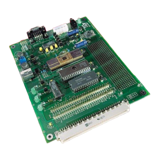
ST92163 DEMO BOARD CHARACTERISTICS 2 ST92163 DEMO BOARD CHARACTERISTICS This ST92163 Demo Board has been designed to offer to developer a wide range of possibil- ities for developing his specific application as fast as possible. The following chapters describe all the characteristics of the ST92163 Demo Board. -
Page 7: Features And Functions Description
JP8 to connect the ADC IN pin (P6.2) to the trimmer. 2.2.5 LEDS Three LEDs can be directly driven from microcontroller Port 6. They can be used to test the ST92163 I/Os. You only need to put jumpers on JP10, JP11 and JP12 to use the LEDs 5/17... -
Page 8: I/O Connector
ST92163 DEMO BOARD CHARACTERISTICS The following table shows the correspondence between the LEDs and the Port 6 pins. Table 3. Correspondence between LEDs and Port 6 pins Port 6 pin LED number P6.3 P6.4 P6.5 2.2.6 I/O CONNECTOR The two I/O connectors TP1 and TP2 allow you to probe or to connect all the microcontroller pins, the address latch outputs, the RS232 DB9 connector pins, VCC and GND. -
Page 9: I/O Expansion Connector
ST92163 DEMO BOARD CHARACTERISTICS 2.2.7 I/O EXPANSION CONNECTOR On the I/O expander (J3) it is possible to connect a daughter board to develop specific appli- cation. On this connector all the microcontroller’s pins are available but the developer will find too the address latch outputs (pin 45 to 52), the RS232 DB9 connector pins (pin 1 to 7 and pin 34), VCC (pin 31 and 32) and GND (pin 33). -
Page 10: External Memories
2.2.9 POWER SUPPLY CONNECTOR The ST92163 Demo Board can be powered either through a jack allowing the use of an ex- ternal AC/DC transformer or through the J2 connector allowing the power to be supplied from an internal PC 5”1/4 power supply connector. -
Page 11: St92163 Demo Board Schematic
ST92163 DEMO BOARD CHARACTERISTICS 2.3 ST92163 DEMO BOARD SCHEMATIC The following diagram shows the connection between the components of the ST92163 Demo Board . 9/17... -
Page 12: Bill Of Materials
ST92163 DEMO BOARD CHARACTERISTICS 2.4 BILL OF MATERIALS The following table describes all components installed on the ST92163 Demo Board. Table 6. Bill of Materials Reference Part Usage 100m (25V) 100n 100n 100m (25V) 1u pol 1u pol 1u pol... - Page 13 ST92163 DEMO BOARD CHARACTERISTICS Reference Part Usage LED GREEN 5mm LED I/O Driven Jack AC/DC transformer 5”1/4 power supply PC power supply DIN2X32DM-2R I/O expander CON1 USB connector (B) USB Upstream DB9 male RS232 Connector Jumper USB or external power supply Zener Diode 1.5K...
-
Page 14: St92163 Demo Board Example
3 ST92163 DEMO BOARD EXAMPLE 3.1 INTRODUCTION In this package, a user friendly example for the ST92163 Demo board is programmed in the ST92E163 microcontroller. This example uses the ST92163 Demo Board as an Human Inter- face Device (HID) that dialogues with the dedicated “ST Demo Board” PC software. -
Page 15: Installation
ST92163 DEMO BOARD EXAMPLE 3.2 INSTALLATION The first step is to install the “ST Demo Board” software in your PC by using the setup.exe command on the floppy disk provided with this package. After that, put jumpers on the following connectors: –... -
Page 16: Hid Transfer
Launch the “ST Demo Board” software. Plug the ST92163 Demo Board to the PC USB con- nector with the provided USB cable. If the ST92163 Demo Board is plugged in for the first time see the note in chapter 3.2. Afterthat, all the information concerning the device will be displayed in the “ST Demo Board”... - Page 17 This publication supersedes and replaces all information previously supplied. STMicroelectronics products are not authorized for use as critical components in life support devices or systems without the express written approval of STMicroelectronics. The ST logo is a registered trademark of STMicroelectronics ©1999 STMicroelectronics - All Rights Reserved.


Need help?
Do you have a question about the ST92163 and is the answer not in the manual?
Questions and answers