Sign In
Upload
Manuals
Brands
ST Manuals
Computer Hardware
STDES-PFCBIDIR
ST STDES-PFCBIDIR Power Converter Manuals
Manuals and User Guides for ST STDES-PFCBIDIR Power Converter. We have
1
ST STDES-PFCBIDIR Power Converter manual available for free PDF download: User Manual
ST STDES-PFCBIDIR User Manual (70 pages)
Brand:
ST
| Category:
Computer Hardware
| Size: 5 MB
Table of Contents
Figure 1. DC Charging Station
1
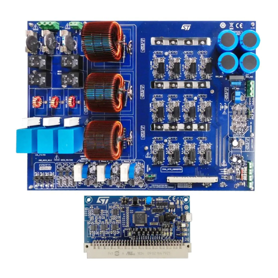
Figure 2. STDES-PFCBIDIR Reference Design - Power Board
2
Figure 3. STDES-PFCBIDIR Reference Design - Control Board
2
Getting Started
3
Safety Information
3
Block Diagram
3
Features
3
Figure 4. STDES-PFCBIDIR Block Diagram
3
Main Characteristics
4
Reference Design Description
4
Power Board
4
Table 1. Main Characteristics
4
Table 2. Protection Characteristics
4
Figure 5. STDES-PFCBIDIR Reference Design - Power Board
5
Figure 6. STDES-PFCBIDIR Power Board Sections
5
Power Stage
6
Table 3. Boost Inductor Parameters
6
Figure 7. Three and Four-Wire Connections
6
Figure 8. Passive NTC
6
Figure 9. STDES-PFCBIDIR NTC Specifications
7
Figure 10. Active Relays
7
Figure 11. AC Current Sensing Block Diagram
8
Figure 12. AC Voltage Sensing Block Diagram
8
Figure 13. DC Current Sensing Block Diagram
9
Control Board
10
Figure 14. DC Voltage Sensing Block Diagram
10
Figure 15. STDES-PFCBIDIR Reference Design - Control Board
10
Figure 16. STDES-PFCBIDIR Control Board Sections
11
Figure 17. STDES-PFCBIDIR MCU Pin Assignment
11
Power Factor Correction (PFC) Benefits
12
Converter Operation
12
Figure 18. PFC Benefits
12
Figure 19. Switching Paths of the Vienna Topology
12
How to Use the STDES-PFCBIDIR Reference Design
13
System Setup
13
How to Connect the Reference Design
13
Table 4. Operation Condition Limits
13
Figure 20. STDES-PFCBIDIR Connection
13
MCU Programming and Debugging
14
Figure 21. ST-LINK/V2 and Adapter
14
Figure 22. ST-LINK/V2 Connected to the Control Board
14
Board Configuration
15
Power Supply Section
15
Figure 23. IAR EWARM Program Procedure
15
Figure 24. IAR EWARM Debug Procedure
15
Driver Section
16
Relay Section
16
Table 5. Example of Driving Section Configuration
16
Figure 25. Example of Power Supply Configuration
16
Figure 26. Example of Driver Configuration
16
Preliminary Test Procedure
17
AC Sensing
17
Figure 27. Example of Relay Configuration
17
Figure 28. AC Sensing Section
17
Figure 29. AC Voltage Sensing Test Procedure
18
Figure 30. AC Grid Voltage Sensing Test Procedure
18
DC Sensing
19
Figure 31. AC Grid Current Sensing Test Procedure
19
Figure 32. DC Voltage Sensing Test Procedure (1 of 2)
19
AC Connection
20
DC Connection
20
Figure 33. DC Voltage Sensing Test Procedure (2 of 2)
20
Figure 34. AC Main Connection and Sequence
20
Relay Section
21
Startup Procedure
21
Figure 35. DC Side Load Connection
21
Figure 36. Relay Jumper Configuration
21
Controlled Startup Procedure
22
Figure 37. Typical Startup Procedure
22
Figure 38. Connection and Power-On Procedure
22
Figure 39. STDES-PFCBIDIR Relays
23
Figure 40. Fsm_Wait Block Diagram
23
Figure 41. Fsm_Idle Block Diagram
24
Figure 42. Fsm_Init Block Diagram
24
Direct Startup Procedure
25
Figure 43. Fsm_Start Block Diagram
25
Figure 44. Fsm_Run Block Diagram
25
Control
26
Control Strategy
26
Current Control Strategy
26
Table 6. Control Strategy Comparison
26
Figure 45. Cascaded Control
26
Figure 46. Continuous Conduction Mode in Current Control
27
Figure 47. Current Decoupling Control of the Reference Design Converter Model
27
Voltage Control Strategy
28
Figure 48. CDC
28
Figure 49. Converter DC Side Model
28
Phase Locked Loop
29
Figure 50. Voltage Control Diagram
29
Figure 51. PLL Internal Regulator Loop
29
Figure 52. PLL in AC Main Voltage
29
Software Implementation
30
Figure 53. Stm32Cube Ecosystem Development Flow
30
Figure 54. DPC Development Flow
30
Figure 55. AC-DC Rectifier Application (A) and DC-AC Inverter Application Schematic Diagram (B)
31
Configuration Files
32
Figure 56. Simplified Execution Task of the Control in AC-DC (A) and DC-AC (B)
32
Figure 57. STDES-PFCBIDIR Configuration Files
32
Measurements
33
PFC Operation
33
Step Load
33
Figure 58. PFC Operation
33
Figure 59. Step Load
33
Uvp Ac
34
Power Factor
34
Figure 60. UVP AC
34
Figure 61. Power Factor
34
Efficiency
35
Thd
35
Figure 62. Efficiency
35
Figure 63. THD
35
Schematic Diagrams
36
Figure 64. STDES-PFCBIDIR Schematic Diagram - Control Board
36
Figure 65. STDES-PFCBIDIR Schematic Diagram - Power Board: AC Current Sensing
37
Figure 66. STDES-PFCBIDIR Schematic Diagram - Power Board: AC Voltage Sensing
38
Figure 67. STDES-PFCBIDIR Schematic Diagram - Power Board: Aux Power DC-DC
39
Figure 68. STDES-PFCBIDIR Schematic Diagram - Power Board: Aux Power VIPER
40
Figure 69. STDES-PFCBIDIR Schematic Diagram - Power Board: Connector
40
Figure 70. STDES-PFCBIDIR Schematic Diagram - Power Board: DC Current Sensing
41
Figure 71. STDES-PFCBIDIR Schematic Diagram - Power Board: DC Voltage Sensing
42
Figure 72. STDES-PFCBIDIR Schematic Diagram - Power Board: Gate Drivers (X12)
43
Figure 73. STDES-PFCBIDIR Schematic Diagram - Power Board: Grid Voltage Sensing
44
Figure 74. STDES-PFCBIDIR Schematic Diagram - Power Board: Power Section
45
Figure 75. STDES-PFCBIDIR Schematic Diagram - Power Board: Active Inrush Current and AC Grid Connection Management
45
Figure 76. STDES-PFCBIDIR Schematic Diagram - Power Board: Temp Control
46
Bill of Materials
47
Table 7. STDES-PFCBIDIR Bill of Materials
47
Table 8. STDES-PFCBIDIR Control Board
47
Table 9. STDES-PFCBIDIR Power Board
50
Revision History
64
Table 10. Document Revision History
64
Table of Contents
65
List of Tables
67
List of Figures
68
Advertisement
Advertisement
Related Products
ST STDES-50W2CWBC
ST STDES-65ACFADP
ST STM32WB Series
ST STM32H745
ST STM32H747
ST STEVAL-TTM001V1
ST STEVAL-C34KAT1
ST STM32U5 Nucleo-64
ST STEVAL-ISQ008V1
ST STM32F078RBT6
ST Categories
Motherboard
Computer Hardware
Microcontrollers
Control Unit
Controller
More ST Manuals
Login
Sign In
OR
Sign in with Facebook
Sign in with Google
Upload manual
Upload from disk
Upload from URL