Table of Contents
Advertisement
Quick Links
UM2691
User manual
How to use the evaluation board for the ADC120 8-channel analog to digital
converter
Introduction
The
STEVAL-AKI001V1
evaluation board allows the user to evaluate the conversion performance of the
ADC120
8-channel
analog-to-digital converter designed for 50 ksps to 1 Msps conversion.
The board has several on-board sources like temperature sensor and strain gauge signals, and can accept external signals to
allow measurement and evaluation of the ADC120 conversion performance based on its successive approximation register
(SAR) with internal track-and-hold cell.
The board is supplied ready-to-use in standalone mode, or it can be plugged onto a
NUCLEO-L476RG
board with SMT32
microcontroller, which enables further signal processing and PC communication.
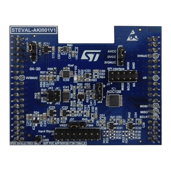
Figure 1.
STEVAL-AKI001V1 evaluation board for the ADC120
UM2691 - Rev 2 - September 2020
www.st.com
For further information contact your local STMicroelectronics sales office.
Advertisement
Table of Contents

Related Manuals for ST STEVAL-AKI001V1


Summary of Contents for ST STEVAL-AKI001V1
-
Page 1: Figure 1. Steval-Aki001V1 Evaluation Board For The Adc120
The board is supplied ready-to-use in standalone mode, or it can be plugged onto a NUCLEO-L476RG board with SMT32 microcontroller, which enables further signal processing and PC communication. Figure 1. STEVAL-AKI001V1 evaluation board for the ADC120 UM2691 - Rev 2 - September 2020 www.st.com For further information contact your local STMicroelectronics sales office. -
Page 2: Board Overview
Pin 16 (In7): input not directly connected, footprints are left to the user to allow amplification Figure 2. STEVAL-AKI001V1 block diagram The STEVAL-AKI001V1 evaluation board includes the following hardware functionality: • 2.54mm, 38cts double female connectors to be plugged to the STM32L476RG Nucleo development board (J1) •... - Page 3 UM2691 Board overview • J31 - VREF • J44 - GND UM2691 - Rev 2 page 3/27...
-
Page 4: Board Connection And Operation
UM2691 Board connection and operation Board connection and operation Power supply The power supply input can be selected form the following sources: • 5V from Nucleo board or external supply (if Nucleo is not used) • 3V3 voltage from Nucleo development board. JP4 enables the 3V3 LDO that converts the 5V into 3V3. -
Page 5: Board Operation
A code running inside a microcontroller can calculate the proper value in volts or in degrees Celsius, depending on the analog sensor used. RELATED LINKS Visit the ST website to download application note AN5454 UM2691 - Rev 2 page 5/27... -
Page 6: Steval-Aki001V1 Adc Inputs
The voltage V (V) image of the temperature T (°C) is given by the following equation: RELATED LINKS Visit the STLM20 product page on the ST website for more information regarding this device ADC channel 1: temperature measurement The input channel 1 on the ADC120 receives the voltage image of the PT100 resistor on the evaluation board. -
Page 7: Adc Channel 2: Input For Strain Gauge Measurement
ADC channel 2: input for strain gauge measurement The ADC120 input channel 2 measures and amplifies the strain gauge variation via a Wheatstone bridge. Figure 7. STEVAL-AKI001V1 schematic - instrumentation amplifier for strain gauge measurement Strain Gauge Set Strain_gauge_ref AVCC... -
Page 8: Adc Channel 4: Reference Voltage Measurement
J31 on the left (VREF) or on the right (In4), respectively. RELATED LINKS Visit the TS3431 product page on the ST website for more information regarding this device ADC channel 5: external 0-3V3 voltage measurement Pin 12 on connector J2 can be used to connect a 0 to 3V3 voltage to test the conversion of the ADC120 on a custom level voltage. -
Page 9: Adc Channel 6: User Configurable Gain Input
Pin 14 of connector J2 can be used to connect a voltage and configure the schematic as shown below to provide amplification, a divider, a filter, etc. Figure 11. STEVAL-AKI001V1 schematic - user configurable gain ADC channel 6 AVCC AVCC... -
Page 10: Schematic Diagrams
ADC120 V_REF ADC_4 DOUT ADC_5 ADC_6 NUCLEO - CN10 ADC_7 NUCLEO - CN10 SPI_SCLK SPI_MISO SPI_MOSI Figure 14. STEVAL-AKI001V1 schematic diagram - power supply 3V3 AVCC IC11 5V_NUCLEO LDK220M 3.3V_D Generate 1µF 1µF DVCC Generate ADJ/NC DVCC 3.3V_NUCLEO 1µF 0.1µF... -
Page 11: Figure 15. Steval-Aki001V1 Schematic Diagram - Reference Voltage
Figure 15. STEVAL-AKI001V1 schematic diagram - reference voltage AVCC AVCC 22nF AVCC V_REF V_REF 0.1µF 10µF IC23 0.1% 0.1% TSX711 10nF 1.8K 3.9K IC21 TS3431 ±5V input to 0-3V ADC V_REF AVCC C22 22nF SBR0220T5-7 ADC_3 IC22 TSX711 10nF 7.5K... -
Page 12: Figure 16. Steval-Aki001V1 Schematic Diagram - Adc Inputs
Figure 16. STEVAL-AKI001V1 schematic diagram - ADC inputs ADC inputs: strain gauge, 4, 5, 6, 7 AVCC AVCC V_REF SBR0220T5-7 ADC_4 Generate ADC_4 10nF AVCC SBR0220T5-7 ADC_5 10nF AVCC AVCC C32 22nF R31 NC SBR0220T5-7 ADC_6 IC31 TSX711 10nF C31 NC... -
Page 13: Figure 17. Steval-Aki001V1 Schematic Diagram - Instrumentation Amplifier For Strain Gauge
Figure 17. STEVAL-AKI001V1 schematic diagram - Instrumentation amplifier for strain gauge Strain Gauge Set Strain_gauge_ref AVCC C4122nF AVCC 0.1% V+_Wheatstone AVCC IC41A 0.1% TSZ122 FSG + 0.1% AVCC AVCC C4322nF EXTERNAL RESITOR 0.1% SBR0220T5-7 FSG - ADC_2 IC42 TSZ121 10nF 0.1%... -
Page 14: Figure 18. Steval-Aki001V1 Schematic Diagram - Temperature Measurement
Figure 18. STEVAL-AKI001V1 schematic diagram - temperature measurement AVCC C53 0.1µF AVCC AVCC IC51 STLM20 SBR0220T5-7 VOUT ADC_0 0.1µF Temperature measurement - STLM20 1.8K 1.8K AVCC C54 22nF V_REF 3.6K IC52A TSU112 AVCC AVCC Rref 3.6K 0.1µF 10µF C58 10nF 1.8K... -
Page 15: Bill Of Materials
UM2691 Bill of materials Bill of materials Table 1. STEVAL-AKI001V1 bill of materials Item Q.ty Ref. Part / Value Description Manufacturer Order code C2, C3, C24, C26, C35, C36, 10nF, SMT CAPACITOR - C37, C38, C44, 0603, 25V minV CERAMIC C57, C58, C59 1µF, SMT 0603,... - Page 16 UM2691 Bill of materials Item Q.ty Ref. Part / Value Description Manufacturer Order code OPERATIONAL AMPLIFIERS, IC53 SC 70-5, 5.5V TSU111ICT -55°C TO 130°C, TSU11X NUCLEO - CN10, SIP 19x2 CONNECTOR - - STEP HEADER, -55°C SAMTEC SSQ-119-03-G-D 2.54MM, TO 125°C, SSQ 655VDCV, 6.3A Input Signal, CONNECTOR -...
- Page 17 UM2691 Bill of materials Item Q.ty Ref. Part / Value Description Manufacturer Order code 0, SMT 0603, R37, R38 RESISTOR ±1% 120, SMT 0603, R43, R44, R45 RESISTOR ±0.1% 20K, SMT 0603, R47, R49 RESISTOR ±0.1% 1K, SMT 0603, RESISTOR ±0.1% R50, R51, R52, 33K, SMT 0603,...
-
Page 18: Board Layout
UM2691 Board layout Board layout Figure 19. STEVAL-AKI001V1 board dimensions Figure 20. STEVAL-AKI001V1 board top layer UM2691 - Rev 2 page 18/27... -
Page 19: Figure 21. Steval-Aki001V1 Board Bottom Layer
UM2691 Board layout Figure 21. STEVAL-AKI001V1 board bottom layer Figure 22. STEVAL-AKI001V1 board top silkscreen UM2691 - Rev 2 page 19/27... -
Page 20: Figure 23. Steval-Aki001V1 Board Bottom Silkscreen
UM2691 Board layout Figure 23. STEVAL-AKI001V1 board bottom silkscreen Figure 24. STEVAL-AKI001V1 board top solder UM2691 - Rev 2 page 20/27... -
Page 21: Figure 25. Steval-Aki001V1 Board Bottom Solder
UM2691 Board layout Figure 25. STEVAL-AKI001V1 board bottom solder Figure 26. STEVAL-AKI001V1 board top assembly UM2691 - Rev 2 page 21/27... -
Page 22: Figure 27. Steval-Aki001V1 Board Bottom Assembly
UM2691 Board layout Figure 27. STEVAL-AKI001V1 board bottom assembly UM2691 - Rev 2 page 22/27... -
Page 23: Revision History
UM2691 Revision history Table 2. Document revision history Date Version Changes 08-Apr-2020 Initial release. Updated Section 1 Board overview, Section 3.4 ADC channel 3: acquisition of a ±5 V signal on IN3 23-Sep-2020 Section 4 Schematic diagrams. UM2691 - Rev 2 page 23/27... -
Page 24: Table Of Contents
STEVAL-AKI001V1 ADC inputs ........ - Page 25 STEVAL-AKI001V1 schematic - reference voltage measurement ....... . . 8...
- Page 26 STEVAL-AKI001V1 bill of materials ........
- Page 27 ST’s terms and conditions of sale in place at the time of order acknowledgement. Purchasers are solely responsible for the choice, selection, and use of ST products and ST assumes no liability for application assistance or the design of Purchasers’...
Need help?
Do you have a question about the STEVAL-AKI001V1 and is the answer not in the manual?
Questions and answers