Table of Contents
Advertisement
Quick Links
Getting started with the STEVAL-QUADV01 evaluation board based on L6981,
L7983 and ST1PS03 DC-DC converter buck regulators, and ST730 LDO
Introduction
The
STEVAL-QUADV01
evaluation board features four different step-down regulators.
The board provides four different means of providing an output voltage of 5 V. The output voltages can be easily set to other
values by changing the resistors in resistive dividers of the feedback networks.
The evaluation board is based on the L6981, L7983, and
ST730
LDO, which offers various benefits for voltage conversion from multiple input levels.
The
L6981
synchronous monolithic step-down regulator is capable of delivering up to 1.5 A DC. Its wide input voltage range
makes the device suitable for a broad range of applications. The device implements peak current mode architecture in an SO 8L
package with internal compensation to minimize design complexity and size. The
(LCM) and low noise mode (LNM) versions. LCM maximizes efficiency at light load with controlled output voltage ripple, making
the device extremely suitable for battery-powered applications. LNM makes the switching frequency constant and minimizes the
output voltage ripple overload current range, meeting the specifications for noise sensitive applications. The EN pin manages
the enable/disable function. The typical shutdown current is 2 μA when disabled. When the EN pin is pulled up, the device
is enabled and the internal 1.3 ms soft-start takes place. Pulse-by-pulse current sensing on both power elements implements
effective constant current protection while thermal shutdown prevents thermal run-away.
The
L7983
regulator is a step-down monolithic switching regulator that can deliver up to 300 mA DC, based on peak current
mode architecture. The wide input voltage range and adjustable UVLO threshold meet the specification for 12 V, 24 V, and 48
V industrial bus standards. The selected switching frequency is 1 MHz. It can be adjusted by applying an external clock on
the LNM/LCM pin or by changing the frequency programming resistor.
to low noise mode (LNM) transition. LCM is designed for applications with active idle mode to maximize the efficiency at light
load with controlled output voltage ripple, while LNM keeps the switching frequency constant over the load current range for
low noise applications. The soft start time is internally fixed and the output voltage supervisor manages the reset phase for any
digital load (MCU, FPGA, etc.). The internal compensation network features high noise immunity, simple design, and component
cost savings. The RST open collector output can also implement output voltage sequencing during the power-up phase. The
synchronous rectification, designed for high efficiency at medium to heavy loads, and the high switching frequency capability
contribute to size reduction in final application designs. Pulse-by-pulse current sensing on both power elements implements
effective constant current protection.
The
ST1PS03
is a step-down converter able to deliver up to 400 mA output current from a 1.8 to 5.5 V input, with a 1.6 to
3.3 V dynamically adjustable output voltage. The board features the ST1PS03AQTR nano-quiescent miniaturized synchronous
step-down converter, which implements enhanced peak current control (PCC) and advanced design circuitry to minimize
quiescent current. The device embeds a controlled load switch to supply a subsystem with VIN_AUX voltage rail. The design
demonstrates how high efficient conversion can be achieved thanks to the ST1PS03AQTR (in a thin TQFN12 package of
2.0x1.7 mm), a 2.2 μH inductor, and two small capacitors.
The
ST730
is a low-quiescence medium input voltage (28 V) LDO able to deliver up to 300 mA output current from a 2.5 V to 28
V input. Thanks to its low quiescence, it is suitable in always-on applications. The
clamps the output current to a safe value in case of overload or short-circuit.
All regulators feature thermal protections that disable the device in case it reaches critical temperatures that might damage the
devices.
You can use the
eDesignSuite
converters before verifying the simulation results on the evaluation board.
UM3114 - Rev 1 - April 2023
For further information contact your local STMicroelectronics sales office.
ST1PS03
and
eDSim
software tools to simulate and configure the L6981, L7983, and
synchronous step-down converters. It also features the
L6981
is available in low consumption mode
L7983
supports dynamic low consumption mode (LCM)
ST730
features an SOA-type protection that
UM3114
User manual
ST1PS03
buck
www.st.com
Advertisement
Table of Contents

Related Manuals for ST STEVAL-QUADV01


Summary of Contents for ST STEVAL-QUADV01
- Page 1 UM3114 User manual Getting started with the STEVAL-QUADV01 evaluation board based on L6981, L7983 and ST1PS03 DC-DC converter buck regulators, and ST730 LDO Introduction STEVAL-QUADV01 evaluation board features four different step-down regulators. The board provides four different means of providing an output voltage of 5 V. The output voltages can be easily set to other values by changing the resistors in resistive dividers of the feedback networks.
-
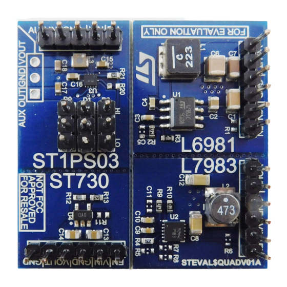
Page 2: Figure 1. Steval-Quadv01 Evaluation Board (Top View)
UM3114 Figure 1. STEVAL-QUADV01 evaluation board (top view) UM3114 - Rev 1 page 2/19... -
Page 3: Getting Started
UM3114 Getting started Getting started Safety instructions Caution: This board has to be used only by skilled technical personnel who are suitably qualified and familiar with the installation, use, and maintenance of power electronic systems. The same personnel must be aware of and must apply national accident prevention rules. - Page 4 UM3114 Features • ST730 – Wide input voltage range of 2.5 V to 28 V – Ultra-low quiescent current: typ. 5 μA at no-load, 10 μA max. across full temperature range, 1 μA max. in shutdown – High output voltage accuracy: ± 0.5% @ 25 °C, ± 2.5% across temperature range –...
-
Page 5: How To Use The Board
UM3114 How to use the board How to use the board All four regulators on the STEVAL-QUADV01 feature an adjustable V . Each circuit output voltage can be set freely by adjusting the resistor values. To use the board, follow the procedure below. -
Page 6: Connectors And Test Points
UM3114 Connectors and test points Connectors and test points Each regulator has a unique V connector. To use it, connect a supply voltage within the voltage range of the regulator to be used. should be connected to the power source with a short wire to avoid oscillations between the cable parasitic inductance and the input ceramic capacitor. -
Page 7: Edesignsuite And Edsim Sw Design Tools
ST products for power conversion applications. You can use them to customize the regulators for specific applications. Start by entering the main specifications for your design. Then, generate an automatic design or follow a sequential process to build a highly customized design. -
Page 8: Pcb Layout
UM3114 PCB layout PCB layout STEVAL-QUADV01 is a two-layer PCB with 1-oz copper thickness. Figure 4. STEVAL-QUADV01 PCB layout (1 of 2) Figure 5. STEVAL-QUADV01 PCB layout (2 of 2) UM3114 - Rev 1 page 8/19... -
Page 9: Bill Of Materials
UM3114 Bill of materials Bill of materials Table 1. STEVAL-QUADV01 bill of materials Item Q.ty Ref. Value Description Manufacturer Order code 10uF, 1206, 50 Input capacitor C3216X7R1H106K160AC 1uF, 0805, 50 V Input capacitor CGA4J3X7R1H105K125AB 1uF, 0603, 10 V VCC capacitor... - Page 10 UM3114 Bill of materials Item Q.ty Ref. Value Description Manufacturer Order code 60 V 300 mA synchronous L7983, DFN step-down 3X3X0.8 10L switching L7983PUR PITCH 0.5 regulator with 10 µA quiescent current 6x1, through Male SIL hole, 2.54mm Harwin M20-9990645 connector pitch, HDR1X6 Input, Output...
-
Page 11: Schematic Diagrams
Schematic diagrams Figure 6. STEVAL-QUADV01 circuit schematic (1 of 4) BOOT Enable Enable 100nF EN/CLK 10uF Vout Vout 22uH Header 6 402k AGND FB/VOUT L6981CDR 82.5k Figure 7. STEVAL-QUADV01 circuit schematic (2 of 4) Vin79 !RST En79 Vin79 En79 Vout_L79... -
Page 12: Figure 8. Steval-Quadv01 Circuit Schematic (3 Of 4)
Figure 8. STEVAL-QUADV01 circuit schematic (3 of 4) EnPS03 VinPS03 VinPS03 VinAux VIN_AUX VinAux VoutPS03 EnPS03 Header 5 VoutPS03 Inductor AuxIn VoutAux 2.2uH Header 3 VinPS03 VOUT Header 3 VoutAux VOUT_AUX VinPS03 ST1PS03AQTR Header 3 VinPS03 Header 3 Figure 9. -
Page 13: Regulatory Compliance
UM3114 Regulatory compliance Regulatory compliance Notice for US Federal Communication Commission (FCC) For evaluation only; not FCC approved for resale FCC NOTICE - This kit is designed to allow: (1) Product developers to evaluate electronic components, circuitry, or software associated with the kit to determine whether to incorporate such items in a finished product and (2) Software developers to write software applications for use with the end product. -
Page 14: Board Versions
STEVAL-QUADV01 versions PCB version Schematic diagrams Bill of materials STEVAL$QUADV01A STEVAL$QUADV01A schematic diagrams STEVAL$QUADV01A bill of materials 1. This code identifies the STEVAL-QUADV01 evaluation board first version. It is printed on the board PCB. UM3114 - Rev 1 page 14/19... -
Page 15: Revision History
UM3114 Revision history Table 3. Document revision history Date Revision Changes 26-Apr-2023 Initial release. UM3114 - Rev 1 page 15/19... -
Page 16: Table Of Contents
UM3114 Contents Contents Getting started ..............3 Safety instructions. -
Page 17: List Of Tables
STEVAL-QUADV01 bill of materials ........ -
Page 18: List Of Figures
STEVAL-QUADV01 evaluation board (top view) ........ - Page 19 ST’s terms and conditions of sale in place at the time of order acknowledgment. Purchasers are solely responsible for the choice, selection, and use of ST products and ST assumes no liability for application assistance or the design of purchasers’...
Need help?
Do you have a question about the STEVAL-QUADV01 and is the answer not in the manual?
Questions and answers