
Related Manuals for Stryker Trio 1033


Summary of Contents for Stryker Trio 1033
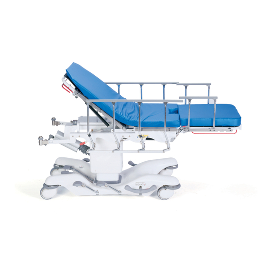
- Page 1 Trio Mobile ® Surgery Platform Model 1033 Maintenance Manual For Parts or Technical Assistance: USA: 1-800-327-0770 (option 2) 2007/08 1033-090-002 REV H www.stryker.com...
-
Page 3: Table Of Contents
Outer Box Assembly..............60 www.stryker.com... - Page 4 International Warranty Clause ............. 97 1033-090-002 REV H www.stryker.com...
-
Page 5: Introduction
Introduction InTenDeD uSe This manual is designed to assist you with the operation of Stryker Model 1033 Trio Mobile Surgery Platform. Carefully ® read this manual thoroughly before using the equipment or beginning maintenance on it. To ensure safe operation of this equipment, it is recommended that methods and procedures be established for educating and training staff on the safe operation of this stretcher. -
Page 6: Symbols
Symbols Warning, Refer to Service/Maintenance Manual Safe Working Load Symbol Return To Table of Contents 1033-090-002 REV H www.stryker.com... -
Page 7: Safety Tips And Guidelines
To ensure proper security for the patient, after attaching the siderail, be sure to slide it all the way to the end of the accessory rail until it hits the stop and won’t go any farther. Return To Table of Contents www.stryker.com 1033-090-002 REV H... - Page 8 Do not use the clamp-on siderails as push/pull devices or damage to the rails could occur. • The hood may not be used for stepping. note The bottom of the brake rings should be cleaned regularly to prevent wax and/or floor remmant buildup. Return To Table of Contents 1033-090-002 REV H www.stryker.com...
-
Page 9: Preventative Maintenance
Lubricate as required (see Service Information for Lubrification Points). ______ Tighten surgery accessory rails on Fowler and seat section. ______ Accessories and mounting hardware in good condition and working properly. Stretcher Serial Number: Completed by: _______________________________________ Date: _________________ Return To Table of Contents www.stryker.com 1033-090-002 REV H... -
Page 10: Cleaning
SoMe CleanIng ProDuCTS are CorroSIve In naTure anD May CauSe DaMage To The ProDuCT If uSeD IMProPerly. If the products suggested above are used to clean Stryker patient care equipment, measures must be taken to insure the stretcher is wiped with a damp cloth soaked in clean water and thoroughly dried following cleaning. -
Page 11: Service Information
1/8” Allen Wrench Procedure: Using a 1/8” Allen wrench, remove the screw and washer holding the caster cover to the wheel assembly. Reuse the screw and washer to install the new caster cover. Return To Table of Contents www.stryker.com 1033-090-002 REV H... -
Page 12: Base Hood Removal
The hydraulic fluid should be visible at the bottom of the fill hole. If it is not, add Mobil Aero HFA hydraulic fluid (Stryker part number 2020-070-475) until the fluid is visible at the bottom of the fill hole. Replace the fill plug. -
Page 13: Jack Assembly Removal And Replacement
Turn the blue knob clockwise to increase the litter descent rate. Turn it counterclockwise to decrease the litter descent rate. Adjust the valve so that the jack at the foot end of the stretcher will descend slightly faster than the jack at the head end. Return To Table of Contents www.stryker.com 1033-090-002 REV H... -
Page 14: Adjustable Pressure Compensated (P.c.) Valve Replacement
Using a 5/32” Allen wrench and a 7/16” wrench, remove the bolts and nuts holding the pneumatic cylinder(s) to the fifth wheel assembly and remove the cylinder(s). Reuse the bolts and nuts to install the new pneumatic cylinder(s). Replace the base hood. Return To Table of Contents 1033-090-002 REV H www.stryker.com... -
Page 15: Litter Removal
Using needle nose pliers, remove the rue ring from the left or right side of the outer box assembly and pull out the trend pivot shaft. Lift the lateral tilt assembly off the base assembly. Reverse the above procedure for reassembly. Return To Table of Contents www.stryker.com 1033-090-002 REV H... -
Page 16: Outer Box Assembly Removal
Remove the outer box assembly (see procedure above) Remove the T27 Torx head screw holding the lift gear on the gear shaft. Reverse the above steps to install the new gear. Return To Table of Contents 1033-090-002 REV H www.stryker.com... -
Page 17: Siderail Tension Adjustment
Remove the foot section from the unit and turn it over. Using a 3/32” hex Allen wrench, loosen the Allen screw on the red release handle. Move the handle until the desired locking force is achieved. Tighten the Allen screw. Return To Table of Contents www.stryker.com 1033-090-002 REV H... -
Page 18: Lubrication Points
Service Information luBrICaTIon PoInTS See Detail B See Detail A DETAIL A DETAIL B Return To Table of Contents 1033-090-002 REV H www.stryker.com... -
Page 19: Quick Reference Replacement Parts List
The parts and accessories listed on this page are all currently available for purchase. Some of the parts identified on the assembly drawing parts in this manual may not be individually available for purchase. Please call Stryker Customer Service USA: 1-800-327-0770 (Option 2), Canada: 1-888-233-6888 for availability and pricing. - Page 20 Return To Table of Contents Return To Table of Contents 1033-090-002 REV H 1033-090-002 REV H www.stryker.com www.stryker.com...
-
Page 21: Assembly Drawings
Common Components For Reference Only: Part Number 1033–026–010 Return To Table of Contents www.stryker.com 1033-090-002 REV H... - Page 22 Common Components Return To Table of Contents 1033-090-002 REV H www.stryker.com...
- Page 23 Common Components Return To Table of Contents www.stryker.com 1033-090-002 REV H...
- Page 24 Common Components Return To Table of Contents 1033-090-002 REV H www.stryker.com...
- Page 25 Common Components SURGERY ACCESSORY RAIL AND FOWLER ROLLER CHANNEL (TYPICAL BOTH SIDES) Return To Table of Contents www.stryker.com 1033-090-002 REV H...
- Page 26 Common Components Return To Table of Contents 1033-090-002 REV H www.stryker.com...
- Page 27 Common Components SIDERAIL ASSEMBLY (TYPICAL BOTH SIDES) Return To Table of Contents www.stryker.com 1033-090-002 REV H...
- Page 28 004-073-000 But. Hd. Cap Screw 1033-031-029 Fowler Roller Rub Strip 1033-032-440 Shaft Pivot Bracket BB 1033-031-031 Fowler Roller Channel 0026-334-000 Clevis Pin 0027-020-000 Rue Ring Cotter 0004-484-000 But. Hd. Cap Screw Return To Table of Contents 1033-090-002 REV H www.stryker.com...
-
Page 29: Base Assembly
Base assembly For Reference Only: Part Number 1033-1-10 BRAKE RING ASSEMBLY (TYPICAL 4 PLACES) Return To Table of Contents www.stryker.com 1033-090-002 REV H... - Page 30 Base assembly CASTER ASSEMBLY (TYPICAL 4 PLACES) Return To Table of Contents 1033-090-002 REV H www.stryker.com...
- Page 31 Base assembly Return To Table of Contents www.stryker.com 1033-090-002 REV H...
- Page 32 Base assembly Return To Table of Contents 1033-090-002 REV H www.stryker.com...
- Page 33 Base assembly Return To Table of Contents www.stryker.com 1033-090-002 REV H...
- Page 34 Base assembly Return To Table of Contents 1033-090-002 REV H www.stryker.com...
- Page 35 Base assembly Return To Table of Contents www.stryker.com 1033-090-002 REV H...
- Page 36 Base assembly BRAKE LINKAGE ASSEMBLY (TYPICAL BOTH SIDES) Return To Table of Contents 1033-090-002 REV H www.stryker.com...
- Page 37 Base assembly SECTION A−A Return To Table of Contents www.stryker.com 1033-090-002 REV H...
- Page 38 Jack Pump Coupler 0011-310-000 Flat Washer 1033-001-028 Brake Ring Link 0015-037-000 Hex Jam Nut AZ 1033-001-029 Brake Spring, Right 0016-014-000 Dynalock Nut BA 1033-001-030 Brake Spring, Left 0016-060-000 Torque Lock Nut Return To Table of Contents 1033-090-002 REV H www.stryker.com...
- Page 39 EA 1033-090-029 Pump Pedal Label, Lt. 0025-099-000 Blind Rivet EB 1033-090-030 Descent Pedal Label, Lt. 0004-491-000 Soc. Hd. Cap Screw EC 0946-201-060 Stryker Logo Label 0003-041-000 Hex Hd. Cap Screw ED 0004-142-000 Hex Soc. Hd. Screw 1033-001-306 Washer EE 0014-021-000 Washer...
-
Page 40: Base Pan Assembly - 1033-001-65
Base Pan assembly - 1033-001-65 Item Part no. Part name Qty. 0025-133-000 Blind Rivet 1033-001-066 Base Pan 1033-001-067 Base Pan Filler Plate 1033-001-068 Base Pan Felt Pad 0044-039-000 2” x 6” Acrylic Tape Return To Table of Contents 1033-090-002 REV H www.stryker.com... -
Page 41: Pedestal Lift Jack Assembly
Pedestal lift jack assembly For Reference Only: Part Number 1033–001–050 Pedestal Lift Jack Base see page 43 Return To Table of Contents www.stryker.com 1033-090-002 REV H... - Page 42 Pedestal lift jack assembly Return To Table of Contents 1033-090-002 REV H www.stryker.com...
- Page 43 0045-966-000 O-Ring 0921-001-252 Serial Number Label 0045-967-000 O-Ring 1033-001-051 Jack Assembly Label 0715-001-321 Check Valve Screen AA 1033-001-015 Jack Spacer Block 2025-700-026 Relief Valve Assembly AB 1033-001-027 Jack Pump Supt Arm. Return To Table of Contents www.stryker.com 1033-090-002 REV H...
-
Page 44: Pedestal Lift Jack Pump Assembly - 1033-001-070
Seal 0048-175-000 45° Straight Thread Elbow 1033-001-071 Pump Body 1033-001-072 Pump Brass End Cap 1033-001-073 Pump Shaft 1033-001-074 Pump Shaft Clevis 0026-318-000 Dowel Pin 1033-001-080 Pump Cylinder Spring 1033-001-090 Spring Seat Return To Table of Contents 1033-090-002 REV H www.stryker.com... -
Page 45: Wheel Assembly - 1033-001-225
Wheel assembly - 1033-001-225 Item Part no. Part name Qty. 0715-001-255 Wheel Bushing 6060-002-046 Bearing Spacer 1033-001-231 Molded Wheel 0081-226-000 Bearing Return To Table of Contents www.stryker.com 1033-090-002 REV H Back to Table of Contents... -
Page 46: Fowler Assembly
For Reference Only: Part Number 1033–031–010 Return To Table of Contents 1033-090-002 REV H www.stryker.com... - Page 47 Return To Table of Contents www.stryker.com 1033-090-002 REV H...
- Page 48 Fowler Tube Plug 0025-133-000 Blind Rivet 1033-031-111 Fowler Tube 0007-042-000 Truss Hd. Mach. Screw 1033-031-012 Fowler Roller Brkt., Rt. 0008-056-000 Soc. Hd. Should. Screw 1033-031-013 Fowler Roller Brkt., Lt. 0015-066-000 Hex Jam Nut Return To Table of Contents 1033-090-002 REV H www.stryker.com...
-
Page 49: Foot Section Receptacle, Right/Left - 1033-32-110/115
Qty. 0004-360-000 Button Hd. Cap Screw 0026-299-000 Clevis Pin 0016-122-000 Nylock Nut 1033-032-088 Foot Receptacle Plate, Left 1033-032-089 Foot Receptacle Plate, Right 1033-032-090 Foot Section Insert Guide 0027-025-000 Rue Ring Cotter Return To Table of Contents www.stryker.com 1033-090-002 REV H... -
Page 50: Foot/Fowler Receptacle, Right/Left
Rue Ring Cotter 0027-025-000 Rue Ring Cotter 1033-032-090 Guide Insert 1033-032-090 Guide Insert 1033-032-480 Receptacle, Right 1033-032-485 Receptacle, Left 1033-032-489 Outside Plate 1033-032-489 Outside Plate 0027-020-000 Rue Ring Cotter 0027-020-000 Rue Ring Cotter Return To Table of Contents 1033-090-002 REV H www.stryker.com... -
Page 51: Foot Assembly
For Reference Only: Part Number 1033–032–050 SIDERAIL & SURGERY ACCESSORY RAIL ASSEMBLY (TYPICAL BOTH SIDES) Return To Table of Contents www.stryker.com 1033-090-002 REV H... - Page 52 FOOT RELEASE HANDLE ASSEMBLY (TYPICAL BOTH SIDES) Return To Table of Contents 1033-090-002 REV H www.stryker.com...
- Page 53 Ft. Siderail Spring Brkt., Lt. 1033-032-012 Ft. Siderail Latch Spring 1033-090-034 Label, “Do Not Sit”, Domestic 1061-600-040 Label, “Do Not Sit”, International 0052-316-000 Nyliner 1001-226-019 Rubber Stop 0004-558-000 Soc. Hd. Cap Screw Return To Table of Contents www.stryker.com 1033-090-002 REV H...
-
Page 54: Foot End Siderail Assembly, Right - 1033-032-100
Spindle Top Plug Ass’y 1033-032-099 Siderail Latch Cover 1033-020-017 Top Bar End Cap Ass’y 0014-003-000 Washer 1033-032-011 Barrel Pivot Nut 0025-061-000 Semi-Tubular Rivet 1033-032-069 Top Rail Cap 1033-032-013 Barrel Nut 1033-032-072 Siderail Top Bar Return To Table of Contents 1033-090-002 REV H www.stryker.com... -
Page 55: Foot End Siderail Assembly, Left - 1033-032-105
Spindle Top Plug Ass’y 1033-032-099 Siderail Latch Cover 1033-020-017 Top Bar End Cap Ass’y 0014-003-000 Washer 1033-032-011 Barrel Pivot Nut 0025-061-000 Semi-Tubular Rivet 1033-032-069 Top Rail Cap 1033-032-013 Barrel Nut 1033-032-072 Siderail Top Bar Return To Table of Contents www.stryker.com 1033-090-002 REV H... -
Page 56: Siderail Assembly, Right - 1033-020-200
Siderail assembly, right - 1033-020-200 Return To Table of Contents 1033-090-002 REV H www.stryker.com... - Page 57 Siderail Top Bar End Cap 1033-020-030 Siderail Top Bar Weldment 1033-020-238 Siderail Timing Link 1033-020-210 Spindle Weldment, Right 1033-020-220 Latch Pivot Block 1033-020-230 Siderail Pivot Block 0014-079-000 Nylon Washer 0025-061-000 Semi-Tubular Rivet Return To Table of Contents www.stryker.com 1033-090-002 REV H...
-
Page 58: Siderail Assembly, Left - 1033-020-205
Siderail assembly, left - 1033-020-205 Return To Table of Contents 1033-090-002 REV H www.stryker.com... - Page 59 Siderail Top Bar End Cap 1033-020-030 Siderail Top Bar Weldment 1033-020-238 Siderail Timing Link 1033-020-215 Spindle Weldment, Left 1033-020-220 Latch Pivot Block 1033-020-230 Siderail Pivot Block 0014-079-000 Nylon Washer 0025-061-000 Semi-Tubular Rivet Return To Table of Contents www.stryker.com 1033-090-002 REV H...
-
Page 60: Outer Box Assembly
Box assembly For Reference Only: Part Number 1033–034–001 Return To Table of Contents 1033-090-002 REV H www.stryker.com... - Page 61 Outer Box Lower Trend Pivot 1033-034-061 Outer Box Foot Box 1033-034-062 Outer Box Head Box 1033-034-070 Outer Box Trend Pivot Cap, Rt. 1033-034-075 Outer Box Trend Pivot Cap, Lt. 0016-122-000 Nylock Nut Return To Table of Contents www.stryker.com 1033-090-002 REV H...
- Page 62 Trend actuator assembly - 1033-033-130 Return To Table of Contents 1033-090-002 REV H www.stryker.com...
-
Page 63: Trend Actuator Assembly - 1033-033-130
Trend Crank Handle 0081-316-000 Radial Bearing 1033-033-135 Trend Inner Screw Ass’y 1033-033-036 Trend Driver Spur Gear 1033-033-035 Crank Bellows 1033-033-037 Trend Driver Spur Gear 0081-226-000 Bearing 1033-033-042 Trend Housing 1033-033-033 Trend Glide Bearing Return To Table of Contents www.stryker.com 1033-090-002 REV H... -
Page 64: Trend Inner Screw Assembly - 1033-033-135
Trend Inner Screw assembly - 1033-033-135 Item Part no. Part name Qty. 0026-143-000 Spring Pin 1033-033-032 Trend Screw 1033-033-034 Trend Screw Pivot Return To Table of Contents 1033-090-002 REV H www.stryker.com... -
Page 65: Lateral Tilt Assembly
Tilt assembly For Reference Only: Part Number 1033–033–001 Return To Table of Contents www.stryker.com 1033-090-002 REV H... - Page 66 Trend Pivot Shaft 1033-034-111 Lateral Tilt Foot Pillow Block 1033-034-112 Lateral Tilt Head Pillow Block 1033-034-113 Lateral Tilt Pivot Spacer 1033-034-114 Lat. Tilt Brg. Adjustment Spacer 0004-456-000 But. Hd. Cap Screw Return To Table of Contents 1033-090-002 REV H www.stryker.com...
-
Page 67: Lateral Tilt Hinged Gear Assembly
Part name Qty. 0026-118-000 Spring Pin 0052-826-000 Hinged Gear Joint 1033-033-019 Acme Screw Hinge Gear Coupler 1033-033-016 Crank Shaft Hinge Gear Coupler 1033-033-029 Lateral Tilt Crank Shaft 1033-033-028 Hinge Gear Cover Return To Table of Contents www.stryker.com 1033-090-002 REV H... -
Page 68: Optional I.v. Pole Receptacles - 1033-110-030
I.v. Pole receptacles - 1033-110-030 Item Part no. Part name Qty. 0028-187-000 Spiral Retaining Ring 1033-030-038 Barrel Nut 1033-030-040 I.V. Pole Receptacle 1033-030-050 Bumper Roller 0007-058-000 Phillips Truss Hd. Screw Return To Table of Contents 1033-090-002 REV H www.stryker.com... -
Page 69: Removable I.v. Pole Assembly - 0721-047-006
I.v. Pole assembly - 0721-047-006 Item Part no. Part name Qty. 0938-001-305 Pole Socket Assembly 0938-001-308 Pole Assembly 0004-495-000 Soc. Hd. Cap Screw 1211-117-016 Knob Return To Table of Contents www.stryker.com 1033-090-002 REV H... -
Page 70: Optional Heavy-Duty I.v. Receptacles - 1033-110-130
Part no. Part name Qty. 0028-191-000 Spiral Retaining Ring 1033-030-038 Barrel Nut 1033-110-125 Bumper Roller 1033-110-140 I.V. Pole Receptacle, Right 1033-110-145 I.V. Pole Receptacle, Left 0007-058-000 Phillips Truss Hd. Mach. Screw Return To Table of Contents 1033-090-002 REV H www.stryker.com... -
Page 71: Optional Heavy-Duty I.v. Pole Assembly - 1033-110-110
Collar 1010-059-016 I.V. Hook 0026-076-000 Spring Pin 1033-110-111 H.D.I.V. Pole Tube 1033-110-112 H.D.I.V. Pole Insert 1033-110-113 H.D.I.V. Pole Tube Adapter 1033-110-120 H.D.I.V. Pole Extension 0052-017-000 Spacer 0007-004-000 Truss Hd. Mach. Screw Return To Table of Contents www.stryker.com 1033-090-002 REV H... -
Page 72: Heavy-Duty I.v. Pole Extension Assembly - 1033-110-120
I.v. Pole extension assembly - 1033-110-120 Item Part no. Part name Qty. 0031-021-000 Ball Bearing 1010-061-013 Ball Retainer 1010-061-016 Retaining Shaft 1010-061-017 Thumb Knob 1010-061-018 Hand Guard 1033-110-017 1033-110-121 Extension Rod 0038-303-000 Compression Spring Return To Table of Contents 1033-090-002 REV H www.stryker.com... -
Page 73: Optional Upright Oxygen Bottle Holder - 1010-030-000
Bottle holder - 1010-030-000 Item Part no. Part name Qty. 1010-030-011 Upright Bottle Holder 0027-012-000 Cotter Pin 0741-030-024 Nylon Stand-Off 1010-030-017 Specification Label Return To Table of Contents www.stryker.com 1033-090-002 REV H... -
Page 74: Optional Drape Support Assembly - 1068-168-000
Qty. 1068-168-050 Drape Support Weldment 1068-068-043 Oxygen Tube Cap 1068-268-042 Oxygen Tube Receptacle 1068-068-041 Oxygen Supply Line 1068-090-068 Specification Label 1066-085-013 Goose Neck 1068-168-015 Latch 0026-172-000 Roll Pin 0014-007-000 Nylon Washer Return To Table of Contents 1033-090-002 REV H www.stryker.com... -
Page 75: Optional Direct Clamp - 1068-054-010
Direct Clamp - 1068-054-010 Return To Table of Contents www.stryker.com 1033-090-002 REV H... -
Page 76: Optional Perineal Pad Assembly - 1033-41-201
Perineal Pad assembly - 1033-41-201 Item Part no. Part name Qty. 1033-41-30 Perineal Pad Cushion 1033-41-34 Perineal Pad Plate 1033-41-39 Perineal Pad Label Return To Table of Contents 1033-090-002 REV H www.stryker.com... -
Page 77: Optional Foot Board/Foot Extender Assembly - 1033-130-010
Soc. Hd. Shoulder Screw 0014-002-000 Nylon Washer 0016-122-000 Nylock Nut 0014-020-000 Nylon Washer 1033-130-021 Specification Label 0038-133-000 Compression Spring 1033-130-022 Maximum Weight Label 1033-090-034 “Do Not Sit” Label 1033-130-023 Push/Pull Label Return To Table of Contents www.stryker.com 1033-090-002 REV H... -
Page 78: Foot/Fowler Option Assembly - 1033-132-000
1033–132–055 Pre-Op/Post-Op Head Pad, Lt. 1033–132–200 Foot End Siderail Assembly, Rt. 1033–132–205 Foot End Siderail Assembly, Lt. Refer to Foot/Fowler Receptacle, Right/Left for the part numbers of the Foot/Fowler mounting receptacles. Return To Table of Contents 1033-090-002 REV H www.stryker.com... -
Page 79: Optional Foot/Fowler Assembly - 1033-132-010
- 1033-132-010 Return To Table of Contents www.stryker.com 1033-090-002 REV H... - Page 80 1033-132-045 Release Rod Hanger Plate 1033-132-047 Release Torsion Spring 1033-132-100 Foot/Fowler Weldment 0037-200-000 Vinyl Cap 7900-001-102 6” Velcro Pile 2.67 Ft. ® 0007-080-000 Truss Hd. Mach. Screw 1069-133-020 Head Piece Assembly Return To Table of Contents 1033-090-002 REV H www.stryker.com...
-
Page 81: Optional Pre-Op/Post-Op Pad Assembly
Pre-op/Post-op Pad assembly Return To Table of Contents www.stryker.com 1033-090-002 REV H... - Page 82 1033-132-151 Pre-Op Frame, Right 1033-132-150 Pre-Op Frame, Left 1 0037-200-000 Handle Grip 0037-200-000 Handle Grip 7900-001-102 11.5” Velcro Pile .96’ 7900-001-102 11.5” Velcro Pile .96’ ® ® 0011-286-000 Washer 0011-286-000 Washer Return To Table of Contents 1033-090-002 REV H www.stryker.com...
-
Page 83: Optional Head Piece Assembly - 1069-133-020
Piece assembly - 1069-133-020 Return To Table of Contents www.stryker.com 1033-090-002 REV H... - Page 84 Piece assembly - 1069-133-020 Return To Table of Contents 1033-090-002 REV H www.stryker.com...
- Page 85 Piece assembly - 1069-133-020 Return To Table of Contents www.stryker.com 1033-090-002 REV H...
- Page 86 1069-133-084 Neck Shaft 1069-133-085 Neck Spacer 1069-133-088 Head Spacer 1069-133-100 Link Weldment 1069-133-110 Handle Weldment, Right 1069-133-115 Handle Weldment, Left 7900-001-102 4.25” Velcro ® Pile .71 Ft. 1069-133-121 Handle Torsion Spring Return To Table of Contents 1033-090-002 REV H www.stryker.com...
-
Page 87: Head Piece Extension Assembly - 1033-137-020
Hex Nut 0024-054-000 Knob 0058-056-000 Edge Trim 1033-137-003 Max. Weight Label 1033-137-004 Max. Weight Label 1033-137-010 Extension Weldment 1033-137-011 Wedge Bolt 1033-137-013 Specification Label 1068-250-042 Lock Wedge 7900-001-102 Velcro ® Pile Return To Table of Contents www.stryker.com 1033-090-002 REV H... -
Page 88: Head Piece Extension Pad - 1033-135-030
Piece extension Pad - 1033-135-030 7 3/8 9 3/4 Return To Table of Contents 1033-090-002 REV H www.stryker.com... -
Page 89: Optional Foot End Siderail Assembly - 1033-132-201
Clamp Screw 1033-132-235 Clamp Contact Pad 1033-132-235 Clamp Contact Pad 1033-132-240 Siderail Knob 1033-132-240 Siderail Knob 1033-132-245 Tube Insert Link 1033-132-245 Tube Insert Link 1033-132-250 Siderail Bar Weldment 1033-132-250 Siderail Bar Weldment Return To Table of Contents www.stryker.com 1033-090-002 REV H... -
Page 90: Optional Cysto Pan Assembly - 1033-134-000
Cysto Pan assembly - 1033-134-000 Item Part no. Part name Qty. 1033-134-030 Inner Pan 1033-134-035 Outer Pan 1033-134-040 Tray Assembly 1033-134-020 Mounting Brackets Return To Table of Contents 1033-090-002 REV H www.stryker.com... -
Page 91: Optional Cysto Tray Assembly - 1033-134-040
Cysto Tray assembly - 1033-134-040 Item Part no. Part name Qty. 0025-157-000 Blind Rivet 0056-019-000 Bumper 1033-134-050 Tray Weldment Return To Table of Contents www.stryker.com 1033-090-002 REV H... -
Page 92: Optional Cysto Pan Mounting Brackets - 1033-134-020
Cysto Pan Mounting Brackets - 1033-134-020 Item Part no. Part name Qty. 0004-359-000 But. Hd. Cap Screw 0004-358-000 But. Hd. Cap Screw 1033-134-013 Mounting Bracket 0081-025-000 Bearing 0081-021-000 Bearing Return To Table of Contents 1033-090-002 REV H www.stryker.com... -
Page 93: Mattresses And Siderail Pads
Mattress Assembly, 3” Ultra-Comfort, Foot Section ........part # 1033-041-020 Return To Table of Contents www.stryker.com 1033-090-002 REV H... - Page 94 Foot/Fowler Pre-Op/Post-Op Pad, Left ..........part # 1033-132-057 Return To Table of Contents 1033-090-002 REV H www.stryker.com...
- Page 95 Siderail Pad Set ............. part # 1010-052-000 Return To Table of Contents www.stryker.com 1033-090-002 REV H...
-
Page 96: Warranty
Stryker’s obligation under this warranty is expressly limited to supplying replacement parts and labor for, or replacing, at its option, any product which is, in the sole discretion of Stryker, found to be defective. If requested by Stryker, products or parts for which a warranty claim is made shall be returned prepaid to the factory. Any improper use or any alteration or repair by others in such manner as in Stryker’s judgment affects the product materially and... -
Page 97: Service Contract Programs
Stryker authorized parts used Service during regular business hours (8-5) * Does not include maintenance due to abuse or for any disposable items. Stryker reserves the right to change options without notice. Stryker Medical also offers personalized service contracts. Pricing is determined by age, location, model and condition of product. - Page 99 UNITED STATES UNITED STATES Stryker Medical Stryker Medical 3800 E. Centre Ave., 3800 E. Centre Ave., Portage, Michigan USA Portage, Michigan USA 49002 49002 CANADA CANADA Stryker Canada Stryker Canada 45 Innovation Drive 45 Innovation Drive Hamilton, Ontario Canada Hamilton, Ontario Canada...
Need help?
Do you have a question about the Trio 1033 and is the answer not in the manual?
Questions and answers