
Related Manuals for Stryker Navigated MIS Jig-A


Summary of Contents for Stryker Navigated MIS Jig-A
- Page 1 Instructions For Use Navigated MIS Jig-A REF 6003-200-010 Navigated MIS Jig-B REF 6003-200-020 Tracker Adapter REF 6003-200-030 Patent TD6003200700 2021-04-07 Rev. AA...
-
Page 2: Intended Use
To request an additional in-service instruc- tion, contact Stryker. NOTE: In the following text the Navigated MIS Jig-A/Navigated MIS Jig-B is referred to as... - Page 3 The user and/or patient should report any product and for the specific technique serious product-related incident to both the for each patient. Stryker, as a manufac- manufacturer and the national competent turer, does not recommend a specific authority where the user and/or patient is surgical procedure.
- Page 4 Instructions 1 Adjust to Neutral Position 1.1 Insert the screwdriver into the screwdriver interface. 1.2 Rotate the screwdriver until the cutting guide is set to the 0 marking.
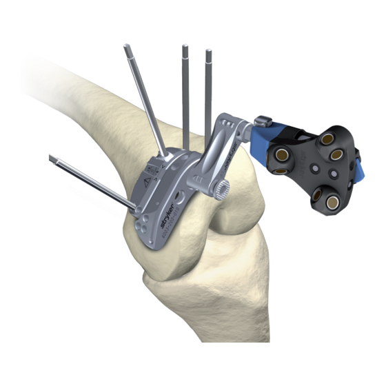
- Page 5 Instructions Release Button Tracker Adapter Cutting Guide 2 Mount Tracker Adapter on Cutting Guide 2.1 Press the release button and insert the base of Tracker Adapter into the cutting guide. 2.2 For tracker/camera alignment choose between the two adjustment angles of the Tracker Adapter on the cutting guide.
- Page 6 2.4 Double check that the Tracker Adapter is engaged and secure. CORRECT engaging Green marking is visible Tracker Adapter is flat on the Cutting Guide INCORRECT engaging ap between Tracker Adapter and Cutting Guide Green marking not visible...
- Page 7 Instructions 3 Mount Tracker on Tracker Adapter 3.1 Mount the tracker onto the interface of the Tracker Adapter. Note: The tracker in the below image is shown in principle. Cross pin must engage...
- Page 8 Hole for pin insertion Adjustment Block 4 Prealign and Prefixate Cutting Guide on Bone 4.1 Position the cutting guide on the bone with preadjusted varus/valgus, flexion/extension and resection level settings for preliminary fixation. 4.2 For preliminary fixation insert a pin into the swivel of the adjustment block as depicted in the detail above.
- Page 9 Instructions Holes (4 total) for pin insertion 6 Fixate Adjustment Block 6.1 Insert two pins into the adjustment block for fixation as depicted in the detail above. Ensure that the adjustment block is stable and can not move relative to the bone.
- Page 10 7 Adjust Resection Level 7.1 Use the screwdriver as depicted above for resection level adjustment. The scale is not calibrated. Refer to the navigation screen for adjustment. Holes (4 total) for pin insertion Cutting Block 8 Final Fixation of Cutting Block 8.1 Insert two pins into the cutting block for fixation as depicted in the detail above.
- Page 11 Instructions 9 Bone Cut 9.1 Insert the blade for cut. 9.2 Proceed to cut.
- Page 12 Disassembly Prior to cleaning and sterilization follow the instructions below for optimum cleaning and sterilization performance: 1 Remove tracker and Tracker Adapter. 2 Remove all pins. 3 Insert the screwdriver into the screwdriver interface. 4 Rotate the screwdriver until the cutting guide is set to the +4 marking. Cleaning, Disinfection, Sterilization and Inspection Instructions Cleaning group IV.
-
Page 13: Technical Specifications
For Use With WARNING Use only Stryker-approved products unless otherwise specified. For information related to compatible software applications, refer to the user manual of the software application. For information related to product-specific compatibility, refer to the table below. Product For use with... - Page 14 Troubleshooting Guidelines PROBLEM CAUSE ACTION The Tracker can not rotate or The interface is bent/ Return Tracker and Tracker be mounted onto interface and damaged. Adapter to service. does not lock in position. The Tracker Adapter does not The interface is bent/ Return Tracker Adapter and fit into cutting guide/jams.
-
Page 15: Definition Of Symbols
Definition of Symbols Symbol Name: Definition General warning sign: To signify a general warning. Caution: Indicates the need for the user to consult the instructions for use for important cautionary information such as warnings and precautions that cannot, for a variety of reasons, be presented on the medical device itself. - Page 16 U.S. Patents: www.stryker.com/patents Stryker Leibinger GmbH & Co. KG Bötzinger Straße 41 Stryker Corporation or its divisions or other affiliated 79111 Freiburg (Germany) entities own, use or have applied for the following t: +49 761 4512 0 (Germany) trademarks or service marks: Leibinger, Stryker. All...
Need help?
Do you have a question about the Navigated MIS Jig-A and is the answer not in the manual?
Questions and answers