Table of Contents
Advertisement
Operators Manual
MODEL:
HA-MKGL-60
HA-MKGL-80
HA-MKGL-100
HA-MKGL-60-CC
HA-MKGL-80-CC
HA-MKGL-100-CC
™
Cleveland
Enodis
Installation, Operation & Service
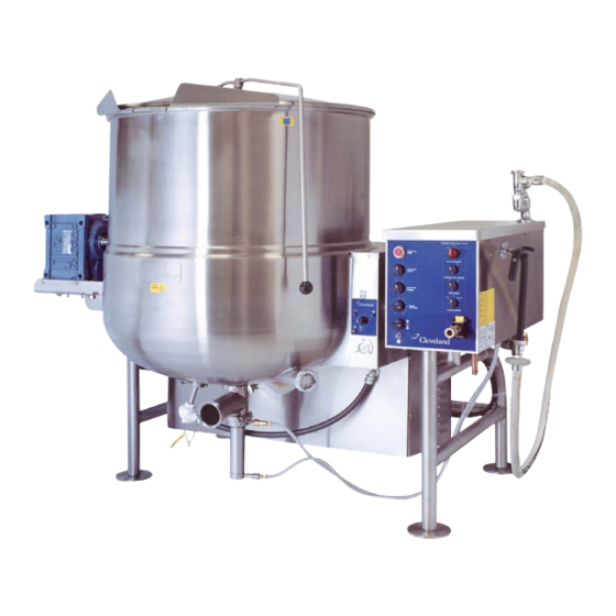
GAS MIXING KETTLES
HORIZONTAL AGITATOR
HA-MKGL-60-T
HA-MKGL-80-T
HA-MKGL-100-T
HA-MKGL-60-CC-T
HA-MKGL-80-CC-T
HA-MKGL-100-CC-T
1333 East 179th St., Cleveland, Ohio, U.S.A. 44110
Phone: (216) 481-4900 Fax: (216) 481-3782
Visit our web site at www.clevelandrange.com
SE95022 Rev. 5
Advertisement
Table of Contents

Related Manuals for Cleveland HA-MKGL-100


Summary of Contents for Cleveland HA-MKGL-100
- Page 1 Operators Manual Installation, Operation & Service MODEL: HA-MKGL-60 HA-MKGL-60-T HA-MKGL-80 HA-MKGL-80-T HA-MKGL-100 HA-MKGL-100-T HA-MKGL-60-CC HA-MKGL-60-CC-T HA-MKGL-80-CC HA-MKGL-80-CC-T HA-MKGL-100-CC HA-MKGL-100-CC-T ™ Cleveland Enodis GAS MIXING KETTLES HORIZONTAL AGITATOR 1333 East 179th St., Cleveland, Ohio, U.S.A. 44110 Phone: (216) 481-4900 Fax: (216) 481-3782 Visit our web site at www.clevelandrange.com...
-
Page 2: For The User
• Observe all clearance requirements. • Disconnect the electrical power supply to the appliance before cleaning or servicing unit. • All service must be performed by a qualified Cleveland Range Technician. • Do not obstruct the flow of combustion and ventilation air. -
Page 3: Gas Appliances
For your safety Keep clear of pressure relief discharge. Inspect unit daily for proper operation. Surfaces may be extremely hot! Use protective equipment. Do not lean on or place objects on kettle lip. Shut off power at main fuse disconnect prior to servicing. -
Page 4: Installation
INSTALLATION GENERAL Installation of the kettle must be accomplished by qualified installation personnel working to all applicable local and national codes. Improper installation of product could cause injury or damage. This equipment is built to comply with applicable standards for manufacturers. Included among those approval agencies are: UL, A.G.A., NSF, ASME/N.Bd., CSA, CGA, ETL, and others. -
Page 5: Warranty
It is recommended that a sediment trap (drip leg) be installed in the gas supply line. If the gas pressure exceeds 14” water column, a pressure regulator must be installed, to provide a maximum of 14” water column gas pressure to the gas control valve. Connect the gas supply piping to the input side of the gas control valve. - Page 6 68 3/8" NOTES: CLEVELAND RANGE EQUIPMENT IS BUILT TO COMPLY WITH APPLICABLE STANDARDS FOR MANUFACTURERS. INCLUDED AMONG THOSE APPROVAL AGENCIES ARE: UL, A.G.A., NSF, ASME/N.BD., CSA, CGA, ETL, AND OTHERS. INSTALLATIONS OF BACK FLOW PREVENTERS, VACUUM BREAKERS AND OTHER SPECIFIC CODE REQUIREMENTS ARE THE RESPONSIBILITY OF THE OWNER AND INSTALLER.
- Page 7 54 1/4" NOTES: CLEVELAND RANGE EQUIPMENT IS BUILT TO COMPLY WITH APPLICABLE STANDARDS FOR MANUFACTURERS. INCLUDED AMONG THOSE APPROVAL AGENCIES ARE: UL, A.G.A., NSF, ASME/N.BD., CSA, CGA, ETL, AND OTHERS. INSTALLATIONS OF BACK FLOW PREVENTERS, VACUUM BREAKERS AND OTHER SPECIFIC CODE REQUIREMENTS ARE THE RESPONSIBILITY OF THE OWNER AND INSTALLER.
-
Page 8: Operating Instructions
OPERATING INSTRUCTIONS Red Low Water Indicator Light When lit, in the upright position, indicates kettle gas burner has cut out and unit requires more water. Occasional pulsing of this light is normal. Green Heat Indicator Light When lit, indicates gas burner is on; cycles on-off with solid state controls. -
Page 9: Water Meter
General WARNING: Do not attempt to operate this appliance during a power failure. Keep appliance and area free and clear of combustibles. Before turning kettle on, ensure that following conditions exist: • If you are cooking an egg or milk product, do not pre-heat kettle. -
Page 10: Cleaning Instructions
CLEANING INSTRUCTIONS CAUTION SURFACES MAY BE EXTREMELY HOT! CARE AND CLEANING Cooking equipment must be cleaned regularly to maintain its fast, efficient cooking performance and to ensure its continued safe, reliable operation. The best time to clean is shortly after each use (allow unit to cool to a safe temperature). -
Page 11: Stainless Steel Equipment Care And Cleaning
STAINLESS STEEL EQUIPMENT CARE AND CLEANING (Suppied courtesy of Nafem. For more information visit their web site at www.nafem.org) Contrary to popular belief, stainless steels ARE susceptible to rusting. Corrosion on metals is everywhere. It is recognized quickly on iron and steel as unsightly yellow/orange rust. - Page 12 PRODUCT VALVE Daily - clean product valve as follows: KETTLE Open product valve. Disconnect air hoses. Remove air cylinder. Remove valve tee. Remove all O-rings. Clean air cylinder, do not submerge in water. Wipe clean and sanitize. Clean and sanitize tee and O-rings. Grease and reinstall O-rings.
- Page 13 AGITATOR To remove and clean agitator (two-person job): Agitator shaft Coupling Removing Agitator Remove scraper blades. Rotate agitator until pull pin is on top side. Turn power OFF. Pull pin out. Slide coupling toward kettle wall, and carefully lift agitator pulling back to lift out. Clean in a sink, using a warm water and mild detergent solution.
-
Page 14: Service Parts
SERVICE PARTS SCRAPER BLADES ITEM NO. PART NO. KE54602 KE54608 KE01976 AGITATOR SEAL ASSEMBLY ITEM PART NO. DESCRIPTION KE01911 RETAINING KNOBS ..3 KE54592 SEAL RETAINER PLATE . . 1 FA05002-8 "O" RING ....1 KE54594 PIN . -
Page 15: Pressure Relief Assembly
PRESSURE RELIEF ASSEMBLY ITEM NO. PART NO. FA05049 FI00151 FI00178 KE54941-5 KE54941-31 KE54223 SIGHT GLASS ITEM ON. PART NO. DESCRIPTION KE50955 KE52871 KE51053-1 FA05002-30 DESCRIPTION MALE CONNECTOR, 1/2" PIPE - 1/4" TUBE ......1 STREET ELBOW, 1/2"... -
Page 16: Hinge Assembly
HINGE ASSEMBLY ITEM NO. PART NO. 1. - 11 KE50597-1 KE50597-2 KE50597-3 KE50597-4 KE50597-5 KE50822 KE51217 KE50121-2 KE50121-1 KE50823-1 KE50824 KE50819-1 KE50820 KE50819 FA11284 FA11507 SK50418 KE50151-2 DESCRIPTION Hinge Assembly 25 - 40 Gallon, 20 Gallon Full Jacketed .......1 60 - 80 Gallon, 30 - 40 Gallon Full Jacketed . - Page 17 WATER METER ASSEMBLY ITEM ON. PART NO. FI00096 F100629-2 FI00063 F100629-36 KE55228 KE54834-4 KE02290 R00179 FI00365 FI00267 FA21008 KE54336 KE54336-1 KE52002-1 DESCRIPTION 3/4 BRASS UNION ..........3 3/4 NPT X 2 112 BRASS NIPPLE .
-
Page 18: Flush Piston Valve
FLUSH PISTON VALVE ITEM NO. PART NO. DESCRIPTION T40430 Valve Assembly (includes parts 1 - 16) ......1 FA05000 "O"... - Page 19 FLUSH PISTON VALVE & TEMPERATURE SENSOR ASSEMBLIES (USED AFTER TO 2003) ITEM ON. PART NO. KE55210 FI05144-3 KE52154-4 KE02291 KE55248 KE55249 KE55250 KE55251 KE55252 KE55253 KE55254 FA05002-53 KE55256 KE54924 FA05002-46 KE52154-3 AIR VALVE ASSEMBLY FPVA-3 DESCRIPTION WELD RING, KETTLE BOTTOM OUTLET ......1 SANI CLAMP, 3”...
- Page 20 GEARMOTOR - ELECTRICAL ASSEMBLY ITEM NO. PART NO. KE53838-2 KE50750-2 KE51139-1 KE52936-18 PR50003 PR50005 KE54528 KE54527-1 KE54527-2 DESCRIPTION TRANSFORMER, 200-240V/440-480V ....... .1 CONTACTOR .
- Page 21 KETTLE - ELECTRICAL COMPONENTS ITEM ON. PART NO. KE53838-19 KE53444 KE54833-3 KE02372 KE53469-4 KE00458 KE50303 KE50753-7 KE55069-6 FI05050 KE02400 KE55453-1 KE53838-20 DESCRIPTION TRANSFORMER, 120-16V......... .1 TRANSFORMER BRACKET .
- Page 22 KETTLE - GAS COMPONENTS 10 26...
- Page 23 ITEM ON. PART NO. KE53617 KE53437 KE50556-2 KE00515 FI05213 FA05002-4 KE53422 GAS ORIFICE: KE53403-6 KE53403-7 KE53403-10 KE53403-11 KE53403-10 KE53403-14 KE53403-17 KE53403-18 KE53403-17 KE53403-22 FA05002-29 KE50568-1 KE50567-1 TEMPERATURE CONTROL ASSEMBLY: KE50569-1 SE00114 KE51005 KE50429-2 KE53441 KE53441-1 KE01426-1 KE53402-1 FI05212 KE95087-1 KE50567-2 KE02274 KE53618 KE53619...
- Page 24 CONTROL BOX - ELECTRICAL For front panel control switches see - SIDE BOX - TILT MECHANISM & SWITCHES. CONTROL BOX - WATER METER & CHART RECORDER. 13 17 18 10 SAFETY SAFETY SWITCH SWITCH ASSEMBLY - ASSEMBLY - FRONT SIDE VIEW VIEW 16 11 12 13...
- Page 25 ITEM ON. PART NO. KE55287-1 KE55187-2 KE55287-3 KE55287-4 KE55284-1 KE55284-2 KE55286-1 KE55286-2 KE54860 KE55283 KE55288-1 KE55288-2 KE55298 KE50750-4 KE50750-2 KE55297-1 KE55297-2 KE55297-3 KE55285 FA40000-15 FA21007 FA32006 FA11091 FA21004 FA11146 FA40000-14 FA21006 KE55271 KE55292-1 KE55292-4 KE55292-3 KE50753-10 KE52106 KE50377 KE50376 KE50374 SK50055-1 SK50054-1 KE54761-2...
- Page 26 CONTROL BOX - WATER METER & CHART RECORDER ITEM NO. PART NO. KE53257 SE50354 SE50354 KE003209-1 KE003209-1 KE003209-6 KE003209-7 KE53136-1 MAIN POWER INCLUDED WITH ALL SWITCHES. DESCRIPTION Digital Counter ..........1 Pen Tip, red (pkg.
- Page 27 SIDE BOX - PNEUMATICS ITEM NO. PART NO. FA05166 KE54280 FA30512 FA32500 KE52697 KE52931 F100178 FI00351 FI05318 FI00151 FA30090 7100595-8 KE55238 F105220-1 FA21006 KE532177 KE532176 FA30000 KE02292 KE50555-3 FA21008 FA30002 (NOT SHOWN) RTV ALL AROUND DESCRIPTION QUICK CONNECT ..........1 SLIDE VALVE .
- Page 28 SIDE BOX - TILT MECHANISM & SWITCHES SEE PNEUMATIC SEE PNEUMATIC COMPONENTS DRAWING COMPONENTS DRAWING ITEM NO. PART NO. DESCRIPTION KE50579-1 CIRCUIT BREAKER ..........1 FA00012 "O"...
- Page 29 FA10772 FA20048 FA95007-4 FA95055-1 FA19201 KE54644 KE52836-2 KE50315 FA95005 KE52193-1 KE52192 KE52191 FA30088 FA95008 KE50582 FA95055-6 KE50583 KE52832-1 FA10487 FA31008 FA20026 KE50473 FO1518-1 KE02053 FI05223-1 FI05222 FI05231 FI05226-11 KE51007 FA10139 KE50498 FA32004 KE603208-7 KE603208-9 KE50581 KE54535 KE50753-10 KE54491 KE53599-8 KE53599-9 FA95062 FA95074 FA19177...
-
Page 30: Inspection And Maintenance Checklist
MAINTENANCE INSPECTION AND MAINTENANCE CHECKLIST Cleveland Range equipment requires little preventative maintenance. We do however provide the following chart as a guide line for inspection and maintenance to keep your unit functioning at 100%. MONTHLY INSPECTION Inspect all switches for damage. Replace rubber boots or switches as required. - Page 31 OPERATING SEQUENCE - HEATING STEP ACTION Close main circuit breaker. On/Off switch on kettle switched to ON. Control box. 12 VDC relay contacts close. Ignition module. 120 volts turned off to ignitor. Temperature reached. QUICK CHECKS: Potentiometer - Range 0 - 50K, Safety Thermostat - Normally Closed, Thermistor - Range 0 - 100K, Water Level Probe - Must be submerged in water for burners to work OPERATING SEQUENCE - AGITATOR On/Off switch closed.
-
Page 32: Kettle Safety Inspection Checklist
KETTLE SAFETY INSPECTION CHECKLIST Regular inspection and maintenance of units is essential to obtain trouble free and safe operation of equipment. Inspections must include testing of the pressure relief valve and checks of the operating system to insure that it has not been altered. No safety features designed into the equipment should ever be tampered with. -
Page 33: Safety Thermostat
SAFETY THERMOSTAT: ✔ Probe fully inserted in tube Wiring is properly connected Low Water Level Probe: ✔ Probe properly attached Operating Thermostat: 260º - 270º ✔ 265º MAXIMUM KETTLE TEMPERATURE If maximum temperature is not in this range (on empty kettle), refer to the CALIBRATING PROCEDURE. -
Page 34: Air Filter Replacement Procedure
AIR FILTER REPLACEMENT PROCEDURE Disconnect air supply and bleed system. Remove cover on console (see SIDE BOX - PNEUMATICS). 3. Check for filter location. 4. Push lever down and rotate bowl/ guard assembly 1/8 turn. 5. Push down on Deflector bowl/guard assembly Filter... -
Page 35: Oil Filling Procedure
PRODUCT VALVE Replacing O-Rings KETTLE Open product valve. Disconnect air hoses. Remove air cylinder. Remove valve tee. Remove all O-rings, grease and reinstall new O-rings as required. Reinstall tee to kettle outlet. Reinstall air cylinder to bottom of tee. Reconnect air hoses. Close valve and check for alignment. -
Page 36: Kettle Venting Instructions
KETTLE VENTING INSTRUCTIONS The following venting procedure should be followed when the Vacuum/Pressure Gauge needle is in the "VENT AIR" zone: NOTE: Check for and eliminate leaks prior to venting (See REPAIRING LEAKS IN STEAM JACKETED KETTLE FITTINGS). DANGER: DANGER: 1. -
Page 37: Reservoir Fill Procedures
RESERVOIR FILL PROCEDURES WARNING: The kettle's water level must be maintained at the proper level. Under normal operating conditions, the sealed water reservoir should never require the addition of water. If the red "low water" light comes on during use (while the kettle is in an upright position), the water level has reached a critically low level. -
Page 38: Pressure Relief Valve Periodic Testing
PRESSURE RELIEF VALVE PERIODIC TESTING Most insurance agencies require periodic testing of pressure relief valves used on pressure vessels. This procedure will allow you to safely and quickly test your kettle's pressure relief valve. We recommend this test be performed twice a year. DANGER: DANGER: NOTE: The following instruction is intended for use by... -
Page 39: Kettle Jacket Filling & Draining Procedures
KETTLE JACKET FILLING & DRAINING PROCEDURES Under normal circumstances the kettle does not require the draining of all fluid. If the red “low water” light is on, follow the RESERVOIR FILL PROCEDURES in this manual. If unit must be drained follow the procedures described on the following pages. - Page 40 HA DRIVE SHAFT REPLACEMENT PROCEDURE Note: Disconnect external power supply and shut off gas to unit prior to servicing. 1. Remove mixer arm leaving flat surface on drive shaft facing upwards. 2. Remove shaft end cap. 3. Remove shaft retaining bolt. 4.
- Page 41 5. Gently hammer out shaft and remove. 6. Clean seal. 7. Grease seal with food grade grease. 8. Insert new shaft. 9. Push new shaft past retraining ring groove and install retaining ring. 10. Tap shaft back to seat up against retaining ring. 11.
-
Page 42: Field Conversion Instructions
FIELD CONVERSION INSTRUCTIONS - Natural Gas to Propane Gas Power Burner Gas Kettles 140000 140000 190000 190000 NOTE: Use thread sealant compatible with propane gas on all threaded piping connections. Disconnect electrical connection. Shut off main gas supply and disconnect kettle from supply line. -
Page 43: Spare Parts List
SPARE PARTS LIST The following is a spare parts listing of parts that wear during normal us or are apt to be misplaced during normal operation. These parts should be kept on hand to prevent loss time due to a minor problem. PART NUMBER DESCRIPTION KE54602... - Page 44 AC INVERTER PROGRAMMING INSTRUCTIONS The WFC Series AC Inverters come wired for external use and must be installed for use in a side panel control (See WIRING DIAGRAMS). Refer to owners manual for complete instructions and explanations. Manual used for the following was FORM 1094.
- Page 45 DEC1 Deceleration Time #1 ACC2 Acceleration Time #2 DEC2 Deceleration Time #2 DECTL Torq. Limit Response Time DCBRK DC Brake Time DCVLT DC Brake voltage VSEL V/Hz Characteristic Selector BOOST Torque Boost FKNEE V/Hz Knee Frequency SKBND Skip Fresq. Hysteresis Band Skip Frequency #1 Skip Frequency #2 Skip Frequency #3...
- Page 46 WIRING DIAGRAM - DUAL REMOTE...
- Page 47 WIRING DIAGRAM - SINGLE REMOTE...
Need help?
Do you have a question about the HA-MKGL-100 and is the answer not in the manual?
Questions and answers