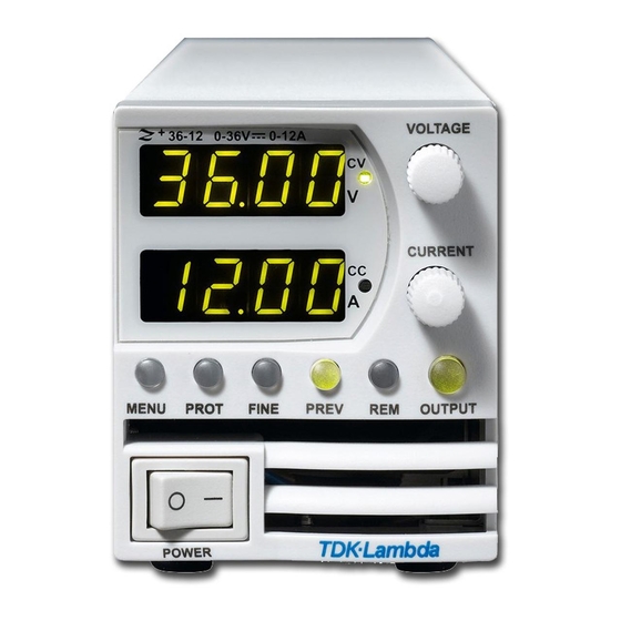
Summary of Contents for TDK-Lambda Z+ Series
- Page 1 Series Programmable DC Power Supplies 200W/400W/600W/800W in 2U Built-in USB, RS-232 & RS-485 Interface User Manual Optional Interface: IEEE488.2 SCPI (GPIB) Multi-Drop...
- Page 2 USER MANUAL FOR IEEE Programming Interface POWER SUPPLIES Manual Supplement Refer to the Z Technical Manual for information on installing the power supply, safety requirements, specifications, operating the front panel, using the serial RS-232/485, USB programming and the analog programming. IA710-04-03E...
-
Page 3: Table Of Contents
Table of Contents INTRODUCTION ......................3 SCOPE OF MANUAL .....................3 CHAPTER 1: THE IEEE-488.2 INTERFACE ..............3 CHAPTER 2: CONNECTION ..................4 2.1 Point to Point ............................4 2.2 Multi Drop ............................4 2.2.1 Selecting One Power Supply in a Multi Drop Chain ................4 2.3 Communication Cables ........................ -
Page 4: Introduction
INTRODUCTION The internal factory installed General Purpose Interface Bus (GPIB) allows operation of the Z Power Supply from a computer via IEEE-488. The interface allows the user complete remote control of the Power Supply, including output voltage and current setting and monitoring, protection setting, trigger, waveform list operation, Power Supply status and SRQ reporting. -
Page 5: Chapter 2: Connection
CHAPTER 2: CONNECTION This section provides information on variable IEEE (GPIB) connection modes, communication cables and selecting communication parameters for operation via IEEE (GPIB) interface. It is possible connect to IEEE (GPIB) interface in two ways. 2.1 Point to Point One IEEE Interface can control only one Z Power Supply. -
Page 6: Chapter 3: Configuration
CHAPTER 3: CONFIGURATION 3.1 Configuration the IEEE Controller A typical IEEE controller is a personal computer with an IEEE interface card. Each card vendor supplies its own configuration instructions and interface software. Each time the software is executed, the controller is configured as follows: Controller Address = Power Supply address. -
Page 7: Configuration The Power Supply
3.2 Configuration the Power Supply Refer to Fig.3-1. 3.2.1 To Select the Communication Interface 1. Press REM button. The LED is illuminated. “INtF" appears on Voltage display. 2. Press Voltage Encoder. Existing communication mode appears on Current display. 3. Turn Current Encoder until desired message appears; "IEEE" (for unit with IEEE option) or "485". 4. -
Page 8: Chapter 4: Programming Commands
CHAPTER 4: PROGRAMMING COMMANDS Communication over the GPIB interface meets IEEE 488.2 standards and is Standard Commands for Programmable Instrumentation (SCPI) compliant. 4.1 SCPI Protocol Refer to section 7.10 of Z series User Manual 4.2 SCPI Common Commands Common commands are used to control instrument status registers, status reporting, synchronization, data storage, and other common functions. -
Page 9: Scpi Subsystem Commands
4.3 SCPI Subsystem Commands Subsystem commands control all Z functions. For a full command description refer to section 7.12 in Z series User Manual. Short list of Z series commands: SCPI Command Description ABORt Aborts the triggered action DISPlay [:WINDow]:STATe <bool> Display ON/OFF* [:WINDow]:FLASh <bool>... - Page 10 [SOURce] :CURRent [:LEVel] [:IMMediate] [:AMPLitude] <NRf+> Set the output current* :TRIGger <NRf+> Set the triggered output current* :MODE NONE|FIX|LIST|WAVE Select arbitrary trigger control mode* :VOLTage [:LEVel] [:IMMediate] [:AMPLitude] <NRf+> Set the output voltage* :TRIGger <NRf+> Set the triggered output voltage* :PROTection :LEVel <NRf+>...
-
Page 11: The Summary Registers
SYSTem :ERRor:ENABle Enable error message :ERRor? Read system error messages :LANGuage GEN Set communication language* :REMote [:STATe] LOC|REM|LLO Set the remote/local state* :VERSion? Returns software revision :DATE? Returns calibration date :PON :TIME? Response time from last reset TRIGger [:STARt] Run trigger :DELay <NRf+>... -
Page 12: Output Queue
4.5 Output Queue Refer to section 9.6.16 of Z series User Manual. 4.6 Error Messages Refer to section 9.6.17 of Z series User Manual. 4.7 Execution Time Command execution time except for *CLS (150mS) is less than 15 milliseconds. INST:NSEL 06 11 millisecond OUTP:STAT ON 12 millisecond... -
Page 13: Register Structure
4.8 Register Structure Fig.4- 1: Status Register and SRQ Tree... - Page 14 Fig.4‐2: Instrument Summary Register Tree for Multi Drop Mode...
-
Page 15: Chapter 5: Communication Example
CHAPTER 5: COMMUNICATION EXAMPLE This section provides an example the National Instruments™ MAX program to communicate with the Z 1. Run National Instruments™ MAX (Measurement & Automation Explorer) program 2. Select “Devices and Interfaces” -> “GPIB0” press Scan for Instruments. Refer to Fig.5-1 Fig.5-1: Scanning for Instrument 3. - Page 16 4. Click Communicate with Instrument in the GPIB Explorer toolbar. NI-488.2 Communicator appears. Refer to Fig. 5-3 Fig.5-3: ID String Query 5. In the Send String box, *IDN? appears. Click Query. The ID string indicates the model, serial number, firmware version and the GPIB card firmware version. This will be shown in the text box below String Received.
- Page 17 NOTES...
- Page 18 Fax: +81-3-5201-7287 www.tdk-lambda.com CHINA TDK-Lambda UK Ltd. Kingsley Avenue Ilfracombe, Devon Shanghai Branch of Wuxi TDK-Lambda Electronic Co. Ltd. EX 34 8ES United Kingdom 28F, Xingyuan Technology Building No.418, Guiping Road, Shanghai, China 200233 Tel: +44-1271-856666 Fax: +44-1271-864894 E-mail: powersolutions@uk.tdk-lambda.com Tel: +86-21-6485-0777 Fax: +86-21-6485-0666 www.uk.tdk-lambda.com...


Need help?
Do you have a question about the Z+ Series and is the answer not in the manual?
Questions and answers