Advertisement
Quick Links
Instruction Manual
BEFORE USING THE POWER SUPPLY UNIT
Pay attention to all warnings and cautions before using the unit. Incorrect usage could lead to an electrical
shock, damage to the unit or a fire hazard.
WARNING and CAUTION
● Do not modify.
● Do not touch the internal components, they may have high voltage or high temperature. You may get elec-
trical shock or burned.
● When the unit is operating, keep your hands and face away from it, you may get injured by an accident.
● This power supply is primarily designed and manufactured to be used and enclosed in other equipment.
Stick the WARNING label for users on the system equipment and describe the notice in the instruction
manual.
● Never operate the unit under over current or shorted conditions for 30 seconds or more and except Input
Voltage Range in specification which could result in damage or insulation failure or smoking or burning.
● Confirm connections to input/output terminals are correct as indicated in the instruction manual.
● This powersupply is PC board type unit. Please hold the board edge while mouting, and do not touch the
component side. In using the apparatus, please lift the power supply with a metal spacer.
● Do not drop or apply shock to power supply unit.
Note: CE MARKING
CE Marking, when applied to a product covered by this handbook, indicates compliance with the low voltage
directive.
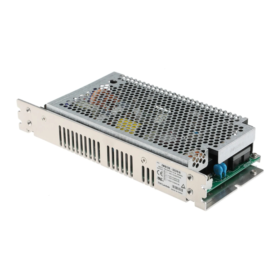
ZWQ Series
ZWQ80/130
TDK-Lambda
ZWQ Series
INSTRUCTION MANUAL
A190-04-01C
Advertisement

Subscribe to Our Youtube Channel
Related Manuals for TDK-Lambda ZWQ Series


Summary of Contents for TDK-Lambda ZWQ Series
- Page 1 TDK-Lambda ZWQ Series INSTRUCTION MANUAL ZWQ Series ZWQ80/130 Instruction Manual BEFORE USING THE POWER SUPPLY UNIT Pay attention to all warnings and cautions before using the unit. Incorrect usage could lead to an electrical shock, damage to the unit or a fire hazard.
- Page 2 TDK-Lambda ZWQ Series INSTRUCTION MANUAL 1. Terminal Explanation ZWQ80 ① L; AC Input terminal Live line ( Fuse in line ) ⑩ VR51; Output voltage of V1 adjustment trimmer ⑪ VR81; Output voltage of V4 adjustment trimmer CN1 - 1 ②...
- Page 3 TDK-Lambda ZWQ Series INSTRUCTION MANUAL ZWQ130 ① L; AC Input terminal Live line ( Fuse in line ) ⑩ VR51; Output voltage of V1 adjustment trimmer ⑪ VR81; Output voltage of V4 adjustment trimmer CN1 - 1 ② N; AC Input terminal Neutral line...
- Page 4 TDK-Lambda ZWQ Series INSTRUCTION MANUAL 2. Terminal connecting method · Input must be off when making connections. · Connect FG terminal of input connector and mountable FG to ground terminal of the equipment. · Output current of each connector pin must be less than 5A.
- Page 5 TDK-Lambda ZWQ Series INSTRUCTION MANUAL ZWQ130 * Input & Output connector ( J.S.T. ) ZWQ130 Connector Housing Terminal Pin Input(CN1) B3P-5-VH VHR-5N SVH-21T-P1.1 Output(CN51) B8P-VH VHR-8N SVH-21T-P1.1 Output(CN61) B3P-VH VHR-3N SVH-21T-P1.1 Output(CN81) B6P-VH VHR-6N SVH-21T-P1.1 * Output Current of each connector pin must be less than 5A.
- Page 6 TDK-Lambda ZWQ Series INSTRUCTION MANUAL 3. Explanation of Functions and Precautions 3-1. Input Voltage Range 3-6. Over Voltage Protection ( OVP ) Input voltage range is single phase 85 ~ 265VAC ( 47 ~ The OVP function ( Inverter shut down method, manual 63Hz ) or 120 ~ 370VDC.
-
Page 7: Primary Side
A connector( CN2 ) for ON/OFF control is provided in 3-9. Peak Output Current the Primary Circuit. When using CN2, safety standard For ZWQ series, relation between maximum output cur- requirements should be considered in application design rent (Convection cooling) and peak output current must or choice of switch, relay or connector. - Page 8 TDK-Lambda ZWQ Series INSTRUCTION MANUAL Input ~ FG ( chassis ) : solid line The control mode is shown below. Input ~ Output : dotted line The control mode is shown below.+ R & - R termi- Output Condition nal condition SW ON ( Higher than 4.5V )
-
Page 9: Output Derating
TDK-Lambda ZWQ Series INSTRUCTION MANUAL 5. Mounting Directions 5-1. Output Derating according to the Mounting Directions Recommend standard mounting is method ( A ). Method ( B ), ( C ), ( D ), ( E ) are also possible. Refer to the derat- ing below. - Page 10 TDK-Lambda ZWQ Series INSTRUCTION MANUAL ZWQ130 (% ) LOAD(%) Mounting M ounting(A) - 10~ 25℃ M ounting(B ),(C),(D ) 30℃ Mounting(E) 35℃ 40℃ 45℃ 50℃ 55℃ 50 60 60℃ T a (℃ ) Total allowable output power(W) (Monuting A) 40℃...
- Page 11 5-2. Output Derating according to the Mounting Directions for with Cover type ZWQ series has option that with Cover type ( /A ). Recommend standard mounting is method ( A ). Method ( B ), ( C ), ( D ), ( E ) are also possible. Refer to the derating below. Please do not use installation method ( F ), where the PCB will be on the top side and heat will be trapped inside the unit.
- Page 12 TDK-Lambda ZWQ Series INSTRUCTION MANUAL With Cover ( Convection cooling ) ZWQ80/A (% ) LOAD (%) Mounting M ounting(A) - 10 ~ 15 ℃ M ounting(B ),(C),(D) 20 ℃ M ounting(E) 25 ℃ 30 ℃ 35 ℃ 40 ℃ 45 ℃...
- Page 13 TDK-Lambda ZWQ Series INSTRUCTION MANUAL Each allowable output Muximum output Output power (W) current(A) voltage 30℃ 40℃ 50℃ 30℃ 40℃ 50℃ 522* 56.2 37.5 11.2 +12/+15 48/60 36/45 24/30 -12/-15 48/60 36/45 24/30 5223 24.7 16.5 5225 26.2 5222 5224 With Cover ( Forced air cooling ) ZWQ80/A・ZWQ130/A...
- Page 14 TDK-Lambda ZWQ Series INSTRUCTION MANUAL ZWQ130/A (Mounting A) Each allowable output Muximum output Output power(A) current (A) voltage 40℃ 50℃ 60℃ 40℃ 50℃ 60℃ 522* 71.2 47.5 14.2 +12V/+15 60/75 45/56.2 30/37.5 -12V/-15 60/75 45/56.2 30/37.5 5223 39.6 29.7 19.8...
- Page 15 TDK-Lambda ZWQ Series INSTRUCTION MANUAL ZWQ130 5-2. Mounting Method PCB type Please use the mounting hole as: ZWQ80 : 5 holes of φ3.5 ZWQ130 : 4 holes of φ3.5 and insert the spacer (MAXφ6.0)of height over 8mm to lift the unit. Also use all mounting holes for the unit installation.
- Page 16 For safety and EMI considerations, connect FG terminal of input connector and mountable FG of ZWQ series to mounting set ground terminal at 9. Notes equipment. 1) Over voltage Category II.
Need help?
Do you have a question about the ZWQ Series and is the answer not in the manual?
Questions and answers