
Related Manuals for TDK-Lambda Z160-1.3


Summary of Contents for TDK-Lambda Z160-1.3
- Page 1 Series Programmable DC Power Supplies 200W/400W/600W/800W in 2U Built-in USB, RS-232 & RS-485 Interface Optional Interface: LAN IEEE488.2 SCPI (GPIB) Multi-Drop Isolated Analog Programming User Manual...
- Page 2 Series Programmable DC Power Supplies 200W/400W/600W/800W Built-in USB, RS-232 & RS-485 Interface USER MANUAL This Manual Covers Models: Z160-1.3 Z320-0.65 Z650-0.32 Z160-2.6 Z320-1.3 Z650-0.64 Z160-4 Z320-2 Z650-1 Z160-5 Z320-2.5 Z650-1.25 IA779-04-01...
- Page 4 DECLARATION OF CONFORMITY Z+ series We, TDK-Lambda Ltd., located at Haharoshet St. 56 Industrial Zone P.O.B. 500 Karmiel, Israel declare under our sole responsibility that the Z200 series, Z400 series, Z600 series and Z800 series as detailed on the products covered sheet comply with the provisions of the following European...
- Page 5 This page intentionally left blank...
-
Page 6: Table Of Contents
Table of Contents REGULATORY NOTICES SAFETY INSTRUCTIONS CHAPTER 1: GENERAL INFORMATION 1.1 User Manual Content ........................15 1.2 Introduction ............................. 15 1.2.1 General Description ........................... 15 1.2.3 Features and Options ..........................15 1.2.4 Multiple Output Power System ......................16 1.2.5 Control via the USB or RS232/485 Communication Ports ..........16 1.2.6 Analog Voltage Programming and Monitoring ............... - Page 7 3.9.6 Making the Load Connections ......................43 3.9.7 Connecting Single Loads, Local Sensing (default) ..............45 3.9.8 Connecting Single Loads, Remote Sensing ................. 45 3.9.9 Connecting Multiple Loads, Radial Distribution Method ............ 46 3.9.10 Multiple Load Connection with Distribution Terminals ............. 46 3.9.11 Grounding Outputs ..........................
- Page 8 5.4 Series Operation ..........................65 5.4.1 Series Connection for Increased Output Voltage..............65 5.4.2 Series Connection for Positive and Negative Output Voltage ......... 66 5.4.3 Remote Programming in Series Operation ................. 66 5.5 Parallel Operation .......................... 67 5.5.1 Introduction ..............................67 5.5.2 Basic Parallel Operation ...........................
- Page 9 7.7.2 End of Message .............................. 87 7.7.3 Command Repeat ............................87 7.7.4 Checksum ................................87 7.7.5 Acknowledge ..............................87 7.7.6 Backspace ................................87 7.7.7 Error Messages ..............................87 7.8 GEN Command Set Description ....................88 7.8.1 General guides ............................... 88 7.8.2 Command Set Categories ........................
- Page 10 8.6.2 Wave Execution via Communication PC ..................125 8.6.3 Wave Execution via Front Panel .......................126 8.7 Additional Examples ........................126 8.7.1 List Example ..............................126 8.7.2 Waveform Example ............................126 CHAPTER 9: STATUS, FAULT AND SRQ REGISTERS 9.1 General ............................. 127 9.2 Power Supply Status Structure ....................128 9.3 Condition Registers........................
-
Page 11: Trademark Information
QA seal has been removed or altered by anyone other than TDK-Lambda authorised personnel. TDK-Lambda does not warrant the buyers circuitry or malfunctions of TDK-Lambda products resulting from the buyer’s circuitry. -
Page 12: Regulatory Notices
EN 61010-1 - ”Electrical Equipment For Measurement, Control and Laboratory Use; Part 1: General Requirements. ” A ”Declaration of Conformity” in accordance with the preceding directives and standards has been made and is on file at our EU representative TDK-Lambda UK, located at Kingsley Avenue, Ilfracombe, Devon EX34 8ES, UK. - Page 13 Die Geräte der Z Serie sind ohne ausdrückliche schriftliche Genehmigung des Geschäftsführers von TDK-Lambda nicht für die Benutzung als kritische Komponente in nuklearen Steuerungssystemen, lebenserhaltenden Systemen oder Geräten für den Einsatz in gefährlichen Umgebungen zugelassen. OVERVOLTAGE CATEGORY AND ENVIRONMENTAL CONDITIONS The Z series units have been evaluated to Overvoltage category II.
-
Page 14: Z + 200 Series Specifications
PARTS SUBSTITUTIONS & MODIFICATIONS Parts substitutions and modifications are by authorized TDK-Lambda service personnel only. For repairs or modifications, the instrument must be returned to TDK-Lambda service facility. AUSWECHSELN UND VERÄNDERUNG VON BAUTEILEN Das Auswechseln sowie die Veränderung von Teilen darf nur von autorisierten TDK-Lambda Servicemitarbeitern durchgefuhrt werden. - Page 15 WARNING: There is a potential shock hazard when using a power supply with output voltage greater than 60VDC. Do not turn ON power supply when output voltage above 60VDC without output plug protection assembled. Turn OFF power supply or disconnect power supply from AC mains before making or changing any rear panel connection.
-
Page 16: Chapter 1: General Information
USB and RS232/485. LAN, IEEE and Isolated-Analog programming/monitoring are optional. 1.2.2 Models Covered by this Manual Model Voltage range (V) Current range (A) Z160-1.3 0-160 0-1.3 Z160-2.6 0-160 0-2.6... -
Page 17: Multiple Output Power System
1.2.4 Multiple Output Power System The Z Series power supplies series can be configured into a programmable power system of up to 31 units using the built-in USB or RS232/RS485 communication port in the power supply and the RS485 linking cable provided with each power supply. In a LAN system, each power supply can be controlled using the optional LAN controller (factory installed). -
Page 18: Accessories
CAUTION: Observe all torque guidelines within this manual. Over torque may damage unit or accessories. Such damage is not covered under manufacturers warranty. 1.3 Accessories 1.3.1 General Accessories are delivered with the power supply or separately upon ordering, The list below shows the possible accessories and ordering numbers. -
Page 19: Chapter 2: Specifications
CHAPTER 2: SPECIFICATIONS... - Page 27 Pages 26~33 are reserved for Z600/800W...
- Page 28 Pages 26~33 are reserved for Z600/800W...
-
Page 29: Z200W/400W/600W/800W Outline Drawing
2.6 Z200W/400W/600W/800W Outline Drawing... -
Page 30: Z200W/400W/600W/800W Optional Ieee, Isolated Analog Interface Outline Drawing
2.7 Z200W/400W/600W/800W Optional IEEE, Isolated Analog Interface Outline Drawing... - Page 31 This Page intentionally left blank...
-
Page 32: Chapter 3: Installation
Keep all packing material until the inspection has been completed. If damage is detected, file a claim with carrier immediately and notify the TDK-Lambda sales or service facility nearest you. 3.4 Rack Mounting The Z power supply series is designed to fit in a standard 19”... -
Page 33: Location, Mounting And Cooling
3.5 Location, Mounting and Cooling This power supply is fan cooled. The air intake is at the front panel and the exhaust is at the rear panel. Upon installation allow cooling air to reach the front panel ventilation inlets. Allow minimum 10cm (4”) of unrestricted air space at the front and the rear of the unit. -
Page 34: Ac Input Cord
3.7.2 AC Input Cord Refer to section 1.3.4 for details of the AC input cords recommended. WARNING: The AC input cord plug is the disconnect device of the power supply. The plug must be readily identifiable and accessible to the user. The AC input cord must be no longer than 3m. WARNUNG: Die Stromversorgung wird durch Ziehen des Netzkabels vom Versorgungsnetz getrennt. -
Page 35: Constant Voltage Check
3.8.3 Constant Voltage Check Turn on the output by pressing OUTPUT button so the OUTPUT LED illuminates. Observe the power supply Voltage display and rotate the Voltage encoder. Ensure that the output voltage varies while the Voltage encoder is rotated. The minimum control range is from zero to the maximum rated output for the power supply model. -
Page 36: Foldback Check
3.8.7 Foldback Check WARNING: There is a potential shock hazard when checking a power supply with output voltage greater than 60VDC. Observe proper safety procedures during the checking. WARNUNG: Beim Einsatz eines Netzteils mit einer Nenn-Ausgangsspannung von mehr als 60VDC besteht Stromschlaggefahr. -
Page 37: Current Carrying Capacity
3.9.2 Current Carrying Capacity Two factors must be considered when selecting the wire size: 1. Wires should be at least heavy enough not to overheat while carrying the power supply load current at the rated load, or the current that would flow in the event the load wires were shorted, whichever is greater. -
Page 38: Wire Termination
3.9.3 Wire Termination The wires should be properly terminated with terminals securely attached. DO NOT use non terminated wires for load connection at the power supply. CAUTION: When local sensing, a short from +LS or +S to -V or -S or -LS, will cause damage to the power supply. Reversing the sense wires might cause damage to the power supply in local and remote sensing. - Page 39 160V to 650V Models The 160V to 650V models have four terminal wire clamp output connector. The two left terminals are positive outputs and the other two right terminals are the negative outputs. The connector requirements are as follows: 1. Connector type: IC 2,5/ 4-G-5,08 (Phoenix). 2.
-
Page 40: Connecting Single Loads, Local Sensing (Default)
Bei Einsatz einer Stromversorgung größer 60VDC Nennspannung besteht eine potentielle Gesundheitsgefahr durch elektrischen Schlag. Schalten Sie keine Stromversorgung mit einer Ausgangsspannung größer 60VDC EIN, ohne dass die Schutzabdeckung des Ausgangssteckers montiert ist. Stellen Sie sicher, dass die Schutzabdeckung des Ausgangssteckers fachgerecht montiert wurde und wie in Bild 3.5. -
Page 41: Connecting Multiple Loads, Radial Distribution Method
3.9.9 Connecting Multiple Loads, Radial Distribution Method Fig.3-8 shows multiple loads connected to one supply. Each load should be connected to the power supply’s output terminals using separate pairs of wires. It is recommended that each pair of wires will be as short as possible and twisted or shielded to minimize noise pick-up and radiation. The sense wires should be connected to the power supply output terminals or to the load with the most critical load regulation requirement. -
Page 42: Grounding Outputs
3.9.11 Grounding Outputs Either the positive or negative output terminals can be grounded. To avoid noise problems caused by common-mode current flowing from the load to ground, it is recommended to ground the output terminal as close as possible to the power supply chassis ground. Always use two wires to connect the load to the power supply regardless of how the system is grounded. -
Page 43: Local Sensing
3.10.2 Local Sensing The power supply is shipped with the rear panel J2 sense connector wired for local sensing of the output voltage. Refer to Table 3-4 for J2 terminals assignment. With local sensing, the output voltage regulation is made at the output terminals. This method does not compensate for voltage drop on the load wires, therefore it is recommended only for low load current applications or where the load regulation is less critical. -
Page 44: J2 Sense Connector Technical Information
- Wire AWG: 24 up to 20 3.11 Repackaging for Shipment To ensure safe transportation of the instrument, contact the TDK-Lambda sales or service facility near you for Return Authorization and shipping information. Please attach a tag to the power supply describing the problem and specifying the owner, model number and serial number of the power supply. -
Page 45: Chapter 4: Front/Rear Panel Controls And Connectors
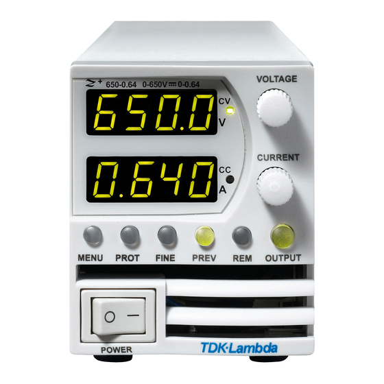
CHAPTER 4: FRONT/REAR PANEL CONTROLS AND CONNECTORS 4.1 Introduction The Z Power Supply series has a full set of controls, indicators and connectors that allow the user to set up and operate the unit. Before starting to operate the unit, please read the following sections for an explanation of the functions, controls and connector terminals. - Page 46 Control/Indicator Description Section AC Power Switch AC ON/OFF control 4 digit 7-segment LED display. Normally displays the output current. Current display In preview mode, the display indicates the program setting of output current. 4 digit 7-segment LED display. Normally displays the output voltage. Voltage Display In preview mode, the display indicates the program setting of output voltage.
-
Page 47: Rear Panel Connectors
4.3 Rear Panel Connectors Refer to Fig.4-2 and Table 4-2 for description of the Rear Panel connectors. Fig. 4-2: Rear panel connections Connection Description Section AC Input Connector IEC320-16 TYPE CONNECTOR DC output Plug for DC output. Analog Control and Connector for remote analog interface. - Page 48 WARNING: Terminals 7, 9 and 12 of J1 are connected internally to the negative sense(-S) potential of the power supply. Do not attempt to bias any of these terminals relative to the negative sense. Use the Isolated Programming interface option to allow control from a programming source at a different potential relative to the power supply negative.
-
Page 49: J1 Connector Terminal And Function
4.3.1 J1 Connector Terminal and Function Control and monitoring signals are referenced to the negative sense potential (-S). Connector Technical Information: • Connector type: 43024-1208, MOLEX. • Receptacle type: 43025-1208, MOLEX. • Contact pins: 43030-0002, MOLEX. • Hand tool: 63819-0000, MOLEX. •... -
Page 50: J3 Connector Terminal And Function
4.3.2 J3 Connector Terminal and Function Control and monitoring signals are isolated from the power supply output. Connector Technical Information • Connector type: 43650-0801, MOLEX. • Receptacle type: 43645-0800, MOLEX. • Contact pins: 43030-0002, MOLEX. • Hand tool: 63819-0000, MOLEX. •... -
Page 51: Front Panel Display Messages
4.4 Front Panel Display Messages Table 4-5 shows the various messages that will be shown on the display in different operating modes. Display Text Text Description Display Text Text Description Abor ABORT ONCE ONCE ADDRESS OT AUTO (RESTART) ATO O bAD BAUD RATE R... -
Page 52: Navigating The Main Menu
4.5 Navigating the Main Menu 4.5.1 Introduction The Main Menu consists of three levels: Subsystem, Function and Parameter. To enter the Menu press the Menu button. The Menu LED illuminates and the display shows the Subsystem Menu. Navigate by rotating the Voltage encoder to scroll through the Subsystem list (first level). Repeat these actions to navigate the Functions list (second level). -
Page 53: Exiting The Main Menu
4.5.2 Exiting the Main Menu There are three ways to exit from Main Menu: 1. Press MENU button twice. MENU LED turns OFF. Display shows present status of power supply. 2. Press and hold MENU button 3sec. MENU LED turns OFF. Display shows present status of power supply. -
Page 54: Exiting The Communication Menu
4.6.2 Exiting the Communication Menu There are three ways to exit from REM menu: 1. Press REM button. 2. No action for 15sec. REM LED turns OFF. Display shows present status of power supply. 4.7 Navigating the Protection Menu 4.7.1 Introduction The Protection Menu consists of two levels: Function and Parameter. -
Page 55: Chapter 5: Local Operation
CHAPTER 5: LOCAL OPERATION 5.1 Introduction This Chapter describes the operating modes that do not require programming and monitoring the power supply via its serial communication ports. USB or RS232/RS485 or by remote analog signals. Ensure that the REM LED on the front panel is Off, (indicating Local mode). If the REM LED is On, press the front panel REM button to change the operating mode to local. -
Page 56: Automatic Crossover
5.2.3 Automatic Crossover When the power supply operates in Constant Voltage mode, while the load current is increased to greater than the current limit setting, the power supply will automatically switch to Constant Current mode. If the load is decreased to less than the current limit setting, the power supply will automatically switch back to Constant Voltage mode. -
Page 57: Alarms And Protective Functions
5.3 Alarms and Protective Functions 5.3.1 Introduction There are several conditions that cause alarm (RED LED blinks). All alarms affect the output. When an alarm occurs, the respective fault will appear on the display and the alarm LED illuminates. It is possible that more than one fault (alarm) may be triggered but only the first will be shown on the display. -
Page 58: Resetting The Ovp Circuit
5.3.2.2 Resetting the OVP Circuit To reset the OVP circuit after activation: 1. Reduce the power supply Output Voltage setting below the OVP set level. 2. Ensure that the load and the sense wiring is connected properly. 3. Four methods to reset the OVP circuit. •... -
Page 59: Setting The Foldback Protection
5.3.4.1 Setting the Foldback Protection The Foldback can be set when the power supply output is Enabled (On) or Disabled (Off ). 1. Press PROT button. PROT (GREEN) LED illuminates. The ”O” message appears on the Voltage display. 2. Rotate Voltage encoder until ”FOD” message appears on Voltage display. 3. -
Page 60: Series Operation
5.4 Series Operation Power supplies of the same model can be connected in series to obtain increased output voltage. Split connection of the power supplies gives positive and negative output voltage. WARNING When power supplies are connected in series, and the load or one of the output terminals is grounded, no point may be at a greater potential of +/- 650VDC from ground. -
Page 61: Series Connection For Positive And Negative Output Voltage
5.4.2 Series Connection for Positive and Negative Output Voltage In this mode, two units are configured as positive and negative output. Set the current limit of each power supply to the maximum that the load can handle without damage. It is recommended that diodes be connected in parallel with each unit output to prevent reverse voltage during start-up or in case one of the units shuts down. -
Page 62: Parallel Operation
5.5 Parallel Operation 5.5.1 Introduction Up to six units of the same Voltage and Current rating can be connected in parallel to provide up to six times the output current capability. One of the units operates as a master and the remaining units are slaves. -
Page 63: Slave Unit Set Up
5.5.2.2 Slave Unit Set Up When Slave mode is selected the power supply enters Current programming mode via external Voltage. Voltage and Current programming setting values are set to 105% of range. During operation the slave units operate as a controlled current source following the master output current. It is recommended that the power system is designed so that each unit supplies up to 95% of its current rating. - Page 64 Fig.5-5: Parallel operation with remote sensing CAUTION: Make sure that the connection between - Vo terminals is reliable to avoid disconnection during operation. Disconnection may cause damage to the power supply. NOTE: With local sensing it is important to minimize the wire length and resistance. Also the positive and negative wire resistance should be as close as possible to each other to achieve current balance between power supplies.
-
Page 65: Advanced Parallel Operation
5.5.3 Advanced Parallel Operation In Advanced Parallel operation the master unit displays the total current of all units connected in Parallel. The slave units display ”ON SE”. The master and slave units operate in a Daisy-Chain connection configuration. For further details about Daisy-chain connection refer to section 5.6. In the Advanced Parallel mode, the total current is programmed and reported by the master unit. -
Page 66: Daisy-Chain Connection
5.6 Daisy-Chain Connection It is possible to configure a multiple power supply system to shut down all units when a fault condition occurs in one of the units. When the fault is removed, the system recovers according to a preset state: Safe start mode or Automatic restart. Set signal ”SO”... -
Page 67: External Shut Off Function
5.7.1 External Shut Off Function SO signal serves as Output Shut Off . It is an optically isolated signal from the power supply output. Connection to the signal is made via pin J3-5 (Shut Off ) and pin J3-7 (IFC_COM). The SO pin accepts a 2.5V to 15V signal or Open-Short contact to disable or enable the power supply output. -
Page 68: Auxiliary Programmed Function Pin 1 And Pin 2
Front Panel ILC Power Supply ILC Input Display Alarm LED Setting Output OFF - Default Open or Short Voltage/Current Open Blinking Short Voltage/Current Table 5-5: Interlock functions and settings CAUTION: To prevent possible damage to the unit, do not connect any of the Enable /Disable inputs to the positive or negative output potential. -
Page 69: Power Supply Ok Signal
5.7.4 Power Supply OK Signal PS_OK signal indicates fault condition in the power supply. It is a TTL signal output at J3-2, referenced to IFC_COM at J3-7 (Isolated Interface Common). When a fault condition occurs, PS_OK level is low, with maximum sink current of 1mA. When no fault condition occurs, PS_OK level is high with maximum source current of 2mA. -
Page 70: Parameter Setting Memory
5.9 Parameter Setting Memory Power Supply has four memory configuration modes: Subsystem Function Parameter Display Display Display Description Level Level Level SAVE SAE 1…4 1...4 Save setting in non violate memory RECALL REC 1…4 1...4 Recall setting in non violate memory Memory MEMo Reset setting... -
Page 71: Save <1
5.9.4 Save <1..4> This command saves the present state of the power supply to a specified location in memory (refer to Table 5-7). Up to 4 states can be stored. Storage locations 1 through 4 are in nonvolatile memory. Save Front panel setting: 1. - Page 72 Parameter Factory Default Resetting Last setting Save & Recall Output Status Voltage Set-point Current Set-point Fold Back mode Over Voltage Protection Under Voltage Level/ OFF (UVL) OFF (UVL) Protection mode Under Voltage Level/ Protection level Auto Start Mode SAFE SAFE Control pin 1 Control pin 2 Input Trigger Source...
-
Page 73: Chapter 6: Remote Analog Programming
CHAPTER 6: REMOTE ANALOG PROGRAMMING 6.1 Introduction The Rear Panel connector J1 allows the user to program the power supply output voltage and current limit with an analog device. J1 also provides monitoring signals for output voltage and output current. The programming range and monitoring signals range can be selected between 0-5V or 0-10V using the Front Panel Menu Subsystem Level. -
Page 74: Remote Voltage Programming Of Output Voltage And Current
6.4 Remote Voltage Programming of Output Voltage and Current Remote Programming settings are as follows: 1. For Voltage Analog Programming wiring refer to Fig.6-1. 2. Short pins J1-1 to J1-7. 3. Press MENU button. MENU (GREEN) LED illuminates. ”Set” message appears on Voltage display. 4. -
Page 75: Remote Resistor Programming Of Output Voltage And Output Current
6.5 Remote Resistor Programming of Output Voltage and Output Current For resistive programming, internal current sources, for output voltage and/or output current control, supply 1mA current through external programming resistors connected between J1-6 and J1-12 and between J1-5 and J1-1, J1-7 & J1-11. The voltage across the programming resistors is used as a programming voltage for the power supply. -
Page 76: Programming Monitoring Of Output Voltage (V_Mon) And Current (I_Mon)
NOTES: In Remote analog mode: the output voltage cannot be set by the Voltage encoder. The output voltage limit is set to 5% over the model-rated maximum value. The output Current limit is set by the Current encoder to 5% over the model-rated maximum value. The power supply will operate within the extended range, however it is not recommended to operate the power supply over its voltage and current rating and performance is not guaranteed. -
Page 77: Chapter 7: Serial Rs232/Rs485 And Usb Interface
CHAPTER 7: Serial RS232/RS485 and USB Interface 7.1 Introduction This chapter describes the set-up, operation, commands and communication protocol of Z power supplies via serial communication interfaces: RS232, RS485 or USB. 7.2 Configuration Parameter Function Level Display Display Description Level 45 Interface I Nt... -
Page 78: Baud Rate Setting
7.2.4 Baud Rate Setting Seven optional rates are possible: 1200, 2400, 4800, 9600, 19200, 38400, 57600. 1. Press REM button. The REM LED illuminates. ”I Nt” message appears on the Voltage display. 2. Rotate Voltage encoder until Voltage display shows ”b d”. 3. -
Page 79: Rear Panel Rs232/485 Connector
7.3 Rear Panel RS232/485 Connector The RS232/485 interface is accessible through the Rear panel RS232/485 IN and RS485 OUT connectors. The connectors are 8 contact RJ-45. The IN and OUT connectors are used to connect power supplies in a RS232 or RS485 chain to a controller. Refer to Fig.7-1 for IN/OUT connectors. Shield (Connector enclosure) NC 8... -
Page 80: Connectig Power Supply To Rs232 Or Rs485 Bus
7.4 Connectig Power Supply To RS232 Or RS485 BUS Connect rear panel IN connector to the controller RS232 or RS485 port using a suitable shielded cable. Refer to Figures 7-2, 7-3 and 7-4 for available RS232 and RS485 cables. Socket DB-25 CONNECTOR 8 PIN CONNECTOR REMARKS... -
Page 81: Rear Panel Usb Connector
7.5 Rear Panel USB Connector A standard USB Series B device connector is located on Rear panel for USB control. Refer to Fig.7-5 and Table 7-2. Designator Description VBUS +5 VDC Data - Data + Interface com Fig.7-5: USB Connector Table 7-2: USB connector pin out 7.5.1 USB Getting Started USB Cable (*) -
Page 82: Gen Protocol (Gen Series Communication Language)
NOTES: RS232/485 RS485 RS485 RS485 It is recommended when using ten or more power supplies in Daisy-chain system to connect 120Ω resistive termination at the last unit’s RS-485 out connector RS485 120Ω, 0.5W between TXD+ and TXD-. 120 OHM 120Ω, 0.5W between RXD+ and RXD-. L=0.5m typ. -
Page 83: Gen Command Set Description
4. Global Commands 5. Auxiliary Commands 6. Status Commands 7.8.3 Identification Commands Returns the power supply model identification as an ASCII string: Default: ”TDK-Lambda,ZX-Y” (one comma, no spaces) IDN? X = rated output voltage Y = rated output current REV? Returns the software version as an ASCII string. -
Page 84: Initialization Commands
7.8.4 Initialization Commands Command Description ADR n ADR is followed by address which can be 1 to 31 and is used to access the power supply . Clear status. Sets FEVE and SEVE registers to zero. Reset command. Brings the power supply to a safe and known state: Output voltage: zero, Remote: non-latched remote, Output current: zero,... - Page 85 Command Description Turns the output to ON or OFF. Recover from Safe-Start, OVP or FLD fault. OUT 1 (or OUT OUT n ON)-Turn On. Returns the output On/Off status string. OUT? ON- output on. OFF- output off. Sets the Foldback protection to ON or OFF. FLD 1 (or FOLD ON) - Arms the Foldback protection.
-
Page 86: Global Output Commands
7.8.6 Global Output Commands General Global commands can be received by all power supplies connected to the BUS, without individual address commands. All power supplies will execute the command immediately. There is no acknowledgment back to the PC when using global commands. A delay must be set of 20msec after each global command. - Page 87 Model Minimum (A) Maximum (A) Model Minimum (A) Maximum (A) 160-1.3 0.000 1.300 160-2.6 0.000 2.600 320-0.65 0.000 0.650 320-1.3 0.000 1.300 650-0.32 0.000 0.320 650-0.64 0.000 0.640 Table 7-6: Z200 models Current programming range Table 7-7: Z400 models Current programming range NOTE: The power supply can accept values higher by 5% than the table values, however it is not recommended to program the power supply over the rated values.
-
Page 88: Auxiliary Commands
7.8.7 Auxiliary Commands Sets SO polarity ”SO 1/ON” –Positive (default), ”SO 0/OFF”-Negative SOP? Returns the SO polarity Remote Interlock (Inhibit) enable. ”RIE 1/ON”-Enable, ”RIE 0/OFF”-Disable” RIE? Returns Interlock enable status. ”ON” –interlock enable, ”OFF”-interlock disable. Factory reset command. This command cover *RST command and additional settings. Sets factory FRST 5-7. -
Page 89: Serial Communication Test Set-Up
7.9 Serial Communication Test Set-Up Basic set-up to test serial communication operation. 1. Equipment: PC with Windows Hyper Terminal, private edition, software installed, Z power supply, RS232 cable. 2. PC set-up: 2.1 Open Hyper Terminal.......New Connection. 2.2 Enter a name 2.3 Connect to........Direct to Com1 or Com 2 2.4 Configure port properties: Bits per second ..9600... -
Page 90: Checksum
7.10.4 Checksum The user may optionally add a checksum to the end of the command. The checksum is ”$” followed by two hex characters. If a command or a query has checksum, the response will also have one. There is no CR between the command string and the ”$” sign. 7.10.5 SCPI Requirements The power supply conforms to the following SCPI requirements: 1. -
Page 91: Data Formats
7.10.8 Data Formats Data Formats Description Digits with an implied decimal point assumed at the right of the least-significant digit. <NR1> Examples: 256 <NR2> Digits with an explicit decimal point. Example: .0253 <NR3> Digits with an explicit decimal point and an exponent. Example: 2.73E+2 <NRf>... - Page 92 Identification query. Returns an identification string in the following format: ‘Manufacturer, Model, Serial number, Firmware level’ . Meaning and Type Identification System Interface Query Syntax *IDN? Field Information TDK-Lambda Manufacturer Model Returned Parameters <Vrating>-<Irating> Model ratings 25B1234 Serial number, typically 7 alpha-numeric characters 3.0-C1 Revisions, <Main firmware>–<LAN/IEEE firmware> Example TDK-Lambda,Z20-30,25B1234, 1.0-C1...
- Page 93 *OPC Operation Complete command. Sets the Operation Complete bit in the Standard Event Status Register if all commands and queries are completed. Meaning and Type Operation Complete Device Status Command Syntax *OPC Parameters None *OPC? Operation Complete query. Returns ASCII ‘1’ as soon as all commands and queries are completed. Meaning and Type Operation Complete Device Status...
- Page 94 *RCL n Restores the power supply to a state previously stored in memory by *SAV command. Refer to Table 5-7. Command Syntax *RCL <NR1> Parameters 1 to 4 Exmple *RCL 3 *RST This command resets the power supply to a defined state as shown in Table 5-7. *RST also forces an ABORt command.
- Page 95 *STB? Status Byte query. Returns the contents of the Status Byte Register. Meaning and Type Status Byte Device Status Query Syntax *STB? Returned Parameters <NR1> (Register binary value) Bit Position Condition OPER QUES (RQS) Bit Weight ESB = Event status byte summary; MAV = Message available MSS = Master status summary;...
-
Page 96: Scpi Subsystem Commands
7.12 SCPI Subsystem Commands Subsystem commands are specific to power supply functions. They can be a single command or a group of commands. Groups are comprised of commands that extend one or more levels below the root. Commands followed by a question mark (?) take only the query form. Except as noted in the syntax descriptions, all other commands take both the command and query form. - Page 97 OUTPut:PROTection:FOLDback Foldback mode is used to disable the output when a transition is made between the operation modes. The power supply will turn off the output after a specified delay if the power supply makes transition into CV mode or into CC mode. This feature is particularly useful for protecting current or voltage sensitive loads.
- Page 98 OUTPut:TTLTrg:MODE Sets the operation of the Trigger Out signal to either OFF, Function Strobe or Trigger mode. Programming Mode NONE, FIX: • In TRIG mode, trigger is generated when output status changes. • In Function Strobe mode, an output pulse is generated automatically any time an output parameter such as output, voltage or current is programmed.
-
Page 99: Instrument Subsystem
7.12.2 Instrument Subsystem The subsystem programs one or more power supplies. <NR1> from 1 to 31. INSTrument:COUPle SCPI Command Syntax INSTrument:COUPle <CRD> GEN Command Syntax None Parameters ALL|NONE INSTrument:NSELect SCPI Command Syntax INSTrument:NSELect <NRf> GEN Command Syntax ADR n (single address) Examples INSTrument:NSELect 6 Query Syntax... - Page 100 NOTE: VOLT:MODE LIST and WAVE is an implied ABORT command. WAVE mode cannot be programmed simultaneously for both Voltage and Current. Only the last sent command can be accepted as WAVE. Previous mode reverts to NONE. VOLTage:PROTection:LEVel Sets the OVP level. The OVP setting range is given in Table 7-9. The number of characters after OVP is up to 12.
-
Page 101: Current Subsystem
VOLTage:PROTection:LOW Sets the under voltage protection (UVP) level of the power supply. SCPI Command Syntax [SOURce]:VOLTage:PROTection:LOW <NRf+> GEN Command Syntax UVL < NRf+> , UVP < NRf+> Default Suffix *RST Value Examples VOLT:PROT:LOW 2.5 VOLT:PROT:LOW MAX [SOURce]:VOLTage:PROTection:LOW [:LEVel]? Query Syntax VOLT:PROT:LOW? MIN;... -
Page 102: Measure Subsystem
CURRent:MODE This command selects FIX, LIST, WAVE subsystems control over the power supply output current. SCPI Command Syntax [SOURce]:CURRent:MODE <CRD> GEN Command Syntax None Parameters NONE | FIXed | LIST | WAVE *RST Value NONE Examples CURR:MODE LIST CURR:MODE FIX Query Syntax [SOURce]:CURRent:MODE? Returned Parameters... -
Page 103: Display Subsystem
MEASure:VOLTage? Reads the measured output voltage. Returns a 5 digit string. SCPI Command Syntax MEASure:VOLTage? GEN Command Syntax Parameters None Default Suffix Returned Parameters <NR3> MEASure:POWer? Reads the measured output power. Returns a 5 digit string. SCPI Command Syntax MEASure:POWer? GEN Command Syntax Parameters None... -
Page 104: Initiate Subsystem
7.12.7 INITiate Subsystem INITiate Enables the trigger subsystem. If a trigger circuit is not enabled, all trigger commands are ignored. SCPI Command Syntax INITiate[:IMMediate] GEN Command Syntax None Parameters None Examples INIT:IMM Query Syntax None INITiate:CONTinuous • INIT:CONT 0 - Enables the trigger subsystem only for a single trigger action. The subsystem must be enabled prior to each subsequent trigger action. - Page 105 LIST:CURRent Specifies the output current points in a list. The current points are given in the command parameters, which are separated by commas. SCPI Command Syntax [SOURce]:LIST:CURRent <NRf+> {,<NRf+>} Default Suffix Examples LIST:CURR 2.5,3.0,3.5 LIST:CURR MAX,2.5,MIN up to 12 parameters Query Syntax LIST:CURRent? Returned Parameters...
-
Page 106: Status Subsystem
LIST:VOLTage Specifies the output voltage points in a list. The voltage points are given in the command parameters, which are separated by commas. SCPI Command Syntax [SOURce]:LIST:VOLTage <NRf+> {,<NRf+>} Default Suffix Examples LIST:VOLT 2.0,2.5,3.0 LIST:VOLT MAX,2.5,MIN up to 12 parameters Query Syntax LIST:VOLT? Returned Parameters... - Page 107 STATus:OPERation:ENABle Sets the value of the Enable register. This register is a mask for enabling specific bits from the Condition register to the Event register. SCPI Command Syntax STATus:OPERation:ENABle <NRf> GEN Command Syntax SENA nnnn, SENA? Parameters 0…7FFF Returned Parameters <NR1>...
-
Page 108: System Subsystem
7.12.10 SYSTem Subsystem SYSTem:ERRor:ENABle Enables Error messages. SCPI Command Syntax SYSTem:ERRor:ENABle GEN Command Syntax None Parameters None Returned Parameters None SYSTem:ERRor? Returns the next error number and corresponding error message in the power supply error queue. Works as FIFO. When no error exists 0, ”No error” is returned. SCPI Command Syntax SYSTem:ERRor? GEN Command Syntax... -
Page 109: Trigger Subsystem
SYSTem:DATE? SCPI Command Syntax SYSTem:DATE? GEN Command Syntax DATE? Query Syntax SYSTem:DATE? Returned Parameters <CRD> yyyy/mm/dd SYSTem:PON:TIME? Time measured from first power On. SCPI Command Syntax SYSTem:PON:TIME? Parameters Minute Example 6534 Returned Parameters <NR1> 7.12.11 TRIGger Subsystem NOTE: The Trigger subsystem must be enabled from the Initiate subsystem or no triggering action will occur. TRIGger When the Trigger subsystem is enabled, TRIG generates an immediate trigger signal that bypasses selected TRIG:DEL. -
Page 110: Wave Subsystem
TRIGger:SOURce Selects the power supply input trigger source as follows: • BUS (*TRG & TRIG) and Front Panel • EXT Mainframe backplane Trigger IN PIN SCPI Command Syntax TRIGger[:STARt]:SOURce <CRD> GEN Command Syntax None Parameters BUS | EXTernal *RST Value EXTernal Examples TRIG: SOUR BUS... -
Page 111: Global Subsystem
WAVE:STEP • WAVE:STEP AUTO - When triggered, creates waveforms consecutively, until the wave is completed. • WAVE:STEP ONCE - When triggered, it executes one step from the list. SCPI Command Syntax [SOURce]WAVE:STEP <CRD> Example WAVE:STEP AUTO Query Syntax [SOURce]:WAVE:STEP? Returned Parameters AUTO | ONCE WAVE:STORe Stores Voltage or Current, Time, STEP parameter and counter values to specific location in the... -
Page 112: Command Summary
Global Commands List Result From Command Name Description SCPI Format GEN Format Supply Enable all Outputs Output On to last V GLOBal:OUTPut:STATe 1|ON GOUT 1 None & I levels Disable all Outputs Turn outputs Off to GLOBal:OUTPut:STATe 0|OFF GOUT 0 None zero V &... -
Page 113: Subsystem Commands
Subsystem Commands SCPI Command Description GEN Command ABORt Aborts the triggered action <NC> DISPlay [:WINDow]:STATe <bool> Display ON/OFF <NC> [:WINDow]:FLASh <bool> Display Flash <NC> GLOBal :CURRent :[AMPLitude] <NRf+> Set the output current for all power supplies :VOLTage :[AMPLitude] <NRf+> Set the output voltage for all power supplies :OUTPut:STATe <bool>... - Page 114 :RELay {1|2} [:STATe] <bool> Set control pins status REL{1|2}[?] :MODE? Returns the operation mode CV/CC/OFF MODE? [SOURce] :CURRent [:LEVel] [:IMMediate] [:AMPLitude] <NRf+> [:AMPLitude] <NRf+> Set the output current PC[?] :TRIGger <NRf+> Set the triggered output current <NC> :MODE NONE|FIX|LIST|WAVE Select arbitrary trigger control mode <NC>...
- Page 115 STATus :OPERation [:EVENt]? Returns the value of the Event register SEVE? :CONDition Returns the value of the Condition register STAT? :ENABle <NRf> Enables specific bits in the Event register SENA[?] :QUEStionable [:EVENt]? Returns the value of the Event register FEVE? :CONDition Returns the value of the Condition register FLT?
-
Page 116: Chapter 8: Advanced Functions
CHAPTER 8: ADVANCED FUNCTIONS 8.1 Introduction This chapter describes the advanced functions of output programmable modes. The are three programmable modes: FIX, WAVE and LIST. The user can program the output transient state. The programmable modes are synchronized by input trigger (refer to section 8.5.1). According to the selected mode, the power supply activates the output trigger on J3-3 (refer to section 8.5.2). -
Page 117: List Mode
8.3 LIST Mode Output change value in step determined by parameters in the LIST subsystem via input trigger. Refer to section 7.12.8 Fig.8-3: Simplified Models of LIST Mode 0.01sec Trig Initated INIT:IMM (Wait Trigger) Trigger Event 0.02s TRIG:DEL 0.02 (Step Started) DWELL 0.05s 0.06s... -
Page 118: Wave Mode
8.4 WAVE Mode Output change value in slope determined by parameters in the WAVE subsystem via input trigger. Refer to section 7.12.12. Fig.8-5: Simplified Models of Trigger in WAVE Mode 0.01sec Trig Initated INIT:IMM (Wait Trigger) Trigger Event 0.02s TRIG:DEL 0.02 (Step Started) TIME 0.03s... -
Page 119: Trigger
8.5 Trigger Subsystem Display Function Level Display Parameter Level Display Description Level Initialization INIT init INIT (Refer to command INIT) iniT TRIG TriG ready for trigger. refer to command Continue ConT INIT:CONT BUS (via Software Trigger Bs refer to command or front Panel), IN (input tr. -
Page 120: Output Trigger
8.5.2 Output Trigger Rear panel connector J3-3 (Refer to section 4.3.2). There are three output trigger modes: Programming Mode NONE, FIX: • OFF – No Trigger out. • In TRIG mode, trigger is generated when output status changes. • In Function Strobe mode, an output pulse is generated automatically any time an output parameter such as output, voltage or current is programmed. -
Page 121: Wave Execution Via Front Panel
8.6.3 Wave Execution via Front Panel 1. Load stored data MENU -> ”ROG” -> ”OAD” -> 2 2. Set Trigger IN source ( BUS for Command or Front Panel and EXT via Rear Panel J3.2 pin) MENU -> ”TR iG” -> ”TR. I n” -> ”BS” 3. -
Page 122: Chapter 9: Status, Fault And Srq Registers
CHAPTER 9: STATUS, FAULT AND SRQ REGISTERS 9.1 General This section describes various status errors (faults) and SRQ register structures. The registers can be read or set via the RS232/485/USB commands. Refer to Fig.9-1 for the Status and Fault Registers Diagram. Fig.9-1: Status and Fault Registers Diagrams (SCPI) -
Page 123: Power Supply Status Structure
9.2 Power Supply Status Structure Status and Fault Register shows the status register structure of the power supply. The Standard Event, Status Byte, and Service Request Enable registers and the Output Queue perform standard functions as defined in the IEEE 488.2 Standard Digital Interface for Programmable Instrumentation. The Operation Status and Questionable Status registers implement status functions specific to the power supply. -
Page 124: Status Register
9.3.2 Status Register The status register sets a bit when status changes (Refer to Table 9-2). The bit is cleared when the condition is removed. Bit Number Decimal Value Bit Symbol Description Set high if Constant Voltage Operation Set high if Constant Current Operation No fault Trigger wait Auto Start Enabled... -
Page 125: Standard Event Status Group
9.6 Standard Event Status Group 9.6.1 Register Functions This group consists of an Event register and an Enable register that are programmed by COMMON commands. The Standard Event register latches events relating to interface communication status. It is a read-only register that is cleared when read. The Standard Event Enable register functions similarly to the Enable registers of the Operation and Questionable status groups. -
Page 126: Status Byte Register
9.6.3 Status Byte Register This register summarizes the information from all other status groups as defined in the IEEE 488.2 Standard Digital Interface for Programmable Instrumentation standard. The register can be read either by a serial poll or by *STB?. Both methods return the same data, except for bit 6. Sending *STB? return MSS in bit 6, while polling returns RQS in bit 6. -
Page 127: Output Queue
9.6.5 Output Queue The Output Queue is a first-in, first-out (FIFO) data register that stores power supply-to-controller messages until the controller reads them. Whenever the queue holds one or more bytes, it sets the MAV bit (4) of the Status Byte register. If too many unread error messages are accumulated in the queue, a system error message is generated. - Page 128 Error Error Description Error Event Number ”No Error” No Error Reported -100 ”Command Error” Unit Receives Command With Unspecified Error. -101 ”Invalid Character” A Character Was Received That Is Not: A-Z, A-Z, 0-9, ?, *, :, ;, Period, Space, CR, LF. IEEE Receives Command Parameter With Wrong Type Of Data.
-
Page 129: Chapter 10: Isolated Analog Programming Option
CHAPTER 10: ISOLATED ANALOG PROGRAMMING OPTION 10.1 Introduction Isolated Analog Programming is an internal option card for analog programming of the Z Power Supply series. The option is factory installed and cannot be obtained with GPIB (IEEE) Interface. Output Voltage and Current Limit can be programmed and readback through optically isolated signals which are isolated from all other ground references in the power supply. -
Page 130: Isolated Programming & Monitoring Connector
10.3 Isolated Programming & Monitoring Connector Refer to Table 10-1 for detailed description of the Rear Panel Isolated Programming & Monitoring connector. To provide the lowest noise performance, it is recommended to use shielded-twisted pair wiring. Refer to Fig.10-1 for description of the connector. Isolated programming plug P/N: MC1.5/8-ST-3.81, Phoenix. -
Page 131: Setup And Operating Instructions
10.4 Setup and Operating Instructions CAUTION: To prevent damage to the unit, do not program the output voltage and current to higher than the power supply rating. 10.4.1 Setting Up Power Supply for 0-5/0-10V Isolated Programming and Monitoring Perform the following procedure to configure the power supply: 1. -
Page 132: Chapter 11: Maintenance
CHAPTER 11: MAINTENANCE 11.1 Introduction This chapter provides information about maintenance, calibration and troubleshooting. 11.2 Units Under Warranty Units requiring repair during the warranty period should be returned to a TDK Lambda authorized service facility. Refer to the address listings on the back cover of this manual. Unauthorized repairs performed by other than the authorized service facilities may void the warranty. -
Page 133: Fuse Rating
SYMPTOM CHECK ACTION REF. Check continuity, replace Is the AC power cord defective? if necessary. No output. All displays and indicators are blank. Is the AC input voltage Check input AC voltage. within range? Connect to appropriate voltage source. Output is present momentarily Does the AC source voltage sag Check input AC voltage. - Page 134 11.1 Einleitung Dieses Kapitel liefert Informationen über Wartung, Kalibrierung und Fehlersuche. 11.2 Reparaturen während der Garantie Sollte ein Gerät innerhalb der Garantiezeit ausfallen, so dürfen Reparaturen nur durch Lambda oder autorisierte Servicestellen durchgeführt werden. Die Adressen finden Sie am Ende dieses Handbuches.
- Page 135 Symptom Prüfung Tätigkeit Ref. Ist das Netzkabel defekt? Falls erforderlich, Netzkabel ersetzen. Keine Ausgangsspannung. Displays und Anzeigen sind Ist die Netzspannung innerhalb Netzspannung prüfen, Gerät an passende dunkel. des Eingangsbereiches? Versorgungsspannung anschließen. Ausgangsspannung liegt Bricht die Netzspannung kurzfristig an, schaltet aber Netzspannung prüfen, Gerät an passende zusammen, wenn am Ausgang sofort wieder ab.
-
Page 136: User Manual Index
USER MANUAL INDEX ac cables humidity 20, 24, 28, 32 safe start 61, 64, 73, 90, 101 ac fail hyper terminal safety accessories SCPI 82, 83, 94 acknowledge series operation address 82, 87, 89, 104 Identification Commands 88, 97 shield 17, 43, 44, 45 auto restart 61, 90, 101... - Page 137 NOTES...
- Page 138 NOTES...
- Page 139 NOTES...
- Page 140 Fax: +81-3-5201-7287 www.tdk-lambda.com CHINA TDK-Lambda UK Ltd. Kingsley Avenue Ilfracombe, Devon Shanghai Branch of Wuxi TDK-Lambda Electronic Co. Ltd. 28F, Xingyuan Technology Building No.418, Guiping Road, EX 34 8ES United Kingdom Tel: +44-1271-856666 Fax: +44-1271-864894 Shanghai, China 200233 E-mail: powersolutions@uk.tdk-lambda.com Tel: +86-21-6485-0777 Fax: +86-21-6485-0666 www.
Need help?
Do you have a question about the Z160-1.3 and is the answer not in the manual?
Questions and answers