Advertisement
Quick Links
C8051F530A D
1. Relevant Devices
The C8051F530 Development Kit is intended as a development platform for microcontrollers in the C8051F53x/
52x MCU family. Code developed on the C8051F530 can be easily ported to the other members of this MCU
family.
2. Kit Contents
The C8051F530 Development Kit contains the following items:
C8051F530A Target Board
C8051Fxxx Development Kit Quick-Start Guide
AC to DC Power Adapter
USB Debug Adapter (USB to Debug Interface)
USB Cable
The development kit target board contains two C8051F530 microcontrollers that can communicate through an LIN
network. One of the C8051F530 (U2) can also be connected to a CP2102 USB to UART bridge and directly
connected to two analog signals and a Voltage Reference Signal Input.
3. Hardware Setup Using a USB Debug Adapter
The target board is connected to a PC running the Silicon Laboratories IDE via the USB Debug Adapter as shown
in Figure 1.
1. Connect the USB Debug Adapter to one of the DEBUG connectors on the target board (HDR1 or HDR2)
with the 10-pin ribbon cable. The recommended connection is to the HDR2 (connected to U2) as this
microcontroller can be connected to the CP2102 USB to UART bridge.
2. Verify that shorting blocks are installed on J13 and J14 to supply power to the target devices.
3. Connect one end of the USB cable to the USB connector on the USB Debug Adapter.
4. Connect the other end of the USB cable to a USB Port on the PC.
5. Connect the ac/dc power adapter to power jack P5 on the target board.
PC
Rev. 0.4 11/14
EVELOPMENT
USB
Cable
Figure 1. Hardware Setup using a USB Debug Adapter
Copyright © 2014 by Silicon Laboratories
C 8 0 5 1 F 5 3 x / 5 2 x
K
U
I T
SER
USB Debug Adapter
HDR2
Reset_A
'
G
S
UIDE
Target Board
HDR1
Reset_B
AC/DC
Adapter
C8051F53x/52x
Advertisement

Subscribe to Our Youtube Channel
Related Manuals for Silicon Laboratories C8051F53 Series


Summary of Contents for Silicon Laboratories C8051F53 Series
- Page 1 Voltage Reference Signal Input. 3. Hardware Setup Using a USB Debug Adapter The target board is connected to a PC running the Silicon Laboratories IDE via the USB Debug Adapter as shown in Figure 1.
-
Page 2: Software Setup
C8051F53x/52x Notes: Use the Reset button in the IDE to reset the target when connected using a USB Debug Adapter. Remove power from the target board and the USB Debug Adapter before connecting or disconnecting the ribbon cable from the target board. Connecting or disconnecting the cable when the devices have power can damage the device and/or the USB Debug Adapter. - Page 3 C8051F53x/52x In the Part Selection step of the wizard, select from the list of installed parts only the parts to be used during development. Choosing parts and families in this step affects the displayed or filtered parts in the later device selection menus.
-
Page 4: Install Drivers
Laboratories... option in the Programs and Features window. 4.4. Configuration Wizard 2 The Configuration Wizard 2 is a code generation tool for all of the Silicon Laboratories devices. Code is generated through the use of dialog boxes for each of the device's peripherals. -
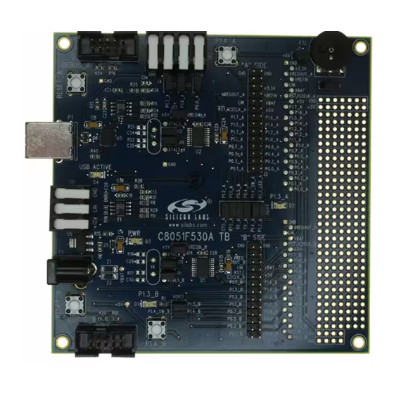
Page 5: Target Board
Connects VREFIN to U2 P0.0_A Analog input connector HDR4 Connector block for serial port connection, Green LED, and push-button Silicon Laboratories CP2102 USB-to-UART Bridge USB connector to serial interface (CP2102) USB ACTIVE Red USB Active LED (D4) (CP2102) LIN transceiver C8051F530A “A”... - Page 6 Pin 1 P1.4_A GND CH2 CH1 VRefin DEBUG_A “A” Side USB ACTIVE Pin 1 P1.3_A SILICON LABORATORIES Pin 1 C8051F530A TB “B” Side HDR3 P1.3_B Pin 1 DEBUG_B P1.4_B Pin 1 Pin 1 Figure 4.
- Page 7 C8051F53x/52x 5.2. System Clock Sources The C8051F530A device installed on the target board features a calibrated programmable internal oscillator that is enabled as the system clock source on reset. After reset, the internal oscillator operates at a frequency of 191.4 kHz (±0.5%) by default but may be configured by software to operate at other frequencies. Therefore, in many applications, an external oscillator is not required.
- Page 8 C8051F53x/52x 5.4. Expansion I/O Connectors (J1, J2) The two Expansion I/O connectors J1 (26 pins) and J2 (28 pins) provide access to all signal pins of the C8051F530A devices. Pins for V , GND, 5 V, Reset, Vbat, LIN, 3.3 V, and VREFIN are also available. A small through-hole prototyping area is also provided.
- Page 9 C8051F53x/52x 5.6. USB to Serial Connector (P1, HDR4) A USB-to-Serial bridge interface is provided. A B-type USB connector (P1), a CP2102, and related circuits are provided to facilitate the serial connection between a PC and the U2 A-Side C8051F530A microcontroller on the target board.
- Page 10 C8051F53x/52x 5.9. LIN Connectivity (TB1) The C8051F530A Target Board has two C8051F530A devices (U1 and U2) and two LIN transceivers (T1 and T2) to provide LIN connectivity on the target board. These devices can also be interfaced to another LIN bus using the TB1 terminal block.
- Page 11 C8051F53x/52x 6. Schematics Rev. 0.4...
- Page 12 C8051F53x/52x Rev. 0.4...
- Page 13 C8051F53x/52x Rev. 0.4...
-
Page 14: Document Change List
C8051F53x/52x OCUMENT HANGE Revision 0.2 to Revision 0.3 Updated for C8051F530A TB. Added "LIN Connectivity (TB1)‚" on page 10. Revision 0.3 to Revision 0.4 Updated "Software Setup‚" on page 2. Rev. 0.4... - Page 15 The products must not be used within any Life Support System without the specific written consent of Silicon Laboratories. A "Life Support System" is any product or system intended to support or sustain life and/or health, which, if it fails, can be reasonably expected to result in significant personal injury or death.
- Page 16 Mouser Electronics Authorized Distributor Click to View Pricing, Inventory, Delivery & Lifecycle Information: Silicon Laboratories C8051F530ADK...
Need help?
Do you have a question about the C8051F53 Series and is the answer not in the manual?
Questions and answers