Table of Contents
Advertisement
Quick Links
Advertisement
Table of Contents

Related Manuals for HIKVISION DS-K2600-G Series


Summary of Contents for HIKVISION DS-K2600-G Series
- Page 1 DS-K2600-G Series Access Controller User Manual UD05678B...
- Page 2 This Manual is subject to domestic and international copyright protection. Hangzhou Hikvision Digital Technology Co., Ltd. (“Hikvision”) reserves all rights to this manual. This manual cannot be reproduced, changed, translated, or distributed, partially or wholly, by any means, without the prior written permission of Hikvision.
- Page 3 Access Controller·User Manual Regulatory Information FCC Information Please take attention that changes or modification not expressly approved by the party responsible for compliance could void the user’s authority to operate the equipment. FCC compliance: This equipment has been tested and found to comply with the limits for a Class B digital device, pursuant to part 15 of the FCC Rules.
- Page 4 Access Controller·User Manual Preventive and Cautionary Tips Before connecting and operating your device, please be advised of the following tips: • Ensure unit is installed in a well-ventilated, dust-free environment. • Keep all liquids away from the device. • Ensure environmental conditions meet factory specifications. •...
- Page 5 Access Controller·User Manual Safety Instruction These instructions are intended to ensure that user can use the product correctly to avoid danger or property loss. The precaution measure is divided into Warnings and Cautions: Warnings: Neglecting any of the warnings may cause serious injury or death. Cautions: Neglecting any of the cautions may cause injury or equipment damage.
- Page 6 Access Controller·User Manual Please use a soft and dry cloth when clean inside and outside surfaces of the device cover, do not use alkaline detergents. Please keep all wrappers after unpack them for future use. In case of any failure occurred, you need to return the device to the factory with the original wrapper.
-
Page 7: Table Of Contents
Access Controller·User Manual Table of Contents Chapter 1 Product Description ....................1 Overview ..........................1 Main Features ........................1 Chapter 2 Component Description ................... 3 Chapter 3 Terminal Connection ....................5 Terminal Description ......................5 3.1.1 DS-K2601-G-GTerminal Description ................. 5 3.1.2 DS-K2602-GTerminal Description .................. - Page 8 Access Controller·User Manual Activating via SADP Software ..................... 25 Activating via Client Software .................... 26 Chapter 7 Client Operation ....................29 Function Module ........................ 29 User Registration and Login ....................32 System Configuration ......................33 Access Control Management ..................... 34 7.4.1 Adding Access Control Device ..................
- Page 9 Access Controller·User Manual Searching Access Control Event ..................98 7.10 Access Control Event Configuration ................... 99 7.10.1 Access Control Event Linkage ..................99 7.10.2 Access Control Alarm Input Linkage ................. 101 7.10.3 Event Card Linkage ....................101 7.10.4 Cross-Device Linkage ....................103 7.11 Door Status Management ....................
-
Page 10: Chapter 1 Product Description
Access Controller·User Manual Chapter 1 Product Description 1.1 Overview DS-K2600-G is a powerful and stable access controller, using the logical architecture design. DS-K2600-G is designed with TCP/IP network interface and its signal processed with special encryption and can be run offline. Anti-tampering function is also supported. 1.2 Main Features ... - Page 11 Access Controller·User Manual The access controller has backup battery design, watchdog design and tamper-proof function Data can be permanently saved after the access controller is powered off. Supports I/O linkage, and event linkage Supports Ehome protocol, and inter-network communication ...
-
Page 12: Chapter 2 Component Description
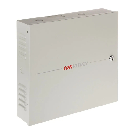
Access Controller·User Manual Chapter 2 Component Description Take DS-K2604-G as an example, the component schematic diagram is shown below. Component Description DS-K2601-G DS-K2602-G DS-K2604-G Alarm Relay Output Status (NC/NO) Network Data Indicator RS-485 Communication Indicator Network Status Indicator Door Relay Output Status (NC/NO) Choice Battery Charging Indicator Power Indicator Charging Completing Indicator... - Page 13 Access Controller·User Manual Component Description Running Indicator Hardware Initialization and Normal Working Choice Main board dial-up switch/ Reserved...
-
Page 14: Chapter 3 Terminal Connection
Access Controller·User Manual Chapter 3 Terminal Connection 3.1 Terminal Description 3.1.1 DS-K2601-G Terminal Description DS-K2601-G Terminal descriptions are as follows: DS-K2601-G Grounding Lock Power +12V Power Output of the Lock Grounding Card Reader Power +12V Power Output of the Head Read Grounding Wiegand Head Read Data Input Data0 Wiegand Head Read Data Input Data1... - Page 15 Access Controller·User Manual DS-K2601-G Indicator of Card Reader Control Output (Valid Card Output) Grounding Wiegand Head Read Data Input Data0 Wiegand Head Read Data Input Data1 Card Reader Buzzer Control Output Wiegand Card Reader 1 Indicator of Card Reader Control Output (Invalid Card Output) Indicator of Card Reader Control Output (Valid Card Output)
-
Page 16: Ds-K2602-Gterminal Description
Access Controller·User Manual DS-K2601-G RS 485D+ RS 485D- Reserved NO/NC1 Alarm Relay 1 Output (Dry Contact) COM1 Alarm Output NO/NC2 Alarm Relay 2 Output (Dry Contact) COM2 Event Alarm Input 2 Event Input Grounding Event Alarm Input 1 3.1.2 DS-K2602-G Terminal Description DS-K2602-G Terminal descriptions are as follows: DS-K2602-G Grounding... - Page 17 Access Controller·User Manual DS-K2602-G +12V Power Output of the Head Read Grounding Wiegand Head Read Data Input Data0 Wiegand Head Read Data Input Data1 Wiegand Card Reader Card Reader Buzzer Control Output Indicator of Card Reader Control Output (Invalid Card Output) Indicator of Card Reader Control Output (Valid Card Output) Grounding...
- Page 18 Access Controller·User Manual DS-K2602-G E-Lock1 Door 1 Door Relay Input (Dry Contact) E-Lock2 Door 2 Door Relay Input (Dry Contact) Door 1 Magnetic Detector Input Door Magnetics Signal Grounding Detector Door 2 Magnetic Detector Input Door 1 Door Button Input Door Button Signal Grounding Door 2 Door Button Input...
-
Page 19: Ds-K2604-G Terminal Description
Access Controller·User Manual DS-K2602-G NO/N Alarm Relay 4 Output (Dry Contact) COM4 Event Alarm Input 4 Grounding Event Alarm Input3 Event Input Event Alarm Input 2 Grounding Event Alarm Input 1 3.1.3 DS-K2604-G Terminal Description DS-K2604-G Terminal descriptions are as follows: DS-K2604-G Power Supply Grounding... - Page 20 Access Controller·User Manual DS-K2604-G Grounding Wiegand Card Reader Data Input Data0 Wiegand Card Reader Data Input Data1 Wiegand Card Buzzer of Card Reader Control Output Reader 4 Cresset of Card Reader Control Output (Invalid Card Output) Cresset of Card Reader Control Output (Valid Card Output) Grounding Wiegand Card Reader Data Input Data0...
- Page 21 Access Controller·User Manual DS-K2604-G E-Lock 1 Door 1 Door Relay Input (Dry Contact) E-Lock 2 Door 2 Door Relay Input (Dry Contact) E-Lock 3 Door 3 Door Relay Input (Dry Contact) E-Lock 4 Door 4 Door Relay Input (Dry Contact) Door 1 Magnetic Detector Input Signal Grounding Door 2 Magnetic Detector Input...
- Page 22 Access Controller·User Manual DS-K2604-G COM4 Event Alarm Input 8 Grounding Event Alarm Input 7 Event Alarm Input 6 Grounding Event Alarm Input 5 Event Input Event Alarm Input 4 Grounding Event Alarm Input3 Event Alarm Input 2 Grounding Event Alarm Input 1 Notes: ...
-
Page 23: Chapter 4 Card Reader Installation
Access Controller·User Manual Chapter 4 Card Reader Installation 4.1 External Terminal 4.1.1 DS-K2601-G External Terminals 4.1.2 DS-K2602-G External Terminals 4.1.3 DS-K2604-G External Terminals... -
Page 24: Card Reader Installation
Access Controller·User Manual 4.2 Card Reader Installation 4.2.1 The Connection of Wiegand Card Reader Note: You must connect the OK/ERR/BZ, if using access controller to control the LED and buzzer of the Wiegand card reader. -
Page 25: Rs485 Card Reader Connection
Access Controller·User Manual 4.2.2 RS485 Card Reader Connection Note: If the card reader is installed too far away from the access controller, you can use an external power supply. -
Page 26: Installing E-Lock
Access Controller·User Manual 4.3 Installing E-Lock 4.3.1 Installation of Cathode Lock 4.3.2 Installation of Anode Lock... -
Page 27: Connecting The External Alarm Device
Access Controller·User Manual 4.4 Connecting the External Alarm Device 4.5 Door Button Wiring Diagram... -
Page 28: The Connection Of Magnetics Detection
Access Controller·User Manual 4.6 The Connection of Magnetics Detection 4.7 Connecting Power Supply... -
Page 29: Arming Region Input Terminal
Access Controller·User Manual 4.8 Arming Region Input Terminal 4.8.1 Connecting Normally Open Detector 4.8.2 Connecting Normally Closed Detector... -
Page 30: Fire Alarm Module Wiring
Access Controller·User Manual 4.9 Fire Alarm Module Wiring... -
Page 31: Chapter 5 Settings
Access Controller·User Manual Chapter 5 Settings 5.1 Initializing the Hardware Option 1: Steps: 1. Remove the jumper cap from the Normal terminal. 2. Disconnect the power and restart the access controller. The controller buzzer buzzes a long beep. 3. When the beep stopped, plug the jumper cap back to Normal. Option 2: Steps: 1. -
Page 32: Alarm Relay Output Status
Access Controller·User Manual 5.2.2 Alarm Relay Output Status Alarm Relay Output Normally Open: Alarm Relay Output Normally Closed: Work Flow of Software For detailed information, please see the user manual of the client software. Refer to the following work flow:... - Page 33 Access Controller·User Manual...
-
Page 34: Chapter 6 Activating The Access Control Terminal
Access Controller·User Manual Chapter 6 Activating the Access Control Terminal Purpose: You are required to activate the terminal first before using it. Activation via SADP, and Activation via client software are supported. The default values of the control terminal are as follows. ... -
Page 35: Activating Via Client Software
Access Controller·User Manual segment with your computer by either modifying the IP address manually or checking the checkbox of Enable DHCP. 6. Input the password and click the Modify button to activate your IP address modification. 6.2 Activating via Client Software The client software is versatile video management software for multiple kinds of devices. - Page 36 Access Controller·User Manual 2. Click the Device Management to enter the Device Management interface. 3. Check the device status from the device list, and select an inactive device. 4. Click the Activate button to pop up the Activation interface. 5. In the pop-up window, create a password in the password field, and confirm the password. STRONG PASSWORD RECOMMENDED–...
- Page 37 Access Controller·User Manual 6. Click OK button to start activation. 7. Click the Modify Netinfor button to pop up the Network Parameter Modification interface. 8. Change the device IP address to the same network segment with your computer by either modifying the IP address manually.
-
Page 38: Chapter 7 Client Operation
Access Controller·User Manual Chapter 7 Client Operation You can set and operate the access control devices via the client software. This chapter will introduce the access control device related operations in the client software. For integrated operations, refer to User Manual of iVMS-4200 Client Software. 7.1 Function Module Control Panel of iVMS-4200: Menu Bar:... - Page 39 Access Controller·User Manual 1024*768 Display the window at size of 1024*768 pixels. 1280*1024 Display the window at size of 1280*1024 pixels. 1440*900 Display the window at size of 1440*900 pixels. 1680*1050 Display the window at size of 1680*1050 pixels. Maximize Display the window in maximum mode.
- Page 40 Access Controller·User Manual For the first time running the software, you can click on the control panel to select the modules to display on the Operation and Control area of the control pane. Steps: 1. Click to pop up the following dialog. 2.
-
Page 41: User Registration And Login
Access Controller·User Manual The Time and Attendance module provides setting the attendance rule for the employees and generating the reports. The Security Control Panel module provides operations such as arming, disarming, bypass, group bypass, and so on for both the partitions and zones. The Real-time Alarm module provides displaying the real-time alarm of security control panel, acknowledging alarms, and searching the history alarms. -
Page 42: System Configuration
Access Controller·User Manual A user name cannot contain any of the following characters: / \ : * ? “ < > |. And the length of the password cannot be less than 6 characters. For your privacy, we strongly recommend changing the password to something of your own choosing (using a minimum of 8 characters, including upper case letters, lower case letters, numbers, and special characters) in order to increase the security of your product. -
Page 43: Access Control Management
Access Controller·User Manual Steps: 1. Click Tool – System Configuration. 2. In the System Configuration window, check the Auto-synchronize Access Control Event checkbox. 3. Set the synchronization time. The client will auto-synchronize the missed access control event to the client at the set time. 7.4 Access Control Management Purpose: The Access Control module is applicable to access control devices and video intercom. -
Page 44: Adding Access Control Device
Access Controller·User Manual Notes: Once the scene is configured, you cannot change it later. When you select Non-Residence mode, you cannot configure the Attendance Rule when adding person. The Access Control module is composed of the following sub modules. Managing the organizations, persons, and assigning Person and Card cards to persons. - Page 45 Access Controller·User Manual Note: After adding the device, you should check the device arming status in Tool – Device Arming Control. If the device is not armed, you should arm it, or you will not receive the real-time events via the client software. For details about device arming control, refer 7.12 Arming Control. Creating Password Purpose: For some devices, you are required to create the password to activate them before they can be...
- Page 46 Access Controller·User Manual resetting the password monthly or weekly can better protect your product. 5. (Optional) Enable Hik-Connect service when activating the device if the device supports. 1) Check Enable Hik-Connect checkbox to pop up the Note dialog. 2) Create a verification code. 3) Confirm the verification code.
- Page 47 Access Controller·User Manual Adding Online Device Purpose: The active online devices in the same local subnet with the client software will be displayed on the Online Device area. You can click the Refresh Every 60s button to refresh the information of the online devices.
- Page 48 Access Controller·User Manual minimum of 8 characters, including upper case letters, lower case letters, numbers, and special characters) in order to increase the security of your product. And we recommend you reset your password regularly, especially in the high security system, resetting the password monthly or weekly can better protect your product.
- Page 49 Access Controller·User Manual Adding Devices by IP or Domain Name Steps: 1. Click Add to open the device adding dialog box. 2. Select IP/Domain as the adding mode. 3. Input the required information. Nickname: Edit a name for the device as you want. Address: Input the device’s IP address or domain name.
- Page 50 Access Controller·User Manual Adding Devices by IP Segment Steps: 1. Click Add to open the device adding dialog box. 2. Select IP Segment as the adding mode. 3. Input the required information. Start IP: Input a start IP address. End IP: Input an end IP address in the same network segment with the start IP. Port: Input the device port No..
- Page 51 Access Controller·User Manual list. Adding Devices by Hik-Connect Domain Purpose: You can add the devices connected via Hik-Connect by inputting the Hik-Connect account and password. Before you start: Add the devices to Hik-Connect account via iVMS-4200, iVMS-4500 Mobile Client, or Hik-Connect first. For details about adding the devices to Hik-Connect account via iVMS-4200, refer to the User Manual of iVMS-4200 Client Software.
- Page 52 Access Controller·User Manual 5. Optionally, check the Export to Group checkbox to create a group by the device name. You can import all the channels of the device to the corresponding group by default. 6. Click Add to add the device. Add Devices in Batch Steps: 1.
- Page 53 Access Controller·User Manual 6. Check the checkbox(es) to select the device as desired. 7. Input the user name and password for the devices to be added. 8. Optionally, check the Export to Group checkbox to create a group by the device name. You can import all the channels of the device to the corresponding group by default.
- Page 54 Access Controller·User Manual Nickname: Edit a name for the device as you want. Account: Input the account name registered on EHome protocol. 4. Optionally, check the Export to Group checkbox to create a group by the device name. You can import all the channels of the device to the corresponding group by default. Note: iVMS-4200 also provides a method to add the offline devices.
- Page 55 Access Controller·User Manual 3) Click Add. When the offline device comes online, the software will connect it automatically. 5. Click Add to add the device. Adding Devices by IP Server Steps: 1. Click Add to open the device adding dialog box. 2.
- Page 56 Access Controller·User Manual When the offline device comes online, the software will connect it automatically. 5. Click Add to add the device. Adding Devices by HiDDNS Steps: 1. Click Add to open the device adding dialog box. 2. Select HiDDNS as the adding mode. 3.
- Page 57 Access Controller·User Manual 5. Click Add to add the device. Importing Devices in Batch Purpose: The devices can be added to the software in batch by inputting the device information in the pre-defined CSV file. Steps: 1. Click Add to open the device adding dialog box. 2.
-
Page 58: Viewing Device Status
Access Controller·User Manual The password strength of the device can be checked by the software. For your privacy, we strongly recommend changing the password to something of your own choosing (using a minimum of 8 characters, including upper case letters, lower case letters, numbers, and special characters) in order to increase the security of your product. -
Page 59: Editing Basic Information
Access Controller·User Manual Note: The interface may different from the picture displayed above. Refer to the actual interface when adopting this function. Door Status: The status of the connected door. Host Status: The status of the host, including Storage Battery Power Voltage, Device Power Supply Status, Multi-door Interlocking Status, Anti-passing Back Status, and Host Anti-Tamper Status. -
Page 60: Network Settings
Access Controller·User Manual 4. Edit the device information, including the adding mode, the device name, the device IP address, port No., user name, and the password. 7.4.4 Network Settings Purpose: After adding the access control device, you can set the uploading mode, and set the network center and wireless communication center. - Page 61 Access Controller·User Manual 5. Click Save button to save parameters. Network Center Settings You can set the account for EHome protocol in Network Settings page. Then you can add devices via EHome protocol. Steps: 1. Click the Network Center tab. 2.
-
Page 62: Capture Settings
Access Controller·User Manual 2. Select the APN name as CMNET or UNINET. 3. Input the SIM Card No. 4. Select the center group in the dropdown list. 5. Input the IP address and port No. 6. Select the protocol type as EHome. By default, the port No. for EHome is 7660. 7. -
Page 63: Settings
Access Controller·User Manual 2. Select the resolution of the captured pictures from the dropdown list. Note: The supported resolution types are CIF, QCIF, 4CIF/D1, SVGA, HD720P, VGA, WD1, and AUTO. 3. Select the picture quality as High, Medium, or Low. 4. -
Page 64: Wiegand Settings
Access Controller·User Manual 7.4.7 Wiegand Settings Purpose: You can set the Wiegand channel and the communication mode. Select the device in the device list, and click Modify to pop up the modifying device information window. Click Wiegand-485 Settings tab to enter the Wiegand settings interface. Note: The Wiegand Settings should be supported by the device. -
Page 65: Remote Configuration
Access Controller·User Manual 2. Set the sector ID. 3. Click Save to save the settings. Note: The sector ID ranges from 1 to 100. 7.4.9 Remote Configuration Purpose: In the device list, select the device and click Remote Configuration button to enter the remote configuration interface. - Page 66 Access Controller·User Manual Editing Time Steps: 1. In the Remote Configuration interface, click System -> Time to configure the time zone. 2. (Optional) Check Enable NTP and configure the NTP server address, the NTP port, and the synchronization interval. 3. (Optional) Check Enable DST and configure the DST star time, end time and the bias. 4.
- Page 67 Access Controller·User Manual 2) Click to select the upgrade file. 3) Click Upgrade to start upgrading. Note: Only card readers connected via RS-485 can be upgraded. Managing User Steps: 1. In the Remote Configuration interface, click System -> User. 2. Click Add to add the user (Do not support by the elevator controller.). Or select a user in the user list and click Edit to edit the user.
- Page 68 Access Controller·User Manual Setting Security Steps: 1. Click System -> Security. 2. Select the encryption mode in the dropdown list. You can select Compatible Mode or Encryption Mode. 3. Click Save to save the settings. Configuring Network Parameters Click Network -> General. You can configure the NIC type, the IPv4 address, the subnet mask (IPv4), the default gateway (IPv4), MTU address, MTU, and the device port.
- Page 69 Access Controller·User Manual You can set the center group for uploading the log via the EHome protocol. Steps: Click Network -> Report Strategy. Select a Center Group from the drop-down list. Check the Enable check box. Set the uploading method. You can set the main channel and the backup channel.
- Page 70 Access Controller·User Manual 2. Click to pop up the Zone Settings window. 3. Set the zone name, the detector type, the zone type and the sensitivity. 4. Click Save to save the settings. Or click Copy to… to copy the parameters to other zones. Configuring Relay Parameters Steps: 1.
- Page 71 Access Controller·User Manual 1. In the Remote Configuration interface, click Other -> Access Control Parameters. 2. Select and check the Downstream RS-485 Communication Backup checkbox or the Press Key to Input Card No. checkbox. 3. Click Save to save the settings. Uploading Background Picture Click Other ->...
-
Page 72: Person And Card Management
Access Controller·User Manual You can view the zone information. 2. Check the zone checkbox. 3. Click Arm or Disarm to arm or disarm the zone. 4. (Optional) click Refresh to refresh the zone status. Operating Relay Steps: 1. Click Operation -> Relay. You can view the relay status. -
Page 73: Organization Management
Access Controller·User Manual Click tab to enter the Person and Card Management interface. The interface is divided into two parts: Organization Management and Person Management. Organization You can add, edit, or delete the organization as Management desired. After adding the organization, you can add the Person Management person to the organization and issue card to persons for further management. -
Page 74: Person Management
Access Controller·User Manual The lower-level organizations will be deleted as well if you delete an organization. Make sure there is no person added under the organization, or the organization cannot be deleted. 7.5.2 Person Management After adding the organization, you can add person to the organization and manage the added person such as issuing cards in batch, importing and exporting persons information in batch, etc. - Page 75 Access Controller·User Manual 1. In the Add Person interface, click Details tab. 2. Input the detailed information of the person, including person’s ID type, ID No., country, etc., according to actual needs. Linked Device: You can bind the indoor station to the person. Note: If you select Analog Indoor Station in the Linked Device, the Door Station field will display and you are required to select the door station to communicate with the analog...
- Page 76 Access Controller·User Manual remove it. You can also click << to remove all the selected permissions. 4. Click OK to save the settings. Adding Person (Card) You can add card and issue the card to the person. Steps: 1. In the Add Person interface, click Card tab. 2.
- Page 77 Access Controller·User Manual Visitor Card: The card is assigned for visitors. For the Visitor Card, you can set the Max. Swipe Times. Notes: The Max. Swipe Times should be between 0 and 255. When your swiping card times is more than the configured times, card swiping will be invalid.
- Page 78 Access Controller·User Manual Manually Input: Input the card No. and click Enter to input the card No. 7. Click OK and the card(s) will be issued to the person. 8. (Optional) You can select the added card and click Edit or Delete to edit or delete the card. 9.
- Page 79 Access Controller·User Manual a fingerprint or inputs a fingerprint unsuccessfully, the device will indicate that the fingerprint collecting is over. 3. Click Start button, click to select the fingerprint to start collecting. 4. Lift and rest the corresponding fingerprint on the fingerprint scanner twice to collect the fingerprint to the client.
- Page 80 Access Controller·User Manual 4) Click OK to start exporting. 2. Importing Person: You can import the Excel file with persons information in batch from the local PC 1) click Import Person button in the Person and Card tab. 2) You can click Download Template for Importing Person to download the template first. 3) Input the person information to the downloaded template.
- Page 81 Access Controller·User Manual 3. The added access control device will be displayed. 4. Click to select the device and then click OK to start getting the person information from the device. You can also double click the device name to start getting the person information. Notes: ...
- Page 82 Access Controller·User Manual Issuing Card in Batch You can issue multiple cards for the person with no card issued in batch. Steps: 1. Click Issue Card in Batch button to enter the following dialog. All the added person with no card issued will display in the Person(s) with No Card Issued list. 2.
-
Page 83: Schedule And Template
Access Controller·User Manual 1) Select the Card Enrollment Station type. Note: Currently, the supported card reader types include DS-K1F100-D8, DS-K1F100-M, DS-K1F100-D8E, and DS-K1F180-D8E. 2) Set the parameters about the connected card enrollment station. If the card is M1 card, and if you need to enable the M1 Card Encryption function, you should check Enable checkbox of M1 Card Encryption and click Modify to select the sector. -
Page 84: Week Schedule
Access Controller·User Manual You can manage the schedule of access control permission including Week Schedule, Holiday Schedule, and Template. For permission settings, please refer to Chapter 7.7 Permission Configuration. 7.6.1 Week Schedule Click Week Schedule tab to enter the Week Schedule Management interface. The client defines two kinds of week plan by default: Whole Week Schedule and Blank Schedule, which cannot be deleted and edited. -
Page 85: Holiday Group
Access Controller·User Manual period of time, the configured permission is activated. Note: Up to 8 time periods can be set for each day in the schedule. 5. When the cursor turns to , you can move the selected time bar you just edited. You can also edit the displayed time point to set the accurate time period. -
Page 86: Template
Access Controller·User Manual information. 4. Click Add Holiday icon on the right to add a holiday period to the holiday list and configure the duration of the holiday. Note: Up to 16 holidays can be added to one holiday group. 1) On the period schedule, click and drag to draw the period, which means in that period of time, the configured permission is activated. - Page 87 Access Controller·User Manual There are two pre-defined templates by default: Whole Week Template and Blank Template, which cannot be deleted and edited. Whole Week Template: The card swiping is valid on each day of the week and it has no holiday group schedule.
-
Page 88: Permission Configuration
Access Controller·User Manual 5. Select holiday groups to apply to the schedule. Note: Up to 4 holiday groups can be added. Click to select a holiday group in the list and click Add to add it to the template. You can also click Add Holiday Group to add a new one. -
Page 89: Adding Permission
Access Controller·User Manual 7.7.1 Adding Permission Purpose: You can assign permission for persons to enter/exist the access control points (doors) in this section. Steps: 1. Click Add icon to enter following interface. In the Permission Name field, input the name for the permission as desired. 3. -
Page 90: Applying Permission
Access Controller·User Manual permission to enter/exit the selected door/door station with their linked card(s) or fingerprints. 7. (Optional) after adding the permission, you can click Details to modify it. Or you can select the permission and click Modify to modify. You can select the added permission in the list and click Delete to delete it. -
Page 91: Access Control Parameters
Access Controller·User Manual Note: The advanced functions should be supported by the device. Click icon to enter the following interface. 7.8.1 Access Control Parameters Purpose: After adding the access control device, you can configure its access control point (door)’s parameters, and its card readers’ parameters. Click Access Control Parameters tab to enter the parameters settings interface. - Page 92 Access Controller·User Manual 2. You can editing the following parameters: Door Magnetic: The Door Magnetic is in the status of Remain Closed (excluding special conditions). Exit Button Type: The Exit Button Type is in the status of Remain Open (excluding special conditions).
-
Page 93: Card Reader Authentication
Access Controller·User Manual 2. You can editing the following parameters: Nickname: Edit the card reader name as desired. Enable Card Reader: Select Yes to enable the card reader. OK LED Polarity: Select the OK LED Polarity of the card reader mainboard. Error LED Polarity: Select the Error LED Polarity of the card reader mainboard. - Page 94 Access Controller·User Manual 1. Click Card Reader Authentication tab and select a card reader on the left. 2. Select a card reader authentication mode. The available authentication modes depend on the card reader type: Card and Password: The door can open by both inputting the card password and swiping the card.
-
Page 95: Multiple Authentication
Access Controller·User Manual 4. Repeat the above step to set other time periods. Or you can select a configured day and click Copy to Week button to copy the same settings to the whole week. (Optional) You can click Delete button to delete the selected time period or click Clear button to delete all the configured time periods. - Page 96 Access Controller·User Manual You can manage the cards by group and set the authentication for multiple cards for one access control point (door). Note: Please set the card permission and apply the permission setting to the access control device first. For details, refer to Chapter 7.7 Permission Configuration. Steps: 1.
- Page 97 Access Controller·User Manual 1) In the Card Group Name field, input the name for the group as desired. 2) Click to set the effective time and expiry time of the card group. 3) Check the checkbox(es) to select the card(s) to add the card group. 4) Click OK to save the card group.
-
Page 98: Open Door With First Card
Access Controller·User Manual The Card Swiping Times should be larger than 0 and smaller than the added card quantity in the card group. The upper limit of Card Swiping Times is 16. 6) Click OK to save the settings. 5. -
Page 99: Anti-Passing Back
Access Controller·User Manual Notes: The Remain Open Duration should be between 0 and 1440 minutes. By default, it is 10 minutes. In the First Card Authorization mode, you can access the door when swiping the super card, the duress card or input the duress code without swiping the first card. ... -
Page 100: Cross-Controller Anti-Passing Back
Access Controller·User Manual Steps: 1. Click Anti-passing Back tab to enter the following interface. 2. Select an access control device from the device list on the left. 3. In the First Card Reader field, select the card reader as the beginning of the path. 4. - Page 101 Access Controller·User Manual card according to the configured swiping card route. And only one person could pass the access control point after swiping the card. Click Cross-Controller Anti-passing Back to enter the Cross-Controller Anti-passing Back tab. Setting Route Anti-passing Back Purpose: The route anti-passing back depends on the card swiping route.
- Page 102 Access Controller·User Manual Notes: The displayed card readers in the card reader afterward input field should be in authentication order. Up to 64 controllers with anti-passing back function can be added. Up to 16 card readers afterward can be added for each card reader. ...
-
Page 103: Multi-Door Interlocking
Access Controller·User Manual 3) Set the sector ID. 4) Click Select Device to select a device in the pop-up window for anti-passing back authentication. 5) In the Set Card Reader area, check the checkboxes in the Enable Anti-passing Back column to select the entrance card reader and the exit card reader. 6) Click Save to save the settings. -
Page 104: Authentication Password
Access Controller·User Manual 1. Click Multi-door Interlocking tab to enter the multi-door interlock settings page. 2. Select an access controller from the Controller List. 3. Click Add to pop up the Add Access Control Point to Interlock interface. 4. Select the access control point (door) from the list. Note: Up to four doors can be added in one multi-door interlocking combination. -
Page 105: Custom Wiegand
Access Controller·User Manual All the cards and persons which have been applied to the device will be displayed. Note: For setting and applying the permissions to the device, refer to Chapter 7.7 Permission Configuration. 2. Click the Password field of the card and input the authentication password for the card. Note: The authentication password should contain 4 to 8 digits. - Page 106 Access Controller·User Manual 2. Select a custom wiegand on the left of the interface. 3. Check Enable checkbox to enable the custom wiegand. 4. Set the wiegand name. 5. Select device. 1) Click Select Device. 2) Select the device need to use custom wiegand. 3) Click OK to save the settings.
-
Page 107: Searching Access Control Event
Access Controller·User Manual 4) (Optional) Click to change the rule order. 5) (Optional) Select the rules in the Selected Rule list and click to remove the rule from the list on the right. 6) Click OK to save the settings. 7) In the Custom Wiegand tab, set the rule start bit, length, and the decimal digit. -
Page 108: Access Control Event Configuration
Access Controller·User Manual Steps: 1. Select the source. You can select Client or Device. 2. Enter the search condition (source, event type/card holder name/card No./capture/start & end time). 3. Click Search to get the search results. 4. View the event information in the event list. 5. - Page 109 Access Controller·User Manual Note: The linkage here refers to the linkage of the client software’s own actions. Steps: 1. Click the Access Control Event tab. 2. The added access control devices will display in the Access Control Device panel on the left. Select the access control device, or alarm input, or access control point (door), or card reader to configure the event linkage.
-
Page 110: Access Control Alarm Input Linkage
Access Controller·User Manual Alarm Triggered The image with alarm information pops up when alarm is Pop-up Image triggered. 7.10.2 Access Control Alarm Input Linkage Purpose: The access control alarm inputs can be linked to some actions (e.g., alarm output, host buzzer) when it is triggered. - Page 111 Access Controller·User Manual The linkage here refers to the linkage of the client software’s own actions. Select the access control device from the list on the left. Click Add button to add a new linkage. You can select the event source as Event Linkage or Card Linkage.
-
Page 112: Cross-Device Linkage
Access Controller·User Manual The door status of open, close, remain open, and remain close cannot be triggered at the same time. The target door and the source door cannot be the same one. 3. Click Save button to save and take effect of the parameters. Card Linkage Steps: 1. - Page 113 Access Controller·User Manual Click Add button to add a new client linkage. You can select the event source as Event Linkage or Card Linkage. Event Linkage For the event linkage, the alarm event can be divided into four types: device event, alarm input, door event, and card reader event.
-
Page 114: Door Status Management
Access Controller·User Manual 2. Select the card from the dropdown list and select the access control device as event source. 3. Select the card reader from the table for triggering. 4. Set the linkage target, select the access control device from the dropdown list as the linkage target, and switch the property from to enable this function. -
Page 115: Anti-Control The Access Control Point (Door)
Access Controller·User Manual the name of the selected device. 4. Perform the following steps to import the access control points to the group: 1) Click Import on Group Management interface, and then click the Access Control tab to open the Import Access Control page. Notes: ... - Page 116 Access Controller·User Manual Click icon on the control panel to enter the Status Monitor interface. Steps: 1. Select an access control group on the left. For managing the access control group, refer to Chapter 7.11.1 Access Control Group Management. 2. The access control points of the selected access control group will be displayed on the right. Click icon on the Status Information panel to select a door.
-
Page 117: Status Duration Configuration
Access Controller·User Manual 7.11.3 Status Duration Configuration Purpose: You can schedule weekly time periods for an access control point (door) to remain open or remain closed. In the Door Status module, click button to enter the Status Duration interface. Status Duration Steps: 1. -
Page 118: Real-Time Card Swiping Record
Access Controller·User Manual 3) When the cursor turns to , you can move the selected time bar you just edited. You can also edit the displayed time point to set the accurate time period. When the cursor turns to , you can lengthen or shorten the selected time bar. 3. -
Page 119: Real-Time Access Control Alarm
Access Controller·User Manual The logs of card swiping records of all access control devices will display in real time. You can view the details of the card swiping event, including card No., person name, organization, event time, etc. You can also click the event to view the card holder details, including person No., person name, organization, phone, contact address, etc. -
Page 120: Arming Control
Access Controller·User Manual Steps: All access control alarms will display in the list in real time. You can view the alarm type, alarm time, location, etc. Click to view the alarm on E-map. You can click to view the live view or the captured picture of the triggered camera when the alarm is trigged. - Page 121 Access Controller·User Manual You can arm or disarm the device. After arming the device , the client can receive the alarm information from the device. Steps: 1. Click Tool->Device Arming Control to pop up the Device Arming Control window. 2. Arm the device by checking the corresponding checkbox. Then the alarm information will be auto uploaded to the client software when alarm occurs.
-
Page 122: Appendix A Sound Prompt And Indicator
Access Controller·User Manual Appendix A Sound Prompt and Indicator After the card reader is powered on, LED status indicator will turn blue and blink for 1 time. Then it will turn red and blink for 3 times. At last the buzzer will send out a beep sound indicating the starting up process is completed. -
Page 123: Appendix B Custom Wiegand Rule Descriptions
Access Controller·User Manual Appendix B Custom Wiegand Rule Descriptions Take Wiegand 44 as an example, the setting values in the Custom Wiegand tab are as follows: Custom Wiegand Name: Wiegand 44 Total Length Transformation Rule (Decimal byFormatRule[4]=[1][4][0][0] Digit) Parity Mode XOR Parity Odd Parity Start Bit Length... - Page 124 Access Controller·User Manual available. Depending on the table displayed above, the manufacturer code start bit is 32, length is 8, and decimal digit is 3. It represents that from bit 32, there are 8 bits are manufacturer code. (The length here is calculated by bit.) And the decimal length is 3.
- Page 125 Access Controller·User Manual...
Need help?
Do you have a question about the DS-K2600-G Series and is the answer not in the manual?
Questions and answers