Table of Contents
Advertisement
Advertisement
Table of Contents

Related Manuals for HIKVISION DS-K2604T


Summary of Contents for HIKVISION DS-K2604T
- Page 1 Access Controller Quick Start Guide...
- Page 2 (hereinafter referred to be “Hikvision”). This user manual (hereinafter referred to be “the Manual”) cannot be reproduced, changed, translated, or distributed, partially or wholly, by any means, without the prior written permission of Hikvision. Unless otherwise stipulated, Hikvision does not make any warranties, guarantees or representations, express or implied, regarding to the Manual.
- Page 3 AMONG OTHERS, DAMAGES FOR LOSS OF BUSINESS PROFITS, BUSINESS INTERRUPTION, OR LOSS OF DATA OR DOCUMENTATION, IN CONNECTION WITH THE USE OF THIS PRODUCT, EVEN IF HIKVISION HAS BEEN ADVISED OF THE POSSIBILITY OF SUCH DAMAGES. REGARDING TO THE PRODUCT WITH INTERNET ACCESS, THE USE OF PRODUCT SHALL BE WHOLLY AT YOUR OWN RISKS.
- Page 4 DS-K2600 Series Access Controller Regulatory Information FCC Information Please take attention that changes or modification not expressly approved by the party responsible for compliance could void the user’s authority to operate the equipment. FCC compliance: This equipment has been tested and found to comply with the limits for a Class B digital device, pursuant to part 15 of the FCC Rules.
- Page 5 DS-K2600 Series Access Controller 2. This device must accept any interference received, including interference that may cause undesired operation. EU Conformity Statement This product and - if applicable - the supplied accessories too are marked with "CE" and comply therefore with the applicable harmonized European standards listed under the R&TTE Directive 1999/5/EC, the EMC Directive 2014/30/EU, the LVD Directive 2014/35/EU, the RoHS Directive 2011/65/EU.
- Page 6 DS-K2600 Series Access Controller Preventive and Cautionary Tips Before connecting and operating your device, please be advised of the following tips: • Ensure unit is installed in a well-ventilated, dust-free environment. • Keep all liquids away from the device. • Ensure environmental conditions meet factory specifications.
- Page 7 DS-K2600 Series Access Controller Warnings: Please adopt the power adapter from the legitimate factory which can meet the safety extra low voltage (SELV) standard. Do not install, wiring, or uninstall when the power is still on. To reduce the risk of fire or electrical shock, do not expose this product to rain or moisture.
-
Page 8: Table Of Contents
DS-K2600 Series Access Controller Table of Contents 1 Product Description .................... 3 1.1 Overview .......................... 3 1.2 Main Feature ........................3 2 Appearance ......................5 3 Terminal Connection ................... 7 3.1 Terminals Description ...................... 7 3.1.1 DS-K2601 Terminal Description ................. 7 3.1.2 DS-K2602 Terminal Description ................ - Page 9 DS-K2600 Series Access Controller 4.9 Fire Alarm Module Wiring ..................... 26 5 Settings ......................27 5.1 Initializing the Hardware....................27 5.2 Relay Input NO/NC ......................27 5.2.1 Lock Relay Output ....................27 5.2.2 Alarm Relay Output Status ..................28 6 Activating Device ....................31 6.1 Activation via SADP Software ..................
-
Page 10: Product Description
DS-K2600 Series Access Controller 1 Product Description 1.1 Overview DS-K2600 is a powerful and stable access controller, using the logical architecture design. DS-K2600 is designed with TCP/IP network interface and its signal processed with special encryption and can be run offline. Anti-tampering function is also supported. 1.2 Main Feature ... - Page 11 DS-K2600 Series Access Controller swiping records can be stored in the selected server.) and inner-device anti-pass-back function Supports RS485 interface and Wiegand interface for accessing card reader. RS485 interface adopts dual-interface design and supports loop breakpoint detection and redundancy function; Wiegand interface supports W26, W34 and is seamlessly compatible with third-party card reader with Wiegand interface ...
-
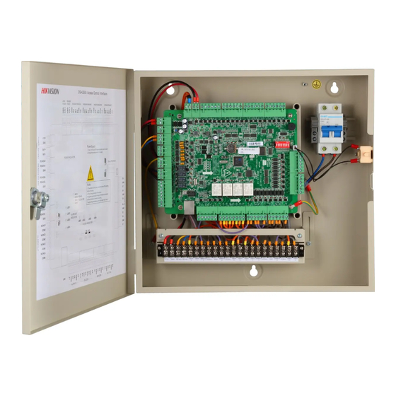
Page 12: Appearance
DS-K2600 Series Access Controller 2 Appearance Take DS-K2604 as an example, the component schematic diagram is shown below. Figure 2-1 DS-K2604 Component Schematic Diagram Table 2-1 DS-K2600 Component Description Component Description DS-K2601 DS-K2602 DS-K2604 Alarm Relay Output Status (NC/NO) Network Data Indicator... - Page 13 DS-K2600 Series Access Controller Component Description RS-485 Communication Indicator Network Status Indicator Door Relay Output Status (NC/NO) Choice Battery Charging Indicator Power Indicator Charging Completing Indicator Running Indicator Hardware Initialization and Normal Working Choice Main board dial-up switch Set the DIP address for the access controller. Available Range: 1 to 63.
-
Page 14: Terminal Connection
DS-K2600 Series Access Controller 3 Terminal Connection 3.1 Terminals Description 3.1.1 DS-K2601 Terminal Description Figure 3-1 DS-K2601 Terminals... - Page 15 DS-K2600 Series Access Controller Table 3-1 DS-K2601 Terminal Description DS-K2601 Grounding Lock Power +12V Power Output of the Lock Grounding Card Reader Power +12V Power Output of the Head Read Grounding Wiegand Head Read Data Input Data0 Wiegand Head Read Data Input Data1 Wiegand Card Card Reader Buzzer Control Output Reader 2...
- Page 16 DS-K2600 Series Access Controller DS-K2601 Input Grounding Door 1 Door Open Button Input Door Open Button Grounding +12V DC12V Cathode Power DC12V Grounding Input BAT+ DC12V Battery Cathode Battery BAT- DC12V Battery Anode Card Reader RS485+ Access 485A+ Card Reader RS485- Access 485A- Grounding 485 Card...
-
Page 17: Ds-K2602 Terminal Description
DS-K2600 Series Access Controller DS-K2601 Event Alarm Input 2 Event Input Grounding Event Alarm Input 1 3.1.2 DS-K2602 Terminal Description Figure 3-2 DS-K2602 Terminal Description... - Page 18 DS-K2600 Series Access Controller Table 3-2 DS-K2602 Terminal Description DS-K2602 Grounding Power for E-Lock +12V Power Output of the Lock Grounding Power for Card Reader +12V Power Output of the Head Read Grounding Wiegand Head Read Data Input Data0 Wiegand Head Read Data Input Data1 Wiegand Card Card Reader Buzzer Control Output Reader 4...
- Page 19 DS-K2600 Series Access Controller DS-K2602 Wiegand Head Read Data Input Data1 Card Reader Buzzer Control Output Indicator of Card Reader Control Output (Invalid Card Output) Indicator of Card Reader Control Output (Valid Card Output) Arming Region Access Terminal 1 Grounding Arming Region Access Terminal 2 Arming Region Arming Region Access Terminal 3...
- Page 20 DS-K2600 Series Access Controller DS-K2602 485B+ Card Reader RS485- 485B- Grounding Uplink RS485+Communication 485C+ Uplink RS485-Communication 485C- Grounding RS-485 Interface 485D+ Reserved 485D- NO/N Alarm Relay 1 Output (Dry Contact) COM1 NO/N Alarm Relay 2 Output (Dry Contact) COM2 Alarm Output NO/N Alarm Relay 3 Output (Dry Contact) COM3...
-
Page 21: Ds-K2604 Terminal Description
DS-K2600 Series Access Controller 3.1.3 DS-K2604 Terminal Description Figure 3-3 DS-K2604 Access Controller Terminals Table 3-3 DS-K2604 Port Description DS-K2604 Grounding Power Supply of Power Supply of E-Lock Output +12V E-Lock Power Grounding Supply of +12V Power Supply of Card Reader Output Card Reader Grounding Wiegand... - Page 22 DS-K2600 Series Access Controller DS-K2604 Wiegand Card Reader Data Input Data1 Buzzer of Card Reader Control Output Cresset of Card Reader Control Output (Invalid Card Output) Cresset of Card Reader Control Output (Valid Card Output) Grounding Wiegand Card Reader Data Input Data0 Wiegand Card Reader Data Input Data1 Wiegand Buzzer of Card Reader Control Output...
- Page 23 DS-K2600 Series Access Controller DS-K2604 Arming Region Access Terminal 1 Grounding Arming Region Access Terminal 2 Arming Region Input Arming Region Access Terminal 3 Grounding Arming Region Access Terminal 4 E-Lock 1 Door 1 Door Relay Input (Dry Contact) E-Lock 2 Door 2 Door Relay Input (Dry Contact) E-Lock 3 Door 3 Door Relay Input (Dry Contact)
- Page 24 DS-K2600 Series Access Controller DS-K2604 BAT- DC12V Battery Anode Card Reader RS485A+ 485A+ RS 485A- Card Reader RS485A- Card Reader Grounding RS485 RS 485B+ Card Reader RS485B+ RS 485B- Card Reader RS485B- Grounding RS 485C+ Uplink RS485+Communication RS 485C- Uplink RS485-Communication Grounding Access Controller...
- Page 25 DS-K2600 Series Access Controller DS-K2604 Event Alarm Input3 Event Alarm Input 2 Grounding Event Alarm Input 1 Notes: The Alarm input hardware interface is normally open by default. So only the normally open signal is allowed. It can be linked to the buzzer of the card reader and access controller, and the alarm relay output and door relay open and close.
-
Page 26: Card Reader Installation
DS-K2600 Series Access Controller 4 Card Reader Installation 4.1 External Terminal 4.1.1 DS-K2601 External Terminals Figure 4-1 DS-K2601 External Terminals 4.1.2 DS-K2602 External Terminals Figure 4-2 DS-K2602 External Terminals 4.1.3 DS-K2604 External Terminals Figure 4-3 DS-K2604 External Terminals... -
Page 27: Card Reader Installation
DS-K2600 Series Access Controller 4.2 Card Reader Installation 4.2.4 The Connection of Wiegand Card Reader Figure 4-4 Wiring diagram of Wiegand card reader Note: You must connect the OK/ERR/BZ, if using access controller to control the LED and buzzer of the Wiegand card reader. -
Page 28: Rs485 Card Reader Connection
DS-K2600 Series Access Controller 4.2.5 RS485 Card Reader Connection Figure 4-5 Wiring diagram of RS485 Note: If the card reader is installed too far away from the access controller, you can use an external power supply. -
Page 29: Installing E-Lock
DS-K2600 Series Access Controller 4.3 Installing E-Lock 4.3.1 Installation of Cathode Lock Figure 4-6 Wiring diagram of cathode lock 4.3.2 Installation of Anode Lock Figure 4-7 Wiring diagram of anode lock... -
Page 30: Connecting The External Alarm Device
DS-K2600 Series Access Controller 4.4 Connecting the External Alarm Device Figure 4-8 External Alarm Device Connection 4.5 Door Button Wiring Diagram Figure 4-9 Power Button Connection... -
Page 31: The Connection Of Magnetics Detection
DS-K2600 Series Access Controller 4.6 The Connection of Magnetics Detection Figure 4-10 Magnetics Connection 4.7 Connecting Power Supply Figure 4-11 Power Supply Connection... -
Page 32: Arming Region Input Terminal
DS-K2600 Series Access Controller 4.8 Arming Region Input Terminal 4.8.1 Connecting Normally Open Detector Figure 4-12 Normally Open Status 4.8.2 Connecting Normally Closed Detector Figure 4-13 Normally Closed Status... -
Page 33: Fire Alarm Module Wiring
DS-K2600 Series Access Controller 4.9 Fire Alarm Module Wiring Figure 4-14 Fire Alarm Module Wiring... -
Page 34: Settings
DS-K2600 Series Access Controller 5 Settings 5.1 Initializing the Hardware Option 1: Steps: 1. Remove the jumper cap from the Normal terminal. 2. Disconnect the power and restart the access controller. The controller buzzer buzzes a long beep. 3. When the beep stopped, plug the jumper cap back to Normal. 4. -
Page 35: Alarm Relay Output Status
DS-K2600 Series Access Controller Figure 5-2 Normally Open Status Lock Relay Normally Closed Status Figure 5-3 Normally Closed Status 5.2.2 Alarm Relay Output Status Alarm Relay Output Normally Open Figure 5-4 Alarm Relay Output Normally Open... - Page 36 DS-K2600 Series Access Controller Alarm Relay Output Normally Closed Figure 5-5 Normally Closed Status Work Flow of Software For detailed information, please see the user manual of the client software. Refer to the following work flow:...
- Page 37 DS-K2600 Series Access Controller Figure 5-6 Software Client Work Flow...
-
Page 38: Activating Device
DS-K2600 Series Access Controller 6 Activating Device Purpose: You are required to activate the control panel first before you can use the control panel. Activation via SADP, and Activation via client software are supported. 6.1 Activation via SADP Software SADP software is used for detecting the online device, activating the device, and resetting the password. - Page 39 DS-K2600 Series Access Controller STRONG PASSWORD RECOMMENDED– We highly recommend you create a strong password of your own choosing (using a minimum of 8 characters, including upper case letters, lower case letters, numbers, and special characters) in order to increase the security of your product. And we recommend you reset your password regularly, especially in the high security system, resetting the password monthly or weekly can better protect your product.
-
Page 40: Activation Via Client Software
DS-K2600 Series Access Controller 6.2 Activation via Client Software The client software is versatile video management software for multiple kinds of devices. Get the client software from the supplied disk, and install the software according to the prompts. Follow the steps to activate the control panel. Steps: Run the client software and the control panel of the software pops up, as shown in the figure below. - Page 41 DS-K2600 Series Access Controller Click the Activate button to pop up the Activation interface. In the pop-up window, create a password in the password field, and confirm the password. STRONG PASSWORD RECOMMENDED– We highly recommend you create a strong password of your own choosing (using a minimum of 8 characters, including upper case letters, lower case letters, numbers, and special characters) in order to increase the security of your product.
-
Page 42: Appendix Adip Switch Description
DS-K2600 Series Access Controller Appendix A DIP Switch Description There are two groups of DIP switches on the master lane control board. Take the 8-bit DIP switch as an example; No.1 to No 8 is from the low bit to the high bit. When the switch is towards ON, it means the switch is enabled, otherwise, the switch is off. - Page 43 DS-K2600 Series Access Controller UD05848B-B...
Need help?
Do you have a question about the DS-K2604T and is the answer not in the manual?
Questions and answers