
Subscribe to Our Youtube Channel
Related Manuals for Kramer TP-133


Summary of Contents for Kramer TP-133
-
Page 1: User Manual
K R A ME R E LE CT R O N IC S L T D . USER MANUAL MODELS: TP-133 Automatic PC/Audio Data Line Transmitter TP-134 Automatic PC/Audio/Data Line Receiver P/N: 2900-300012 Rev 4... -
Page 3: Table Of Contents
Setting the Skew and Equalization Automatically Technical Specifications Figures F igure 1: TP-133 Automatic PC/Audio/Data Line Transmitter Front and Rear Panels F igure 2: TP-134 Automatic PC/Audio/Data Line Transmitter Front and Rear Panels F igure 3: Connecting the TP-133/TP-134 PC/Audio/Data Line Transmitter/Receiver System... -
Page 4: Introduction
Introduction Welcome to Kramer Electronics! Since 1981, Kramer Electronics has been providing a world of unique, creative, and affordable solutions to the vast range of problems that confront the video, audio, presentation, and broadcasting professional on a daily basis. In recent years, we have redesigned and upgraded... -
Page 5: Getting Started
Avoid interference from neighboring electrical appliances that may adversely influence signal quality • Position your Kramer TP-133 and TP-134 away from moisture, excessive sunlight and dust Shielded Twisted Pair/Unshielded Twisted Pair We recommend that you use Shielded Twisted Pair (STP) cable, and stress that the compliance to electromagnetic interference was tested using STP cable. -
Page 6: Overview
The distance using non −Kramer CAT 5, CAT 6, and CAT 7 cables may not reach these ranges. Use only shielded cable where both ends of the shield are soldered to ground •... -
Page 7: Defining The Tp-133/Tp-134 Line Transmitter And Receiver
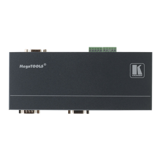
Balanced and unbalanced stereo audio • RS-232 data The TP-133 encodes the signals and transmits them over TP cable to a TP-134 receiver. RS-232 commands and data flow bidirectionally, allowing status requests and control of a destination unit. Figure 1 defines the front and rear panels of the TP-133. -
Page 8: Defining The Tp-134 Automatic Pc/Audio/Data Line Receiver
Receiver The TP-134 is a high-performance receiver that accepts the computer graphics/audio/RS-232 data from the Kramer TP-133 via TP cabling at its RJ-45 LINE IN input. The TP-134 outputs a computer graphics signal, an unbalanced stereo audio signal, a balanced stereo audio signal and RS 232 data signal. -
Page 9: F Igure 2: Tp-134 Automatic Pc/Audio/Data Line Transmitter Front And Rear Panels
AUDIO OUT 3.5mm Mini Connect to an unbalanced, stereo audio acceptor Jack LINE IN RJ-45 Connector Connect to the LINE OUT RJ-45 connector on the TP-133 (see Section 5.2 PC VIDEO OUT 15-pin Connect to a computer graphics video acceptor... -
Page 10: Connecting The Tp-133/Tp-134
Connecting the TP-133/TP-134 After connecting your TP-133 and TP-134, connect the power adapters. Figure 3: Connecting the TP-133/TP-134 PC/Audio/Data Line Transmitter/Receiver System TP-133/TP-134 - Connecting the TP-133/TP-134... - Page 11 To connect the TP-133 and the TP-134 to create a TP transmitter and receiver system as illustrated in Figure 3 1. On the TP-133, connect: A computer graphics video source (for example, the graphics card on a laptop) to the PC IN 15-pin HD connector (M) An unbalanced, stereo audio source (for example, the audio source on ...
-
Page 12: Connecting The Audio Output To Balanced And Unbalanced Audio Equipment
Connecting the Audio Output to Balanced and Unbalanced Audio Equipment Figure 4 illustrates how to connect the TP-133/TP-134 balanced audio output to a balanced acceptor. Figure 4: Connecting to a Balanced Acceptor Figure 5 illustrates how to connect the TP-133/TP-134 balanced audio output to an unbalanced acceptor. -
Page 13: Adjusting Rgb And Compensation On The Tp-134
TP-134 The skew and equalization can be set either manually or automatically. After connecting the TP-133/TP-134 to the power adapters (assuming that the twisted pair link is working), the LINK and POWER LEDs on the front of the TP-134 light green. - Page 14 The effect is seen in the green vertical bars shifting to the left or right. 5. To move to the blue setting, press and hold the COLOR button for three seconds. TP-133/TP-134 - Adjusting RGB and Compensation on the TP-134...
-
Page 15: Setting The Skew And Equalization Automatically
Setting the Skew and Equalization Automatically To adjust the color skew on the TP-134: • Press and hold the COLOR and SELECT buttons together for three seconds. The color and equalization are set automatically. TP-133/TP-134 - Adjusting RGB and Compensation on the TP-134... -
Page 16: Technical Specifications
19.05cm x 8.63cm x 2.44cm (7.5" x 3.4" x 0.96") W, D, H WEIGHT: 0.33kg (0.73lbs.) approx. each ACCESSORIES: Power supply, AD-GF/GF 15−pin Power supply HD (F/F) Gender Changer OPTIONS: RK-T2B 19” rack adapter, Kramer BC-DGKat623 TP-133/TP-134 - Technical Specifications... - Page 17 1. Any product which is not distributed by us or which is not purchased from an authorized Kramer dealer. If you are uncertain as to whether a dealer is authorized, please contact Kramer at one of the agents listed in the Web site www.kramerelectronics.com.
- Page 18 " " P/N: 2900- 300012 Rev: 4...
Need help?
Do you have a question about the TP-133 and is the answer not in the manual?
Questions and answers