Table of Contents
Advertisement
Available languages
Available languages
Quick Links
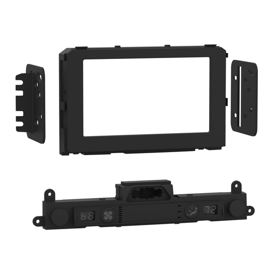
KIT COMPONENTS
• A) Radio trim panel • B) Radio brackets • C) Climate display • D) Wiring harness (not shown)
A
Metra. The World's Best Kits.
®
Kia Sportage
2020-2021
Visit
MetraOnline.com
specific applications
KIT FEATURES
• ISO DDIN radio provision
• Integrated electronics with laser
etched graphics retain the factory
climate control display features.
B
MetraOnline.com
(with auto climate control w/o factory amplifier)
for more detailed information about the product and up-to-date vehicle
• Retains factory steering wheel
controls and back up camera.
• Painted scratch resistant matte black.
C
© COPYRIGHT 2022 METRA ELECTRONICS CORPORATION
95-7298B
I N S TA L L AT I O N I N S T R U C T I O N S
TABLE OF CONTENTS
Dash Disassembly ...............................................2-3
Kit Preparation ...................................................4-6
Kit Assembly ..........................................................7
Axxess Interface Installation ............................ 8-15
WIRING & ANTENNA CONNECTIONS
Wiring Harness: Included with kit
Antenna Adapter: Included with kit
TOOLS REQUIRED
• Panel removal tool • Phillips screwdriver
• Pick tool
Attention!
With the key out of the ignition,
disconnect the negative battery terminal
before installing this product. Ensure that all
installation connections are secure before
cycling the ignition to test this product.
REV. 9/14/22 INST99-7298B
Advertisement
Chapters
Table of Contents

Related Manuals for Metra Electronics 95-7298B


Summary of Contents for Metra Electronics 95-7298B
- Page 1 Ensure that all installation connections are secure before cycling the ignition to test this product. Metra. The World’s Best Kits. MetraOnline.com ® © COPYRIGHT 2022 METRA ELECTRONICS CORPORATION REV. 9/14/22 INST99-7298B...
- Page 2 DASH DISASSEMBLY 1. Unclip and slide the top of the center 3. Unclip the panel above the glove box. console back slightly. (Figure A) Unplug the passenger airbag light, then remove the panel. (Figure C) 2. Unclip and remove the panel on the 4.
- Page 3 DASH DISASSEMBLY (CONT.) 5. Remove (4) Phillips screws securing the 7. Remove (1) Phillips screw securing the radio. Slide the radio out, then unplug lower right side drivers knee bolster. and remove the radio. (Figure E) Unsnap the bolster just enough to access the (1) Phillips screw securing the 6.
- Page 4 KIT PREPARATION Radio Trim Panel Installation To the factory radio trim panel: 2. Snap in the 95-7298B radio trim panel to the factory panel. (Figure A) Continued on the next page (Figure A) 386.257.1187 MetraOnline.com...
- Page 5 KIT PREPARATION (CONT.) Climate Display Installation 1. Remove (4) Phillips screws securing the radio/hazard assembly to the climate/ radio control panel, then unclip and remove the assembly. (Figure C, heavier arrows) 2. Remove (9) Phillips screws securing the back cover to the radio/hazard assembly, then remove the cover.
- Page 6 KIT PREPARATION (CONT.) 4. Clip the hazard switch into the climate display. (Figure E) 5. Secure the climate-display/hazard- switch assembly to the climate control panel using the factory screws. (Figure F Continue to Kit Assembly (Figure F) (Figure E) 386.257.1187 MetraOnline.com...
- Page 7 KIT ASSEMBLY ISO DDIN radio provision 1. Secure the radio brackets to the radio using the screws supplied with the radio. (Figure A) Continue to Axxess Interface Installation (Figure A) REV. 9/14/2022 INST95-7298B...
-
Page 8: Table Of Contents
AXXESS INTERFACE INSTALLATION FEATURES TABLE OF CONTENTS • Retains audio controls on the steering wheel via an ASWC-1 Connections ..........................9-10 • Provides NAV outputs (speed sense) Installation ...........................10 • Retains the factory AUX-IN jack Final Assembly ..........................11 • Retains the factory backup camera Programming the ASWC-1 and climate display ................11 •... -
Page 9: Connections
CONNECTIONS The following (1) wire is only for a multimedia/navigation radio that requires this wire. From the wiring harness included with the kit to the aftermarket radio: • Connect the Blue/Pink wire to the VSS/speed sense wire. • Connect the (2) Black wires, the Black wire labeled “CAMERA GROUND”, and also the Black wire from the AX-CAM6V, to the ground wire. •... -
Page 10: Installation
INSTALLATION CONNECTIONS (CONT.) With the key in the off position: 3.5mm jack steering wheel control retention: 1. Connect the wiring harness included with the kit to the climate-display/hazard-switch The 3.5mm jack is to be used to retain audio controls on the steering wheel. assembly, and then to the wiring harness in the vehicle. -
Page 11: Final Assembly
PROGRAMMING THE ASWC-1 AND CLIMATE DISPLAY Programming the ASWC-1: Programming the climate display: 1. Press and hold the “Volume-Up” button on the steering wheel, then turn the ignition on. 7. Turn the parking lights on. The L.E.D. will start flashing rapidly, which means the ASWC-1 is looking for the vehicle 8. -
Page 12: Aswc-1 Steering Wheel Control Settings
ASWC-1 STEERING WHEEL CONTROL SETTINGS L.E.D. feedback * Note: If the Axxess interface flashes Red (7) times, and you do not have an Alpine radio connected to it, that means the Axxess interface does not detect a radio connected to it. Verify The (18) Red L.E.D. -
Page 13: Changing Radio Type
ASWC-1 STEERING WHEEL CONTROL SETTINGS (CONT.) Changing radio type Radio Legend If the L.E.D. flashes do not match the radio you have connected, you must manually program the Radio Number Radio Radio Number Radio Axxess interface to tell it what radio it is connected to. Eclipse (type 1) Clarion (type 2) 1. - Page 14 ASWC-1 STEERING WHEEL CONTROL SETTINGS (CONT.) Remapping the steering wheel control buttons Button Function Legend Once the ASWC-1 has been programmed, the button assignment for the steering wheel controls Function # Function Function # Function may be reassigned if so desired. For example, if the “Seek-Up” button is preferred to be the Volume-Up Band “Mute”...
- Page 15 ASWC-1 STEERING WHEEL CONTROL SETTINGS (CONT.) Dual assignment instructions (long button press) Dual Assignment Legend The ASWC-1 has the capability to assign (2) functions to a single button, except “Volume-Up” and Function # Function Function # Function “Volume-Down”. Follow the steps below to program the button(s) to the desired setting. Not allowed Band Note: “Seek-Up”...
- Page 16 Log onto www.installerinstitute.edu or call 386-672-5771 for more information and take steps toward a better tomorrow. Metra recommends MECP certified technicians Metra. The World’s Best Kits. MetraOnline.com ® © COPYRIGHT 2022 METRA ELECTRONICS CORPORATION REV. 9/14/22 INST95-7298B...
- Page 17 Asegúrese de que todas las conexiones de la instalación estén seguras antes de encender y apagar el encendido para probar este producto. Metra. The World’s Best Kits. MetraOnline.com ® © COPYRIGHT 2022 METRA ELECTRONICS CORPORATION REV. 9/14/22 INST95-7299B...
- Page 18 DESMONTAJE DEL TABLERO 1. Desenganche la parte superior de la 3. Desenganche el panel que está encima consola central y deslícela ligeramente de la guantera. Desconecte la luz de la hacia atrás. (Figura A) bolsa de aire del copiloto y después, el panel.
- Page 19 DESMONTAJE DEL TABLERO (CONT.) 5. Quite los (4) tornillos Phillips que sujetan 7. Quite (1) tornillo Phillips que fija la el radio. Deslice el radio hacia afuera. bolsa de aire de rodillas del lado inferior Después, desconecte el radio y quítelo. derecho del lado del conductor.
- Page 20 PREPARACIÓN DEL KIT Instalación del panel de moldura de radio Al panel de moldura de radio de fábrica: 2. Meta a presión el panel de moldura de radio 95-7299B en el panel de fábrica. (Figura A) C ontinúa en la siguiente página (Figura A) 386.257.1187 MetraOnline.com...
- Page 21 PREPARACIÓN DEL KIT (CONT.) Instalación de la pantalla de clima 1. Quite (4) tornillos Phillips que fijan el ensamble de radio/luces intermitentes al panel de control de radio/clima. Después, desenganche el ensamble y quítelo. (Figura C, flechas más grandes) 2. Quite (9) tornillos Phillips que fijan la cubierta posterior al ensamble de radio/ luces intermitentes.
- Page 22 PREPARACIÓN DEL KIT (CONT.) 4. Enganche el interruptor de las luces intermitentes en la pantalla de clima. (Figura E) 5. Fije el ensamble del interruptor de luces intermitentes/pantalla de clima al panel de control de clima con los tornillos de fábrica.
- Page 23 ENSAMBLE DEL KIT Provisión de radio ISO DDIN 1. Sujete los soportes al radio usando los tornillos que vienen con el radio. (Figura A) Continúe con la instalación de la interfaz Axxess (Figura A) REV. 9/14/2022 INST95-7299B...
- Page 24 INSTALACIÓN DE LA INTERFAZ AXXESS CARACTERÍSTICAS DE LA INTERFAZ INDICE Conexiones ..........................9-10 • Conserva los controles de audio en el volante Instalación ............................10 • Cuenta con salidas de NAV (freno de mano, reversa, sensor de velocidad) Ensamble final ..........................11 •...
-
Page 25: Conexiones
CONEXIONES A REALIZAR Del arnés de 16 pins con conectores pelados al radio genérico: Desde el arnés 7399 al radio genérico: • Conecte el cable rojo al cable de accesorios. • Conecte el cable negro, así como el cable negro del AX-CAM6V, al cable de tierra. •... -
Page 26: Instalación
CONEXIONES A REALIZAR INSTALACIÓN (CONT.) Con la llave en la posición de apagado: Conservación del control en volante con entrada de 3.5 mm: 1. Conecte el arnés de 16 pins con conectores pelados y el arnés 7390 a la interfaz. La entrada de 3.5 mm debe usarse para conservar los controles de audio en el volante. -
Page 27: Ensamble Final
PROGRAMACIÓN DE LA INTERFAZ Y LA PANTALLA DE CLIMA Programación de la interfaz: Programación de la pantalla de clima: Para los pasos que se encuentran a continuación, la luz LED que se encuentra dentro de la 1. Encienda las luces intermitentes. interfaz únicamente podrá... -
Page 28: Configuración De Los Controles En El Volante (Aswc-1)
CONFIGURACIÓN DE CONTROLES EN EL VOLANTE Retroalimentación de LED * Nota: Si la interfaz Axxess parpadea en rojo (7) veces y no tiene conectado un radio Alpine, quiere decir que la interfaz Axxess no detecta el radio que está conectado. Revise que la entrada Los (18) parpadeos de la luz LED en color rojo representan la marca del radio que el ASWC detectó... - Page 29 CONFIGURACIÓN DE CONTROLES EN EL VOLANTE (CONT.) Cambio de tipo de radio Leyendas de radios Si el parpadeo de la luz LED no coincide con el radio que había conectado, debe programar la Número de Número de Radio Radio interfaz Axxess manualmente para que indique qué radio está conectado. radio radio 1.
- Page 30 CONFIGURACIÓN DE CONTROLES EN EL VOLANTE (CONT.) Remapeo de los botones del control en el volante Leyenda de función de botones Cuando se haya programado el ASWC-1, podrá remapear la asignación de botones para los Función # Función Función # Función controles en el volante, si así...
- Page 31 CONFIGURACIÓN DE CONTROLES EN EL VOLANTE (CONT.) Instrucciones de asignación dual (presión extendida de botones) Leyenda de asignación dual El ASWC-1 tiene la capacidad de asignar (2) funciones a un mismo botón, salvo por los botones Función # Función Función # Función de “Subir volumen”...
- Page 32 Log onto www.installerinstitute.edu or call 386-672-5771 for more information and take steps toward a better tomorrow. Metra recomienda MECP técnicos certificados Metra. The World’s Best Kits. MetraOnline.com ® © COPYRIGHT 2022 METRA ELECTRONICS CORPORATION REV. 9/14/22 INST95-7299B...
Need help?
Do you have a question about the 95-7298B and is the answer not in the manual?
Questions and answers