Table of Contents
Advertisement
Quick Links
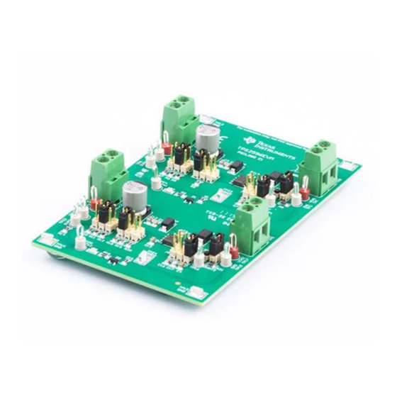
TPS2596EVM: Evaluation Module for TPS2596xx
This user's guide describes the evaluation module (EVM) for the TPS2596xx. The TPS2596xx is an eFuse
with precision current limit, 2.7-V to 19-V supply voltage operation, programmable undervoltage,
overvoltage, overcurrent and inrush current protection features.
...................................................................................................................
1
1.1
1.2
....................................................................................................................
2
...................................................................................................................
3
4
4.1
4.2
4.3
5
5.1
6
1
2
3
4
5
6
7
...................................................................................................................
8
9
1
2
3
4
5
6
7
8
9
10
11
12
SLVUBN7A - April 2019 - Revised August 2019
Submit Documentation Feedback
.......................................................................................................
...................................................................................................
.....................................................................................................
.....................................................................................................
.......................................................................................
.......................................................................................
.....................................................................................................
.....................................................................................................
...................................................................................................
..........................................................................................
........................................................................................
......................................................................................
.......................................................................................................
................................................................................................................
.....................................................................................................
...........................................................................................................
.................................................................................
...........................................................................................
Copyright © 2019, Texas Instruments Incorporated
SLVUBN7A - April 2019 - Revised August 2019
Contents
......................................................................
List of Figures
................................................................
...............................................................
List of Tables
............................................................................
................................................................................
................................................................................
......................................................................
............................................................
......................................................................
............................................................
.................................................................
TPS2596EVM: Evaluation Module for TPS2596xx
User's Guide
2
2
2
3
4
4
4
6
7
14
14
16
4
7
10
11
12
13
14
15
15
3
5
5
6
8
8
8
9
9
11
11
16
1
Advertisement
Table of Contents

Related Manuals for Texas Instruments TPS2596EVM


Summary of Contents for Texas Instruments TPS2596EVM
-
Page 1: Table Of Contents
Power Supply Setting for TPS2596EVM ................Default Jumper Setting for TPS2596EVM ..............TPS2596 DMM Readings at Different Test Points ............TPS2596EVM Oscilloscope Setting for Current Limit Test ..............TPS2596EVM Jumper Settings for Current Limits ............TPS2596EVM Oscilloscope Setting for Overvoltage Test .............. -
Page 2: Introduction
• Push button RESET signal • Onboard 15-V TVS for input transient protection. The TVS needs to be removed if TPS2596EVM is intended to operate at input voltages greater than 15 V. • Schottky diode at output prevents a negative spike when the load is removed EVM Applications •... -
Page 3: Description
Description The TPS2596EVM enables full evaluation of the TPS2596xx devices. The EVM supports two versions (Auto-Retry and Latch-Off) of the devices on two Channels (CH1 and CH2, respectively). Input power is applied at J1 (CH1) and J9 (CH2) while J2 (CH1) and J10 (CH2) provide the output connection to the load. -
Page 4: Schematics
This section describes the physical access, test equipment and set up, and the test setup and procedures for this EVM. Physical Access Table 2 lists the TPS2596EVM input and output connector functionality. TPS2596EVM: Evaluation Module for TPS2596xx SLVUBN7A – April 2019 – Revised August 2019 Submit Documentation Feedback Copyright ©... -
Page 5: Input And Output Connector Functionality
CH2 Output from the EVM TP20 FLTb2 CH2 Fault test point TP9, TP14 TP15, TP10 TP24 SGND1 CH2 Signal GND SLVUBN7A – April 2019 – Revised August 2019 TPS2596EVM: Evaluation Module for TPS2596xx Submit Documentation Feedback Copyright © 2019, Texas Instruments Incorporated... -
Page 6: Test Equipment And Setup
Loads One resistive load or equivalent which can tolerate up to 3-A DC load at 12 V and are capable of the output short. TPS2596EVM: Evaluation Module for TPS2596xx SLVUBN7A – April 2019 – Revised August 2019 Submit Documentation Feedback... -
Page 7: Test Setup And Procedures
General Configurations www.ti.com Test Setup and Procedures Figure 2 shows a typical test setup for the TPS2596EVM. Connect J1/J9 to the power supply and J2/J10 to the load. Oscilloscope Voltmeter Negative Negative Load Power Suppl y Posi tive Posi tive... -
Page 8: Power Supply Setting For Tps2596Evm
TPS2596EVM 12 ± 0.2 V 3 A ± 0.25 A CH2(J9) 3. Turn off the power supply. Hook up CH1 and CH2 of the TPS2596EVM assembly as shown in Figure 4. The default EVM jumper setting is shown in Table Table 6. -
Page 9: Tps2596Evm Oscilloscope Setting For Current Limit Test
1. Verify all three current limits (CH1 and CH2, with only 1 channel powered at a time) and verify the latch and auto-retry feature. Setup the oscilloscope as shown in Table (1) (2) Table 8. TPS2596EVM Oscilloscope Setting for Current Limit Test Oscilloscope Setting CH1 Probe Points CH2 Probe Points... -
Page 10: J4 = 3-4, Current Limit (1.0 A) Test Auto Retry (Ch1)
(based on the respective jumper setting) as shown in Table TPS2596EVM: Evaluation Module for TPS2596xx SLVUBN7A – April 2019 – Revised August 2019 Submit Documentation Feedback Copyright © 2019, Texas Instruments Incorporated... -
Page 11: J11 = 3-4, Current Limit (1.0 A) Test With Latch (Ch2)
50 ms/div 50 ms/div 2. The jumper setting for the different overvoltage limit test is shown in Table Table 11. TPS2596EVM Jumper Settings for Over Load Limits CH1 Output Clamp CH2 Overvoltage Lockout CH1 Jumper Setting, J3 CH2 Jumper Setting, J12... -
Page 12: J3 = 1-2, Overvoltage Test (Ch1)
FLTb2 RED LED (D5) turns ON. Figure 6 shows overvoltage test for jumper setting, J12 = 1-2. TPS2596EVM: Evaluation Module for TPS2596xx SLVUBN7A – April 2019 – Revised August 2019 Submit Documentation Feedback Copyright © 2019, Texas Instruments Incorporated... -
Page 13: J12 = 1-2, Overvoltage Test (Ch2)
General Configurations www.ti.com Figure 6. J12 = 1-2, Overvoltage Test (CH2) SLVUBN7A – April 2019 – Revised August 2019 TPS2596EVM: Evaluation Module for TPS2596xx Submit Documentation Feedback Copyright © 2019, Texas Instruments Incorporated... -
Page 14: Evm Assembly Drawings And Layout Guidelines
Figure 7 through Figure 9 show component placement and layout of the EVM. Figure 7. Top Side Placement TPS2596EVM: Evaluation Module for TPS2596xx SLVUBN7A – April 2019 – Revised August 2019 Submit Documentation Feedback Copyright © 2019, Texas Instruments Incorporated... -
Page 15: Top Layer
EVM Assembly Drawings and Layout Guidelines www.ti.com Figure 8. Top Layer Figure 9. Bottom Layer SLVUBN7A – April 2019 – Revised August 2019 TPS2596EVM: Evaluation Module for TPS2596xx Submit Documentation Feedback Copyright © 2019, Texas Instruments Incorporated... -
Page 16: Bill Of Materials (Bom)
Bill of Materials (BOM) www.ti.com Bill of Materials (BOM) Table 12 lists the BOM for this EVM. Table 12. TPS2596EVM Bill of Materials Package Alternate Part Alternate Designator Quantity Value Description Part Number Manufacturer Reference Number Manufacturer !PCB Printed Circuit Board PSIL085 330 uF CAP, AL, 330 uF, 25 V, +/- 20%, 0.16... - Page 17 Bill of Materials (BOM) www.ti.com Table 12. TPS2596EVM Bill of Materials (continued) Package Alternate Part Alternate Designator Quantity Value Description Part Number Manufacturer Reference Number Manufacturer RES, 402 k, 1%, 0.125 W, AEC-Q200 402 k 0805 ERJ-6ENF4023V Panasonic Grade 0, 0805 R6, R11 RES, 909, 0.1%, 0.125 W, 0805...
- Page 18 Bill of Materials (BOM) www.ti.com Table 12. TPS2596EVM Bill of Materials (continued) Package Alternate Part Alternate Designator Quantity Value Description Part Number Manufacturer Reference Number Manufacturer RES, 100 k, 1%, 0.125 W, AEC-Q200 100 k 0805 CRCW0805100KFKEA Vishay-Dale Grade 0, 0805 TPS2596EVM: Evaluation Module for TPS2596xx SLVUBN7A –...
- Page 19 Updated EVM Setup with Test Equipment Figure 2 .................... • Updated Figure Figure 8 Figure 9 .................... • Updated Bill of Materials (BOM) Table 12 SLVUBN7A – April 2019 – Revised August 2019 Revision History Submit Documentation Feedback Copyright © 2019, Texas Instruments Incorporated...
- Page 20 TI products. TI’s provision of these resources does not expand or otherwise alter TI’s applicable warranties or warranty disclaimers for TI products. Mailing Address: Texas Instruments, Post Office Box 655303, Dallas, Texas 75265 Copyright © 2019, Texas Instruments Incorporated...
Need help?
Do you have a question about the TPS2596EVM and is the answer not in the manual?
Questions and answers