Table of Contents
Advertisement
Quick Links
One Technology Way • P.O. Box 9106 • Norwood, MA 02062-9106, U.S.A. • Tel: 781.329.4700 • Fax: 781.461.3113 • www.analog.com
Evaluation Board for the AD5254 Digital Potentiometer
FEATURES
Full featured evaluation board for the AD5254
Several test circuits
Various ac/dc input signals
PC control via a separately purchased system development
platform (SDP)
PC control software
12 extra bytes in EEMEM for user-defined information
Resistor tolerance error stored in EEMEM
PACKAGE CONTENTS
EVAL-AD5254SDZ evaluation board
CD that includes
Self-installing software that allows users to control the
board and exercise all functions of the device
Electronic version of the AD5254 data sheet
Electronic version of the UG-236 document
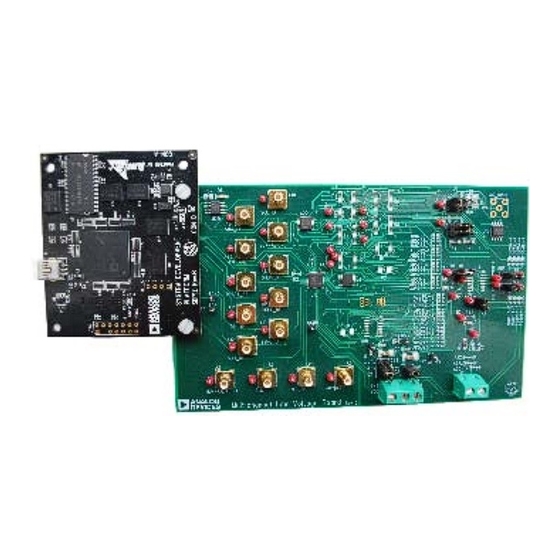
DIGITAL PICTURE OF EVALUATION BOARD WITH SYSTEM DEVELOPMENT PLATFORM
PLEASE SEE THE LAST PAGE FOR AN IMPORTANT
WARNING AND LEGAL TERMS AND CONDITIONS.
SYSTEM DEVELOPMENT
PLATFORM
Rev. 0 | Page 1 of 16
Evaluation Board User Guide
GENERAL DESCRIPTION
This user guide describes the evaluation board for evaluating the
AD5254—a quad-channel, 256-position, nonvolatile memory
digital potentiometer. With versatile programmability, the AD5254
allows multiple modes of operation, including read/write access
in the RDAC and EEMEM registers, increment/decrement of
resistance, resistance changes in ±6 dB scales, wiper setting read-
back, and extra EEMEM for storing user-defined information,
such as memory data for other components or a lookup table.
The AD5254 supports a dual-supply ±2.25 V to ±2.75 V operation
and a single-supply 2.7 V to 5.5 V operation, making the device
suited for battery-powered applications and many other appli-
cations. In addition, the AD5254 uses a versatile I
interface that operates in fast mode, allowing speeds of up to
400 kbps and supporting the selection of up to four different I
addresses.
The EVAL-AD5254SDZ can operate in single-supply and dual-
supply mode and incorporates an internal power supply from
the USB.
Complete specifications for the AD5254 part can be found in
the
AD5254
data sheet, which is available from Analog Devices,
Inc., and should be consulted in conjunction with this user
guide when using the evaluation board.
EVAL-AD5254SDZ
Figure 1.
UG-236
2
C serial
2
C
Advertisement
Table of Contents

Subscribe to Our Youtube Channel
Related Manuals for Analog Devices EVAL-AD5254SDZ


Summary of Contents for Analog Devices EVAL-AD5254SDZ
-
Page 1: Features
Electronic version of the AD5254 data sheet addresses. Electronic version of the UG-236 document The EVAL-AD5254SDZ can operate in single-supply and dual- supply mode and incorporates an internal power supply from the USB. Complete specifications for the AD5254 part can be found in... -
Page 2: Table Of Contents
UG-236 Evaluation Board User Guide TABLE OF CONTENTS Features ....................1 Test Circuits ...................4 Package Contents ................1 Evaluation Board Software ...............6 General Description ................. 1 Installing the Software ..............6 Digital Picture of Evaluation Board with System Development Running the Software ..............6 Platform ..................... -
Page 3: Evaluation Board Hardware
In single-supply mode, the evaluation board can be powered by a PC, via the SDP board, using the EVAL-AD5254SDZ in either from the SDP port or externally by the J1-1, J1-2, and single-supply mode. -
Page 4: Test Circuits
UG-236 Evaluation Board User Guide – V TEST CIRCUITS 1µF AC + DC The EVAL-AD5254SDZ incorporates several test circuits to evaluate the AD5254 performance. AC_INPUT RDAC0 RDAC0 can be operated as a digital-to-analog converter (DAC), W1_BUF as shown in Figure 2. - Page 5 Evaluation Board User Guide UG-236 In addition, R36 can be used to achieve a pseudologarithmic R43 and R42 can be used to set the maximum and minimum attenuation. To do so, adjust the R36 resistor until a desirable gain limits. transfer function is found.
-
Page 6: Evaluation Board Software
After installation is completed, power up the evaluation board as described in the Power Supplies section. Plug the EVAL-AD5254SDZ into the SDP board and the SDP board into the PC using the USB cable included in the box. When the software detects the evaluation board, follow the instructions that appear to finalize the installation. -
Page 7: Software Operation
SOFTWARE OPERATION RDAC register values. This function can be used to verify The main window of the EVAL-AD5254SDZ software is whether the write operation was completed successfully. divided into the following sections: QUICK COMMANDS, The scroll bars are updated upon each write transfer. -
Page 8: Evaluation Board Schematics And Artwork
UG-236 Evaluation Board User Guide EVALUATION BOARD SCHEMATICS AND ARTWORK Figure 12. Schematic of Multiboard Digital Potentiometers Rev. 0 | Page 8 of 16... - Page 9 Evaluation Board User Guide UG-236 U15-C U15-A AC_INPUT AC + DC AD8652AR DAC + FLOATING DAC + BW AD8403-1 W1-1 W1_BUF BUF-W1 AD5204-1 W1-2 AD5233-1 W1-3 U14-A AD8618ARZ AD5162-1 W1-4 AD5232-1 W1-5 ADN2850-1 W1-6 AD5235-1 W1-7 AD5254-1 W1-8 PSEUDOLOG ATTENUATOR AD5252-1 W1-9 AD5172...
- Page 10 UG-236 Evaluation Board User Guide Figure 15. Schematic of AD5254 Power Supplies and Other Channels Rev. 0 | Page 10 of 16...
- Page 11 Evaluation Board User Guide UG-236 Figure 16. Schematic of SDP Connector Rev. 0 | Page 11 of 16...
- Page 12 UG-236 Evaluation Board User Guide Figure 17. Component Side View Figure 18. Component Placement Drawing Figure 19. Layer 2 Side PCB Drawing Rev. 0 | Page 12 of 16...
- Page 13 Evaluation Board User Guide UG-236 Figure 20. Layer 3 Side PCB Drawing Figure 21. Solder Side PCB Drawing Rev. 0 | Page 13 of 16...
-
Page 14: Ordering Information
SHDN_BF, SYNC_BF, MUX-A0|CS, MUX-A1|DACSEL, MUX-A2|U/D, O1, O2, DIN_BF, CLK, B1, B2, B3, B4, V1, V2, VOUT, VOUT2, VOUT3, VOUT4, W1, W1_BUF, W2, W3, W4, WP_BUF AD5243 Analog Devices AD5243 AD5162 Analog Devices AD5162 AD5172 Analog Devices AD5172 AD5233 Analog Devices AD5233... - Page 15 Evaluation Board User Guide UG-236 NOTES Rev. 0 | Page 15 of 16...
- Page 16 By using the evaluation board discussed herein (together with any tools, components documentation or support materials, the “Evaluation Board”), you are agreeing to be bound by the terms and conditions set forth below (“Agreement”) unless you have purchased the Evaluation Board, in which case the Analog Devices Standard Terms and Conditions of Sale shall govern. Do not use the Evaluation Board until you have read and agreed to the Agreement.
Need help?
Do you have a question about the EVAL-AD5254SDZ and is the answer not in the manual?
Questions and answers