Table of Contents
Advertisement
Quick Links
Advertisement
Table of Contents

Related Manuals for Tescom RMP-X1


Summary of Contents for Tescom RMP-X1
- Page 1 UPS REMOTE MONITORING PANEL RMP-X1 INSTALLATION AND USER'S GUIDE...
-
Page 2: Table Of Contents
Thank you for choosing our product. UPS Remote Monitoring panel is developed by expert R&D personnel carefully and became a product. You can find all information on the remote monitoring panel in this document. Remote monitoring panel shall briefly referred as RMP. (Remote Monitoring Panel) Special Situations •... -
Page 3: Presentation
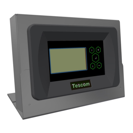
1. PRESENTATION 1.1 Package Opening and Content Control Remote monitoring panel and pedestal 5Vdc 1A Supply adapter RS232 UPS connection cable (CC05) Installation and User's Guide 1.2 View of Remote Monitoring Panel Functions Remote monitoring panel is developed for remotely monitoring UPS stat s information and measured parameters. -
Page 4: Front Panel Functions
1.4 Front panel functions Selection buttons TFT Screen Enter (OK) button TFT Screen : The screen indicating status information received from UPS and values measured. Selection buttons : Used for roaming between menus and setting options. Enter (OK) button : Used for entering the selected menu or confirming the selected option. Technical Features Function Parameter... -
Page 5: Installation
This connection type is used for the max. 25 m short distance. Connection shall be made with CC05 coded cable. See the next topic for pin explanations of CC05 Cable. • RMP-X1 • RS485 connection This connection type is used for distances longer than 25 meters with UPS. As UPS has standard RS232 communication output, RSC24 model RS232-RS485 converter adapter should be used to establish communication with RMP. -
Page 6: Explanations On Cable Pin Between Ups - Remote Monitoring Panel
RMP-X1 Explanations on Cable pin between UPS - Remote monitoring panel • CC05 RS232 communication cable (max. 25m) RMP COM1 communication port or PC (COM PORTS) RMP COM2 • CC11 RS485 communication cable (distances further than 25m) CONNECTOR CONNECTOR MC1.5/5-ST-3.81 MC1.5/5-ST-3.81... -
Page 7: Mechanical Installation
2.3 Mechanical Installation You can either install the remote monitoring panel on the wall or use on the table by placing on the pedestal. There are 2 connection points to install to the wall. Dimension of installation points are given below. 220 mm 2.4 Before Starting Control the communication connection between UPS and more monitoring panel. -
Page 8: Menus And Sub-Parameters (Upper Line)
3.2 Menus and Sub-parameters (Upper Line) View of a 3 phase / 3 phase device in the remote monitoring panel is different than the screen view of 3 phase / 1 phase. LCD screen views automatically vary depending on the device protocol. Screen view and explanations of a remote monitoring panel connected to a 3/3 phase UPS are given in the table below. - Page 9 – !!!!! MEASURES GENERAL !!!!! Indicates the UPS Temperature values. !!!!! Lowest line is the alarm indicator. -------- Alarm Line -------- ALARM LOGS SHOULD BE SEEN OVER THE ALARMS LOGS MENU DEVICE, NOT THROUGH THE REMOTE CONTROL PANEL. ...
-
Page 10: Ups Status Information And Alarm Messages (Lower Line)
SERVICE MENU HOURMETER ENTER<FAULT RESET> ------------------------------------------------------ ------------------------------------------------------ Ones other than total working hour data are ------------------------------------------------------ only used for monitoring. … LOGOUT RELAY CONTACTS ENTER EXIT -------- Alarm Line -------- ADJUST MENU SERV. PASS Made through UPS except USER PASW main panel settings. - Page 11 TH1 heat sensor heat is lower than the adjusted alarm level L03 TH1 LOW HEAT Warning L04 TH2 LOW HEAT Warning TH2 heat sensor heat is lower than the adjusted alarm level FAN maintenance period expired warning L05 FAN MAINTENANCE Warning ACCUMULATOR maintenance period expired warning L06 ACCUMULATOR...
- Page 12 TX300 protocol alarms A1 BYPASS FAILURE Bypass system failure A2 INVERTER FAILURE Inverter starting signals not established A3 3 OVERTEMP Over-heating occurred for 3 times in the device within half an hour. A4 OUT FAILURE UPS output voltage found as out-of-tolerance for 3 times within half an hour A5 BATT AUT END Accumulators emptied as the result of electricity interruption Status normal.
-
Page 13: Special Situations While Remote Monitoring Panel Operates
Status Information RECTIFIER START ! Rectifier started to operate. INVERTER START ! Inverter started to operate. MAINT SWITCH ON ! Maintenance Bypass Switch is on. MANUEL BYPASS ! Load manually transferred to grid. STATUS ALARM ! Alarm status message on the lower line means alarm status situation is temporary STATUS NORMAL ! UPS operates normally. - Page 15 AGKK13150 08/2018...
Need help?
Do you have a question about the RMP-X1 and is the answer not in the manual?
Questions and answers