Table of Contents
Advertisement
Quick Links
Advertisement
Table of Contents

Related Manuals for heat-timer HTC


Summary of Contents for heat-timer HTC
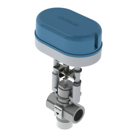
- Page 1 INSTALLATION AND OPERATION MANUAL HTC ACTUATORS 059297-00 REV. H...
- Page 2 WARNING This Heat-Timer Motorized Tempering Valve is strictly an operating valve. It should never be used as a “Fail Safe“ or “Anti-Scald“ valve. A separate Anti-Scald device can be installed in conjunction with this motorized tempering valve. All equipment must have their...
-
Page 3: Table Of Contents
HTC ACTUATOR ONLY FOR REPLACEMENT GENERAL WIRING ETV STAINLESS VALVE AND ACTUATOR KITS 24V FLOATING IP 65 RATED HTC ACTUATOR ETV WIRING ETV VALVE AND HTC ACTUATOR DIMENSIONAL ETV PLUS WIRING SPECIFICATIONS ETV PLATINUM PLUS WIRING MODULATION CURRENT VOLTAGE MODULATION 4–20mA... -
Page 4: Overview
Loss of Power (LOP) Capacitor. The HTC is also available with IP 65 rating that allows outdoor installation of the valve and actuator, but not the Heat Timer controller. The HTC actuator with IP 65 is only available with the LOP Capacitor. -
Page 5: Etv Valve And Htc Actuator Dimensional
OVERVIEW ETV VALVE AND HTC ACTUATOR DIMENSIONAL MAINTAIN 12 INCHES MAINTAIN 12 INCHES MINIMUM FOR MINIMUM FOR SERVICING CLEARANCE SERVICING CLEARANCE 7 ¾” MAINTAIN 18 INCHES MINIMUM FOR SERVICING CLEARANCE DIMENSION ASSEMBLY ½” 3 ¹/ ” 2” 10 ½” 2 ³/ ”... -
Page 6: Installation Guidelines
INSTALLATION GUIDELINES FIGURE 1 ALLOWABLE MOUNTING POSITION FOR THE HTC ACTUATOR STANDARD AND HTC ACTUATOR WITH LOP CAPACITOR NOTE The HTC Actuator with IP 65 Rating can only be mounted in the vertical position to avoid potential penetration of water into the motor circuit. -
Page 7: Manual Override Operation
To return the HTC Actuator back to automatic operation simply return the Manual tab to its upward position. WIRE TERMINAL ACCESS To gain access to the HTC Actuator wire terminals, dip switches and on those actuators with a LOP Capacitor the Capacitor Jumper, the cover must be remove. -
Page 8: Applications
Remove the actuator cover to access the wire terminals by unsnapping the front of the black cover and lifting toward the rear of the actuator. Prior to removing the wires from the terminals, it is a best practice to label the wiring to ensure proper wiring to the HTC Actuator. • Label Terminal G wire as 24V •... - Page 9 For Dip Switch and Capacitor Jumper (if applicable) settings based on valve configuration reference page 20. For installation completion and calibration of the HTC actuator reference page 23. To remove the actuator cover remove the mounting screw (1) using a Phillips screwdriver as shown on page 7.
-
Page 10: Replacement Of The Etv Plus Tr1000 Actuator
Remove the actuator cover to access the wire terminals by removing the (2) mounting screws on the front red cover. Prior to removing the wires from the terminals, it is a best practice to label the wiring to ensure proper wiring to the HTC Actuator. • Label Terminal B wire as 24V. - Page 11 For wiring of the new HTC actuator reference page 16. For Dip Switch and Capacitor Jumper (if applicable) settings based on valve configuration reference page 20. For installation completion and calibration of the HTC actuator reference page 23. MANUAL LEVER...
-
Page 12: Replacement Of An Existing Htc Actuator
APPLICATIONS REPLACEMENT OF AN EXISTING HTC ACTUATOR WARNING ELECTRICAL SHOCK HAZARD! Disconnect electrical power to the device before servicing or making any electrical connections. Failure to do so may result in severe personal injury or death. Follow all local and state electrical codes when installing the unit. All wiring must meet or exceed local, state, federal codes and requirements. - Page 13 For wiring of the new HTC actuator reference page 16. For Dip Switch and Capacitor Jumper (if applicable) settings based on valve configuration reference page 20. For installation completion and calibration of the HTC actuator reference page 23. HTC ACTUATOR...
-
Page 14: Installation On Bronze Valve Body
6. Mount the HTC Actuator onto the valve body making sure the Square Nut is in the U-channel of the actuator. Insert the U-bolt aligning the valve body groove with the actuator. If needed adjust the position of the actuator manually. -
Page 15: Installation On Stainless Steel Valve Body
Ensure the HTC Actuator is at the lowest position by manual positioning it. See page 7. Ensure the valve stem is at its lowest position by pressing down on the stem. Mount the HTC Actuator onto the valve body making sure the U-channel of the actuator aligns with the valve stem groove. -
Page 16: Wiring
Route all wiring through the bottom of the actuator. Use the proper NM connector to secure the wiring and avoid potential damage to the wiring. NOTE: On HTC Actuator with IP 65 rating the actuator is provided with a Liquid Tight Conduit Connector fitting, see figure 8. Liquid Tight conduit is required for any outdoor installations. Check local, state electrical codes for compliance. -
Page 17: 24V Floating
NOTE On existing wiring with a M800 actuator an external 24V transformer provided power to the actuator. This transformer can be eliminated with the HTC actuator and 24V power can be supplied through the ETV panel. 059297-00 REV. H HEAT-TIMER CORP. -
Page 18: Etv Plus Wiring
WIRING ETV PLUS 24 VAC 120 VAC ACTUATOR POWER 0–10 VOLTAGE MODULATING SIGNAL EARTH GROUND 120 VAC ETV PLATINUM PLUS 24 VAC 120 VAC ACTUATOR POWER 0–10 VOLTAGE MODULATING SIGNAL EARTH GROUND 120 VAC HEAT-TIMER CORP. 059297-00 REV. H... -
Page 19: Modulation Current Voltage
WIRING MODULATION CURRENT VOLTAGE HTC ACTUATOR VALVE CONTROLLER REFERENCE MODULATION CURRENT 120V VOLTAGE DIP SWITCH SETTINGS, POWER SUPPLY FIGURE 14–16, PAGE 22 TRANSFORMER MODULATION 4–20mA HTC ACTUATOR VALVE CONTROLLER 120V REFERENCE MODULATION 4–20MA DIP POWER SWITCH SETTING, ON FIGURE 13, PAGE 22... -
Page 20: Configuration And Settings
Dip Switch 1 must be in the ON position as shown. The Capacitor Jumper (if applicable) must remain as installed by the factory. On loss of power the actuator will push the valve stem downward to the full COLD position. HEAT-TIMER CORP. 059297-00 REV. H... -
Page 21: Valve Installation-Alternate Configuration
1 2 3 4 5 6 7 COLD PORT FIGURE 11 HTC ACTUATOR—IP 65 VERSION WITH LIQUID TIGHT FITTING When the ETV valve is installed as shown in the Alternate Configuration, the following applies: Dip Switch 1 must be in the OFF position as shown. - Page 22 Reference Modulation Current Voltage wiring diagram on page 19. FIGURE 16 DIP SWITCH SETTING FOR A 2–10V PROPORTIONAL SIGNAL INPUT 1 2 3 4 5 6 7 Reference Modulation Current Voltage wiring diagram on page 19. HEAT-TIMER CORP. 059297-00 REV. H...
-
Page 23: Led Status
CALIBRATION NOTICE Each time the HTC Actuator is mounted onto the valve, the steps outline in HTC Actuator Calibration must be performed to ensure proper operation and to determine optimum stroke of the actuator. Ensure the HOT supply to the valve is isolated by closing the isolation valve on the HOT supply piping. -
Page 24: Startup
IP 65 INSULATION KIT To provide additional protection to the HTC Actuator IP 65, an optional insulation boot (P/N 905045-00) is available. The insulation kit consist of a 2 part shell that will Velcro together. The insulation kit only covers the actuator, not the valve body. -
Page 25: Notes
NOTES 059297-00 REV. H HEAT-TIMER CORP. - Page 26 NOTES HEAT-TIMER CORP. 059297-00 REV. H...
- Page 27 WARRANTIES AND LIMITATIONS OF LIABILITY AND DAMAGE: Heat-Timer Corporation warrants that it will replace, or at its option, repair any Heat-Timer Corporation manufactured product or part thereof which is found to be defective in material workmanship within one year from the date of installation only if the warranty registration has been completed online within 30 days of the date of installation.
- Page 28 20 NEW DUTCH LANE, FAIRFIELD, NJ 07004 PHONE: 973-575-4004 FAX: 973-575-4052 HEAT-TIMER.COM...
Need help?
Do you have a question about the HTC and is the answer not in the manual?
Questions and answers