Table of Contents
Advertisement
Quick Links
Limit Controller
User Guide
/
DIN
1
32
Available Soon
PM3
For Configurations:
PM(3,6)(L,M)_ _ _-_A_ _G_ _
1241 Bundy Boulevard., Winona, Minnesota USA 55987
Phone: +1 (507) 454-5300, Fax: +1 (507) 452-4507
http://www.watlow.com
10-42072 Rev. -, July 2020, Made in the U.S.A.
PM6
TOTAL
CU
CUS S T T O O M M ER
ER
S S A A TIS
TISF F A A CT
CTI I O O N N
3 Y ear Warranty
ISO 9001
ISO 9001
Registered Company
Winona, Minnesota USA
Advertisement
Table of Contents

Related Manuals for Watlow PM LEGACY PM3


Summary of Contents for Watlow PM LEGACY PM3
- Page 1 CTI I O O N N 3 Y ear Warranty ISO 9001 ISO 9001 Registered Company Winona, Minnesota USA 1241 Bundy Boulevard., Winona, Minnesota USA 55987 Phone: +1 (507) 454-5300, Fax: +1 (507) 452-4507 http://www.watlow.com 10-42072 Rev. -, July 2020, Made in the U.S.A.
- Page 2 7. Watlow reserves the right to charge for no trouble found (NTF) returns. Copyrights - Patents Pending This PM LEGACY™ Limit User’s Guide is copyrighted by Watlow Electric, Inc., © July 2020 with all rights reserved.
-
Page 3: Table Of Contents
Table of Contents Table of Contents ..........3 Chapter 1: Overview . - Page 4 Table of Contents (cont.) Chapter 7: Factory Page ........74 Custom .
- Page 5 Safety Information We use note, caution and warning symbols throughout this book to draw your attention to important operational and safety information. A “NOTE” marks a short message to alert you to an important detail. A “CAUTION” safety alert appears with information that is important for protecting your equipment and performance.
-
Page 6: Chapter 1: Overview
Chapter 1: Overview Introduction The Watlow® LEGACY™ SERIES panel mount controller is an industry leading PID controller that al- lows optimal performance utilizing simple control and menu functionality without complex features. It is ideally suited for basic applications and usage levels. -
Page 7: A Conceptual View Of The Pm
Overview A Conceptual View of the PM The flexibility of the PM software and hardware allows for a large range of configurations. Ac- quiring a better understanding of the controller’s overall functionality and capabilities while at the same time planning out how the controller can be used will deliver maximum effectiveness in your application. -
Page 8: Internal Functions
Overview Continued) Outputs The Output Wire Terminals are located on the Internal Functions back side of the controller. See Figure 3. The The controller will use input signals to calculate Outputs properly wired and configured can a value and then perform an operation. A sample perform various functions or actions in response of some functions may be as simple as: to information provided by a function such as,... - Page 9 • Increases user and equipment safety for over • Speeds up user’s system documentation and under-temperature conditions. Three-Year Warranty Function Key • Demonstrates Watlow’s reliability and product support • Enables simple, one-touch operation of us- er-defined, repetitive activities High-Amperage Power Control Output (1/16...
-
Page 10: Input Events And Output Events
Input Events and Output Events Input events are internal state input event 2. The setting of Digital Input Function (Setup Page, Digital Input/Out- put Menu) does not change the relationship between the input and the event. An input will still control the input event state, even if Digital Input Function is set to None. - Page 11 PM LEGACY™ Limit PM Models - Input/Output (no communications options 2, 3, 5 or 6) Universal Sensor Input, Configuration Communications, EZ-ZONE™ PM Enhanced Limit Controller Red/Green 7-Segment Display Output Input Functions Functions Output 1 Off, Limit, None, Switched dc/open collector, Limit Analog Input 1 Alarm...
- Page 12 PM LEGACY™ Limit All Models System Diagram (No communications options 2, 3, 5 or 6) Universal Sensor Input, Configuration Communications, EZ-ZONE™ PM Limit Controller Red/Green 7-Segment Display Output Input Functions Functions Output 1 Off, Limit, None, Switched dc/open collector, Limit Alarm Analog Input 1 Form C mechanical (5 A) relay...
-
Page 13: Chapter 2: Install & Wiring
Chapter 2: Install & Wiring INSTALLTION 1. For a PM3 Controller, make the panel cutout using the measurements shown on page 6. 2. For a PM6 Controller, make the panel cutout using the measurements shown on page 7. 3. Remove the green terminal connectors and the mounting collar assembly. -
Page 14: Dimensions
Dimensions 1/32 DIN (PM3) 2.10in 0.40in 53.3mm 10.2mm 1.22in 30.9mm 1.38in 35.2mm Mounting Panel 4.22in 107.2mm 1/32 DIN (PM3) Recommended Panel Spacing 44.96 to 45.47 mm (1.77 to 1.79 inches) Recommended panel spacing 22.2 to 22.5 mm (0.87 to0.89 inches) 21.6 mm panel thickness 1.53 to 9.52 mm (0.85 in) -
Page 15: 1/16 Din (Pm6)
1/16 DIN (PM6) 2.10 0.40 53.34 10.16 2.10 53.34 1.38 35.16 4.22 Mounting Panel 107.18 1/16 DIN (PM6) Recommended Panel Spacing 44.96 to 45.47 mm (1.77 to 1.79 inches) Recommended panel spacing 44.96 to 45.47 mm (1.77 to 1.79 inches) 21.6 mm panel thickness 1.53 to 9.52 mm (0.85 in) -
Page 16: Wiring
Wiring Slot A Slot B Terminal Function Configuration Inputs Universal, RTD and Thermistor Inputs S2 (RTD) or current + Universal Sensor S3 (RTD), thermocouple -, current -, volts - Input 1: all configurations or potentiometer wiper, thermistor S1 (RTD), thermocouple + or volts +, thermistor, potentiometer Outputs Switched dc/open collector... - Page 17 Wiring (cont.) DeviceNet™ power DeviceNet™ Communications Positive side of DeviceNet™ bus Slot B: Shield interconnect PM6[L,M] _ _ J-[H,5] AAAG_ _ Negative side of DeviceNet™ bus DeviceNet™ power return Slot A Slot B Terminal Function Configuration EtherNet/IP™ and Modbus ® TCP Communications (cont.) EtherNet/IP™...
- Page 18 Slot Orientation - Back View 1/32 DIN Horizontal PM3 1/16 DIN Vertical PM6 Power Dig I/O 5 & 6 485 Comms Output 1 Output 2 Input 1 Note: Slot B above can also be configured with a communications card. PM Isolation Block Digital Inputs &...
- Page 19 Low Power PM6[L,M] [3,4} _ J-_ A_ _G_ _ ç Warning: Use National Electric (NEC) or • Minimum/Maximum Ratings Slot C other country-specific standard power • 12 to 40V (dc) wiring and safety practices when fuse power wiring and connecting this con- •...
- Page 20 ç Warning: Input 1 Thermocouple PM6[L] _ _ J-_ _ _ _G_ _ Use National Electric (NEC) or • 2kΩ maximum source resistance other country-specific standard Slot A wiring and safety practices when • >20MΩ input impedance wiring and connecting this con- •...
- Page 21 Input 1 Potentiometer PM6[L] _ _ J-_ _ _ _G_ ç Warning: Use National Electric (NEC) • Use a 1kΩ potentiometer. Slot A or other country-specific standard wiring and safety practices when wiring and connecting this controller to a power source and to elec- trical sensors or peripheral devices.
- Page 22 Output 1, 3 Mechanical Relay, Form C ç Warning: Use National Electric (NEC) • 5A at 240V (ac) or 30V or other country-specific Slot A, B (dc) maximum resistive normally open standard wiring and safety practices when wiring and common load connecting this controller to normally closed...
- Page 23 Output 2, 4 Mechanical Relay, Form A ç Warning: Use National Electric (NEC) • 5A at 240VÅ (ac) or 30VÎ Slot B or other country-specific (dc) maximum resistive standard wiring and safety practices when wiring and load connecting this controller to •...
- Page 24 Output 3 Universal Process ç Warning: Use National Electric (NEC) • 0 to 20mA into 800 Ω Slot B or other country-specific volts or current - maximum load negative standard wiring and safety volts + • 0 to 10V (dc) into 1 practices when wiring and 0 to 10 V current +...
- Page 25 Output 4 Switched DC ç Warning: • Maximum open circuit Use National Electric (NEC) Slot B or other country-specific common voltage is 22 to 25V standard wiring and safety (dc) dc - practices when wiring and • 30mA max. per single connecting this controller to dc + a power source and to elec-...
- Page 26 Output 1, 3 Switched DC/Open Collector ç Warning: Use National Electric (NEC) Switched DC Switched DC Slot A, B common or other country-specific • Maximum open circuit dc - (open collector) standard wiring and safety common dc + voltage is 22 to 25V (dc) practices when wiring and connecting this controller to...
- Page 27 Quencharc Wiring Example n this example the Quencharc circuit (Watlow part# User Load 0804-0147-0000) is used to protect PM internal circuitry from the counter electromagnetic force from the induc- Quencharc tive user load when de-energized. It is recommended that this or an equivalent Quencharc be used when con- necting inductive loads to PM outputs.
- Page 28 • Maximum EIA-485 network length: 1,200 meters (4,000 feet) • 1/8th unit load on EIA-485 bus. • Communications instance 2 Slot B PM6[L,M] _ _J - [F,2] _ _ _ G_ _ Modbus-IDA EIA/TIA-485 Watlow Termi- Function Terminal Name nal Label CA or CD T-/R-...
- Page 29 Slot B, E RJ-45 T568B wire col- Slot B, Signal unused unused brown unused receive - brown & white unused unused green receive - unused white & blue unused receive + blue unused transmit - white & green receive + transmit + orange transmit -...
- Page 30 Network Status Indicator State Summary Requirement Not powered, If the device does not have an IP address (or is powered off), Steady Off no IP address the network status indicator shall be steady off. If the device has no established connections, but has ob- No connec- Flashing Green tained an IP address, the network status indicator shall be...
- Page 31 Link Status Indicator Summary Requirement State Not powered, If the device cannot determine link speed or power is off, the Steady Off unknown link network status indicator shall be steady off. speed If cable is wired and connected correctly, the LED will be Green - - - - Green.
- Page 32 485 T+/R+ network. 485 T-/R- • If using a 150 Ω cable Watlow provides internal termination. Place a Termination resistor A jumper across pins trB and B and trA and A. • If external termination is to be used with a 150 Ω cable place a 390 Ω re- sistor across pins VP and B, a 220 Ω...
- Page 33 Connecting a Computer to PM Controls Using B&B 485 to USB Converter Address 2 Address 1 Port Data Format 38,400 baud 8 data bits PC Software Protocol - Standard Bus no parity EZ-ZONE Con gurator software 1 start bit 1 stop bit Use twisted pair wires such as Cat 5 cabling.
-
Page 34: Chapter 3: Keys And Displays
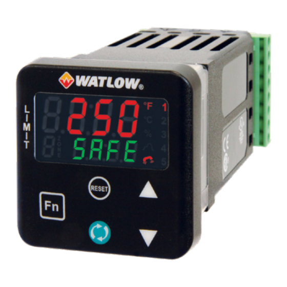
Chapter 3: Keys & Displays Keys & Displays 16 DIN LIMIT Controller Upper Display: Temperature Units Zone Display: On power up, displays Indicator Lights: When [2onE] (found in the the process value, otherwise Indicates whether the Factory Page) is set to on, indi- displays the value of the temperature is displayed in cates the controller zone. -
Page 35: Responding To A Displayed Message
Responding to a Displayed Message An active message will cause the display to toggle between the normal settings and the active message in the upper display and in the green display. attn Your response will depend on the message and the controller settings. Some messages, such as Ramping and Tuning, indicate that a process is underway. -
Page 36: Chapter 4: Home Page
Chapter 4: Home Page Default Home Page Parameters Watlow's patented user-defined menu system improves operational efficiency. The user-defined Home Page provides you with a shortcut to monitor or change the parameter values that you use most often. The default Home Page is shown on the following page. When a parameter normally lo- cated in the Setup Page or Operations Page is placed in the Home Page, it is accessible through both. - Page 37 Models Navigating the PM LEGACY™ Limit Controller PM6 Shown, Applies to All ° ° ° ° Reset Reset Home Page from anywhere: Press the Reset key for two seconds to return to the Home Page. Reset ° ° ° ° Reset Reset Operations Page from Home Page: Press both the Up and Down key...
-
Page 38: Changing The Set Point
Changing the Set Point From the default Home Page the Limit Set Points, high and low, can be changed. If high and low lim- its have been configured push the Advance key one time and the Low Limit Set Point prompt LL. - Page 39 Modifying the Display Pairs The Home Page, being a customized list of as many as 20 parameters, can be configured in pairs of up to 10 via the Display Pairs prompt found in the Global Menu (Setup Page). The listing gLbL d.
-
Page 40: Conventions Used In The Menu Pages
The display can be configured to scroll through the Display Pairs by going to the Setup Page under the Global Menu and changing the Display Time prompt to something greater than 0. If set to 2, the d. t i display will scroll through the pairs every 2 seconds starting with Custom Menu Pair 1 and 2, 3 and 4, etc.. -
Page 41: Communication Protocols
(low order bytes) and (high order bytes). The Modbus specification does not dictate which register should be high or low order therefore, Watlow provides the user the ability to swap this order (Setup Page, Menu) from the default CoЛЏ... -
Page 42: Profibus Dp
PM _ _ _ _ _ - [1] A _ _ _ _ _ Instance 2: PM _ _ _ _ _ - [2] A _ _ _ _ _ To learn more about the Modbus protocol point your browser to http://www.modbus.org. Common Industrial Protocol (CIP) Introduction to CIP Both DeviceNet and EtherNet/IP use open object based programming tools and use the same ad- dressing scheme. -
Page 43: Chapter 5: Operations Page
Chapter 5: Operations PM Operation Page Parameters To navigate to the Operations Page, follow the steps below: 1. From the Home Page, press both the Up and Down keys for three seconds. will appear in the red display and will appear in the green display. oPEr 2. -
Page 44: Analog Input Menu
Operations Page Data Pro- Type Modbus Class fib- Display Parameter Name ram- Range Default Relative Instance Description eter Address Attribute cess hex (dec) opEr Analog Input Menu Analog Input -1,999.000 to - - - - Instance 1 0x68 (104) 4001 float Analog Input Value 9,999.000°F or... -
Page 45: Digital Input/Output Menu
Operations Page Data Pro- Type Modbus Class fib- Display Parameter Name ram- Range Default Relative Instance Description eter Address Attribute cess hex (dec) opEr Digital Input/Output Menu Digital Output (5 to 6) - - - - Instance 5 0x6A (106) 6007 uint Off (62) -
Page 46: Alarm Menu
Operations Page Data Pro- Type Modbus Class fib- Display Parameter Name ram- Range Default Relative Instance Description eter Address Attribute cess hex (dec) Limit (1) Clear (0) - - - - Instance 1 0x70 (112) - - - - 12014 uint Clear Limit No Change (255) - Page 47 Operations Page Data Pro- Type Modbus Class fib- Display Parameter Name ram- Range Default Relative Instance Description eter Address Attribute cess hex (dec) Alarm (1 to 4) - - - - Instance 1 0x6D - - - - 9026 uint Clear (1003) A.
- Page 48 Operations Page Data Pro- Type Modbus Class fib- Display Parameter Name ram- Range Default Relative Instance Description eter Address Attribute cess hex (dec) No Dis- Alarm (1 to 4) No (59) - - - - Instance 1 0x6D 9010 uint - - - - play Alarm Latched...
-
Page 49: Chapter 6: Setup Page
Chapter 6: Setup Page Navigating the Setup Page To navigate to the Setup Page follow the steps below: 1. From the Home Page, press and hold both the Up or Down keys for six seconds. will appear in the red display and will appear in the green display. - Page 50 otpt aLЛЏ Digital Input/Output Menu Output Menu Alarm Menu Output (1 to 4) Digital Input/Output (5 to 6) otpt Alarm (1 to 4) aLЛЏ Function Direction Type a. t y Output Function Instance Function Alarm Source sr. a Output Function Instance Output Process 3 otpt Alarm...
-
Page 51: Analog Input Menu
Setup Page CIP - Class Data Type Modbus Pro- Display Parameter Name stance rame- Range Default Relative fibus Description Attri- Address Index bute cess (dec) Analog Input Menu Analog Input Thermo- Instance 1 0x68 4005 uint Off (62) Sensor Type couple or Map 1 Map 2 (104) - Page 52 Setup Page CIP - Class Data Type Modbus Pro- Display Parameter Name stance rame- Range Default Relative fibus Description Attri- Address Index bute cess (dec) Analog Input -100.00 to Instance 1 0x68 4015 float s. L o Scale Low 100.00 Map 1 Map 2 (104) RWES...
- Page 53 Setup Page CIP - Class Data Type Modbus Pro- Display Parameter Name stance rame- Range Default Relative fibus Description Attri- Address Index bute cess (dec) Analog Input Curve A Instance 1 0x68 - - - - 4038 uint Curve A (1451) t.
-
Page 54: Digital Input/Output Menu
Setup Page CIP - Class Data Type Modbus Pro- Display Parameter Name stance rame- Range Default Relative fibus Description Attri- Address Index bute cess (dec) Analog Input -1,999.000 to - - - - Instance 1 0x68 4001 float Analog Input Value 9,999.000°F or Map 1 Map 2 (104) - Page 55 Setup Page CIP - Class Data Type Modbus Pro- Display Parameter Name stance rame- Range Default Relative fibus Description Attri- Address Index bute cess (dec) Digital Output (5 to 6) Instance 5 0x 6A 6005 uint Off (62) Function Map 1 Map 2 (106) RWES Alarm (6)
-
Page 56: Limit Menu
Setup Page CIP - Class Data Type Modbus Pro- Display Parameter Name stance rame- Range Default Relative fibus Description Attri- Address Index bute cess (dec) Digital Input (5 to 6) 0 to 40 Instance 5 0x6E 10004 uint Function Instance Map 1 Map 2 (110) RWES... - Page 57 Setup Page CIP - Class Data Type Modbus Pro- Display Parameter Name stance rame- Range Default Relative fibus Description Attri- Address Index bute cess (dec) Limit -1,999.000 to 0.0°F or Instance 1 0x70 12003 float LL. s Low Limit Set Point 9,999.000°F or units Map 1 Map 2...
- Page 58 Setup Page CIP - Class Data Type Modbus Pro- Display Parameter Name stance rame- Range Default Relative fibus Description Attri- Address Index bute cess (dec) otpt Output Menu Output Digital (1 to 4) Output 1 Instance 1 0x6A 6005 uint Off (62) Function - Alarm...
- Page 59 Setup Page CIP - Class Data Type Modbus Pro- Display Parameter Name stance rame- Range Default Relative fibus Description Attri- Address Index bute cess (dec) Output Process (3) 1 to 4 Instance 3 0x76 18004 uint Function Instance Map 1Map 2 (118) RWES Set the instance of...
-
Page 60: Output Menu
Setup Page CIP - Class Data Type Modbus Pro- Display Parameter Name stance rame- Range Default Relative fibus Description Attri- Address Index bute cess (dec) Output Process (3) -1,999.000 to 100.0°F Instance 3 0x76 18012 float r. h i Range High 9,999.000°F or or units Map 1Map 2... - Page 61 Setup Page CIP - Class Data Type Modbus Pro- Display Parameter Name stance rame- Range Default Relative fibus Description Attri- Address Index bute cess (dec) Alarm (1 to 4) 0.001 to 1.0°F or Instance 1 0x6D 9003 float A. h y Hysteresis 9,999.000°F or units...
- Page 62 Setup Page CIP - Class Data Type Modbus Pro- Display Parameter Name stance rame- Range Default Relative fibus Description Attri- Address Index bute cess (dec) Alarm (1 to 4) Non- Instance 1 0x6D 9007 uint Non-Latch- A. L A nLAt Latching Latch- Map 1Map 2...
- Page 63 Setup Page CIP - Class Data Type Modbus Pro- Display Parameter Name stance rame- Range Default Relative fibus Description Attri- Address Index bute cess (dec) Alarm (1 to 4) 0 to 9,999 sec- Instance 1 0x6D 9021 uint A. d L Delay Time onds Map 1Map 2...
- Page 64 Setup Page CIP - Class Data Type Modbus Pro- Display Parameter Name stance rame- Range Default Relative fibus Description Attri- Address Index bute cess (dec) Function Key Function Key High Instance 3 0x6E 10001 uint High (37) high Active Level Map 1Map 2 (110) RWES...
- Page 65 Setup Page CIP - Class Data Type Modbus Pro- Display Parameter Name stance rame- Range Default Relative fibus Description Attri- Address Index bute cess (dec) gLbL Global Menu 3005 uint Global °F Instance 1 0x67 °F (30) RWES Display Units Map 1Map 2 (103) °C (15)
- Page 66 Setup Page CIP - Class Data Type Modbus Pro- Display Parameter Name stance rame- Range Default Relative fibus Description Attri- Address Index bute cess (dec) Global None Instance 1 0x(101) 1014 uint User Set 1 USr. S SEt1 Save Settings As Map 1Map 2 USr.S (101)
- Page 67 Setup Page CIP - Class Data Type Modbus Pro- Display Parameter Name stance rame- Range Default Relative fibus Description Attri- Address Index bute cess (dec) Communications (1 9,600 Instance 1 0x96 - - - - 17002 uint 9,600 (188) bAUd 9600 or 2) Map 1Map 2...
- Page 68 Setup Page CIP - Class Data Type Modbus Pro- Display Parameter Name stance rame- Range Default Relative fibus Description Attri- Address Index bute cess (dec) Communications (1 Instance 1 0x96 17051 uint Yes (106) nU. S or 2) Map 1Map 2 (150) nV.S No (59)
- Page 69 Setup Page CIP - Class Data Type Modbus Pro- Display Parameter Name stance rame- Range Default Relative fibus Description Attri- Address Index bute cess (dec) Communications (2) °F Instance 2 0x96 17050 uint °F (30) Display Units Map 1Map 2 (150) °C (15) Select which scale to...
- Page 70 Setup Page CIP - Class Data Type Modbus Pro- Display Parameter Name stance rame- Range Default Relative fibus Description Attri- Address Index bute cess (dec) Communications (2) Instance 2 96 (150) 17051 uint Yes (106) nU. S Non-volatile Save Map 1Map 2 nU.S No (59) If set to Yes all values...
- Page 71 Setup Page CIP - Class Data Type Modbus Pro- Display Parameter Name stance rame- Range Default Relative fibus Description Attri- Address Index bute cess (dec) Communications (2) 0 to 255 - - - - - - - - - - - - 17016 - - - - iP.
- Page 72 Setup Page CIP - Class Data Type Modbus Pro- Display Parameter Name stance rame- Range Default Relative fibus Description Attri- Address Index bute cess (dec) Communications (2) 0 to 255 - - - - - - - - - - - - 17026 - - - - iP.
- Page 73 Setup Page CIP - Class Data Type Modbus Pro- Display Parameter Name stance rame- Range Default Relative fibus Description Attri- Address Index bute cess (dec) Communications (2) 1 to 40 - - - - - - - - - - - - 24010 - - - - ai.
- Page 74 Chapter 7: Factory Page Navigating the Factory Page To navigate to the Factory Page follow the steps below: 1. From the Home Page, press and hold both the Advance and Reset keys for six seconds. 2. Press the Up or Down key to view available menus.
-
Page 75: Custom
Factory Page Class Pro- Data Modbus Param- Parameter Name stance fibus Type Display Range Default Relative Ad- eter Description Attri- and Ac- dress bute cess ** (dec) Cust fcty Custom Custom See: - - - - - - - - 14005 uint None nonE... -
Page 76: Lock Menu
Factory Page Class Pro- Data Modbus Param- Parameter Name stance fibus Type Display Range Default Relative Ad- eter Description Attri- and Ac- dress bute cess ** (dec) Custom (1 to 20) 1 to 4 - - - - - - - - 14003 uint Instance ID RWES... - Page 77 Factory Page Class Pro- Data Modbus Param- Parameter Name stance fibus Type Display Range Default Relative Ad- eter Description Attri- and Ac- dress bute cess ** (dec) Security Setting 0 to 5 Instance 1 0x67 3011 uint SLoC Write Security Map 1 Map 2 (103) SLoC...
-
Page 78: Chapter 7: Factory Page
Factory Page Class Pro- Data Modbus Param- Parameter Name stance fibus Type Display Range Default Relative Ad- eter Description Attri- and Ac- dress bute cess ** (dec) Security Setting 10 to 999 - - - - - - - - 3018 uint pas. -
Page 79: Diagnostics Menu
Factory Page Class Pro- Data Modbus Param- Parameter Name stance fibus Type Display Range Default Relative Ad- eter Description Attri- and Ac- dress bute cess ** (dec) diag FCty Diagnostics Menu Diagnostics 15 characters - - - - - - - - 0x65 115 1009 string... - Page 80 Factory Page Class Pro- Data Modbus Param- Parameter Name stance fibus Type Display Range Default Relative Ad- eter Description Attri- and Ac- dress bute cess ** (dec) Diagnostics 0 to 255 - - - - - - - - - - - - 17014 R iP.
-
Page 81: Calibration Menu
Factory Page Class Pro- Data Modbus Param- Parameter Name stance fibus Type Display Range Default Relative Ad- eter Description Attri- and Ac- dress bute cess ** (dec) Diagnostics 0 to 255 - - - - - - - - - - - - 17017 R iP. - Page 82 Factory Page Class Pro- Data Modbus Param- Parameter Name stance fibus Type Display Range Default Relative Ad- eter Description Attri- and Ac- dress bute cess ** (dec) Calibration (3) -1,999.000 to Instance 3 0x76 18005 float ELo. o Electrical Output 9,999.000 Map 1Map 2 (118)
-
Page 83: Chapter 8: Features
DeviceNet™ (Not available on PM3 or Express version) PROFIBUS DP (Not available on PM3 or Express version) Note: Bluetooth® not available in all countries, contact factory. Watlow® and EZ-ZONE® are registered trademarks of Watlow Electric Manufacturing Company. SMOOTH-TOUCH™ and EZ-LINK™ are trademarks of Watlow Electric Manufacturing Company. - Page 84 Click on the link that follows to acquire the latest version of the PM LEGACY™ Limit User’s Guide. http://www.watlow.com/en/Resources-And-Support/Technical-Library/User-Manuals Once there, simply enter express in the “Keyword” field to find the appropriate document. How to Restore Original PM Factory Settings and Model Number .
-
Page 85: Saving And Restoring Settings
Programming the Home Page Watlow’s patented user-defined menu system improves operational efficiency. The user-defined Home Page provides you with a shortcut to monitor or change the parameter values that you use most of- ten. -
Page 86: Calibration
Calibration Before performing any calibration procedure, verify that the displayed readings are not within pub- lished specifications by inputting a known value from a precision source to the analog input. Next, subtract the displayed value with the known value and compare this difference to the published accura- Negative Calibration Offset will cy range specification for that type... - Page 87 Note: The user may only calibrate one sensor type. If the calibrator interferes with open thermo- couple detection, set Sensor Type in Setup Page sEt, Analog Input Menu to millivolt ЛЏ u instead of Thermocouple to avoid interference between the calibrator and open thermocouple detect circuit for the duration of the calibration process.
-
Page 88: Filter Time Constant
Filter Time Constant Filtering smooths an input signal by applying a first-order filter time constant to the signal. Filtering the displayed value makes it easier to monitor. Filtering the signal may improve the performance of PID control in a noisy or very dynamic system. Unfiltered Input Signal Filtered Input Signal Time... -
Page 89: Range High And Range Low
Range High and Range Low With a process input, you must choose a value to represent the low and high ends of the current or voltage range. Choosing these values allows the controller’s display to be scaled into the actual working units of measurement. -
Page 90: Alarms
To check the firmware revision of your control do one of the following: 1. Cycle power to the control while observing the number in the top display (this momentary numeri- cal display reflects the current installed firmware version). 2. Navigate to the Factory Page by simultaneously pushing and holding the Advance Key and the Re- set Key for approximately 8 seconds and then use the up or down arrow key to navigate to the Di- agnostic Menu. -
Page 91: Latching
Latching A latched alarm will remain active after the alarm condition has passed. It can only be deactivated by the user. An active message, such as an alarm message, will cause the display to toggle between the normal settings and the active message in the up- The alarm state begins when the temperature reaches the Alarm High Set Point per display and... - Page 92 Using Lockout Method 1 (Read and Set Lock) All Pages have security levels assigned where two of those cannot be changed (Home and Setup). Defaults (factory settings) for each are shown below: - Home Page = 1 - Operations Page = 2 (changeable to 1, 2 or 3) - Setup Page = 4 - Profiling Page = 3 (changeable to 1, 2 or 3) - Factory Page = 5*...
-
Page 93: Using Lockout Method 2 (Password Enable)
Another example of Method 1 lockout usage could be that an operator wants read access to all pages while allowing read/write access to the Home Page and the Lockout Menu only. To setup this nar- io follow the steps below: 1. - Page 94 How to Enable Password Security Follow the steps below: 1. From the Home Page, press and hold the Reset Key and the Advance Key for approximately six sec- onds. will appear in the upper display and will appear in the lower display. CUst fCty 2.
-
Page 95: Modbus - Using Programmable Memory Blocks
Formulas used by the User and the Administrator to calculate the Password follows: Passwords equal: 7. User a. If Rolling Password is Off, Password equals User Password roLL p ass pas. u b. If Rolling Password is On, Password equals: (p as . -
Page 96: Cip - Communications Capabilities
CIP. There you will find the Class, Instance and Attribute in hexadecimal, (decimal in parenthesis) which makes up the addressing for both proto- cols. The Watlow implementation of CIP does not support connected explicit messages but fully sup- ports unconnected explicit messaging. -
Page 97: Cip Implicit Assemblies
I/O assembly that would be read or written to. The default assemblies and the assembly size is embedded into the firmware of the PM control. Watlow refers to these as- semblies as the T to O (Target to Originator) and the O to T (Originator to Target) assemblies where the Target is always the PM LEGACY™... -
Page 98: Software Configuration
If you have not yet obtained a copy of this software and have a connection to the Internet, simply click on the link below and download the software from the Watlow web site free of charge. - Page 99 software provides the user with the option of downloading a previously saved configuration as well as the ability to create a configuration off-line to download later. The screen shots that follow will take the user on-line. After clicking the next button above it is necessary to define the communications port that will be used on the PC as shown to the right.
- Page 100 Any Watlow device on the network will appear in this window and would be available for the purpose of configuration or monitoring; simply click on the control of choice. After doing so, the screen below will appear. In the screen shot below notice that the device part number is clearly displayed at the top of the page (yellow highlight added for emphasis).
- Page 101 (saved in) and enter the file name (File name) as well. The default path for saved files follows: Users\”Username”\My Documents\ Watlow\LEGACY™ Configurator\Saved Config- urations The user can save the file to any folder of choice.
-
Page 102: Chapter 9: Appendix
Chapter 9: Appendix Troubleshooting Alarms, Errors and Control Issues Indication Description Possible Cause(s) Corrective Action Alarm won’t Alarm will not clear or • Latching is active • Reset alarm when process clear or reset reset with keypad or is within range or disable digital input latching •... - Page 103 Indication Description Possible Cause(s) Corrective Action Alarm High Sensor input above • Temperature is greater • Check cause of over tem- high alarm set point than alarm set point perature AL. h 1 • Alarm is set to latching and •...
- Page 104 Indication Description Possible Cause(s) Corrective Action No Display No display indication • Power to controller is off • Turn on power or LED illumination • Fuse open • Replace fuse • Breaker tripped • Reset breaker Either red or green •...
- Page 105 Indication Description Possible Cause(s) Corrective Action Device Error Controller displays • Controller defective • Replace or repair controller internal malfunction message at power • Sensor input over driven rEtn • Check sensors for ground loops, reverse wiring or out of range values. Menus inacces- Unable to access •...
- Page 106 Detection of and Rules Around Abnormal Sensor Conditions Inputs Detection of Abnormal Conditions Thermocouple Shorted No direct detection, Open loop firmware detection. Open Yes, Parasitic pull-up Reversed Yes, firmware detection Current Source Shorted Range limiting only Open Range limiting only Reversed Range limiting only Voltage Source...
-
Page 107: Modbus - Programmable Memory Blocks
The screen shot above was taken from a program that can be found on the Watlow Support Tools DVD (shipped with the product) as well as on the Watlow website. On the DVD, it can be found under “Utility Tools” and is identified as “Modbus TCP Diagnostic Program for PM LEGACY™ Limit, RM and ST”. - Page 108 Modbus - Programmable Memory Blocks Assembly Definition Addresses and Assembly Working Addresses Assembly Definition Assembly Working Assembly Assembly Definition Addresses Working Addresses Addresses Addresses 40 & 41 200 & 201 80 & 81 240 & 241 42 & 43 202 & 203 82 &...
- Page 109 Modbus Default Assembly Structure 80-119 Assembly Definition Assembly Definition Registers Assembly Working Addresses Assembly Working Default Pointers Registers Default Pointers Addresses Registers 100 & 101 Registers 260 & 261 Registers 80 & 81 Registers 240 & 241 Pointer 21 = 360 & 361 Pointer 31 = 1882 &...
-
Page 110: Cip Implicit Assembly Structures
CIP Implicit Assembly Structures CIP Implicit Assembly Structures Originator (Master) to Target (PML) Assem- Assembly Parameter ST Data Class, Instance, Parameter Class, Instance, Mem- Type Data Type Attribute Attribute bers Control Loop 1, User Control 0x77, 0x01, 0x01 DINT 0x97, 0x01, 0x01 DINT Mode 0x77, 0x01, 0x02... - Page 111 CIP Implicit Assembly Structures Target (PML) to Originator (Master) Assem- Assembly Parameter ST Data Class, Instance, Parameter Class, Instance, Mem- Type Data Type Attribute Attribute bers Cannot be - - - - Binary Device Status None changed Analog Input 1, Analog Input Val- 0x77, 0x02, 0x01 DINT 0x68, 0x01, 0x01...
-
Page 112: Pm Specifications
Specifications Universal Input • Thermocouple, grounded or ungrounded sensors, Line Voltage/Power greater than 20MΩ input impedance, 2kΩ source • 85 to 264VAC, 47 to 63Hz resistance max. • 20 to 28VAC, +10/-15%; 50/60Hz, ±5% • Non-isolated to switched dc and process output •... - Page 113 Accuracy Accuracy Input Type Max Error @ 25 Deg C Units Range Low Range High ±1.75 Deg C ±2.45 -200 1250 Deg C ±1.55 -200 Deg C Accuracy Accuracy Input Type Max Error @ 25 Deg C Units Range Low Range High ±2.25 1250...
- Page 114 mAac mAmps AC Potentiometer, 1K range 1200 Ohms Resistance, 5K range 5000 Ohms Resistance, 10K range 10000 Ohms Resistance, 20K range 20000 Ohms Resistance, 40K range 40000 Ohms Thermistor Input Accura- Max Error @ Accuracy Input Type cy Range Units 25 Deg C Range High Thermistor, 5K range...
- Page 115 2 Digital Input/Output Option - 2 DIO • Digital input update rate 10Hz - DC voltage - Max. input 36V @ 3mA - Min. high state 3V at 0.25mA - Max. low state 2V - Dry contact - Min. open resistance 10kΩ - Max.
- Page 116 • Universal process/retransmit, Output range selectable: - 0 to 10V (dc) into a min. 1kΩ load - 0 to 20mA into max. 800Ω load Resolution - dc ranges: 2.5mV nominal - mA ranges: 5µA nominal Calibration Accuracy - dc ranges: ±15mV - mA ranges: ±30µA Temperature Stability - 100 ppm/°C...
- Page 117 Modbus ® is a trademark of AEG Schneider Automation Inc. EtherNet/IP™ is a trademark of ControlNet International Ltd. used under license by Open DeviceNet Vendor Association, Inc. (ODVA). UL ® is a registered trademark of Underwriters Laboratories Inc. DeviceNet™ is a trademark of Open DeviceNet Vendors Association. Note: These specifications are subject to change without prior notice.
-
Page 118: Ordering Information For Limit Controller Models
DeviceNet™ (Not available on PM3 or Express version) PROFIBUS DP (Not available on PM3 or Express version) Note: Bluetooth® not available in all countries, contact factory. Watlow® and EZ-ZONE® are registered trademarks of Watlow Electric Manufacturing Company. SMOOTH-TOUCH™ and EZ-LINK™ are trademarks of Watlow Electric Manufacturing Company. - Page 119 Wa t low P M LE GAC Y ™ L imi t Co ntro ll er Appendi x • •...
-
Page 120: Declaration Of Conformity
Declaration of Conformity - Series EZ-ZONE ® WATLOW Electric Manufacturing Company 1241 Bundy Blvd. Winona, MN 55987 USA Declares that the following product meets the essential requirements of the following European Union Directives by using the relevant standards show below to indicate compliance. -
Page 121: Bluetooth Enabled Product Statement
Bluetooth Enabled Product Statement Bluetooth® Enabled Product Models PM6XXX‐(B, E, F, G, H or K)XXXXXX contain an embedded Bluetooth module. Output Power: Frequency Range 2402.0 ‐ 2480.0 Output Power 0.001 Watts Antenna gain: ‐0.6 dBi PCB antenna FCC The transmitter module is mounted on the top of the display PC board partially under the LED display module. Visible when display removed from bezel. Module FCC ID: VPYLBZY Part 15C 2. Unit is assembled from tested components, complete system not tested. NOTE: This equipment has been tested and found to comply with the limits for a Class B digital device, pursuant to Part 15 of the FCC Rules. These limits are designed to provide reasonable protection against harmful interference in a residential installation. This equipment generates, uses and can radiate radio frequency energy and, if not installed and used in accordance with the instructions, may cause harmful interference to radio communications. However, there is no guarantee that interference will not occur in a particular installation. If this equipment does cause harmful interference to radio or television reception, which can be determined by turning the equipment off and on, the user is encouraged to try to correct the interference by one or more of the following measures: ‐‐ Reorient or relocate the receiving antenna. ‐‐ Increase the separation between the equipment and receiver. ‐‐ Connect the equipment into an outlet on a circuit different from that to which the receiver is connected. ‐‐ Consult the dealer or an experienced radio/TV technician for help. Industry Canada Contains IC: 772C‐LBZY Specification : RSS210 ... - Page 122 1241 Bundy Boulevard., Winona, Minnesota USA 55987 Phone: +1 (507) 454-5300, Fax: +1 (507) 452-4507 http://www.watlow.com Wa tl ow P M LE GACY™ Lim it C o nt ro l le r Appendi x • •...
Need help?
Do you have a question about the PM LEGACY PM3 and is the answer not in the manual?
Questions and answers