Advertisement
- 1 MOUNT TO PANEL
- 2 CONNECT THE SENSOR INPUT
- 3 WIRE OUTPUT 1
- 4 WIRE OUTPUT 2
- 5 CONNECT POWER
- 6 DECLARATION OF CONFORMITY
- 7 KEYPAD OVERVIEW
- 8 INTRODUCTION TO KEYPAD AND MENU BASICS
- 9 SET INPUTS
- 10 SET CONTROL LOOP
- 11 SET OUTPUTS
- 12 SET ALARM
- 13 SET ALARM SET POINTS
- 14 LOOP CONTROL MODE/LOOP SETPOINT
- 15 AUTOTUNE THE CONTROL LOOP
- 16 Documents / Resources
For Configurations:
PM3_ _ [A,C,E,F,K] [A,C,J,K] -_ AAAN _ _
For assistance contact Watlow: www.watlow.com
1-800-WATLOW2 (1-800-928-5692)
wintechsupport@watlow.com
MOUNT TO PANEL
NOTE: Mounting requires access to the back of the panel.
- Make the panel cutout using the measurements in figure 1.
![]()
- Remove the green terminal connectors and the mounting collar assembly.
- Insert the controller into the panel cutout from the front.
- Orient the collar base so the fl at side faces front and the screw openings are on the sides (see fi gure 2), then slide the base over the back of the controller.

- Slide the mounting bracket over the controller with the screws aligned to the collar base. Push the bracket gently but fi rmly until the hooks snap into the slots in the case.
- Tighten the two #6-19 x 1.5 in. screws with a phillips screwdriver until the device is fl ush to the panel (3 to 4 in-lbs torque).
- Reinstall the terminal connectors to their original locations. (Or fi rst connect fi eld wiring as indicated in this guide and then reinstall the connectors).


CONNECT THE SENSOR INPUT
Connect your sensor as indicated in the diagram for your sensor input. Figure 4 is an example illustrating the connection shown for a Thermocouple.

Thermocouple

Process Voltage or Current
Voltage: 0 to 50 mV or 0 to 10V@ 20kΩ Current: 0 to 20 mA @ 100Ω
Platinum 100Ω or 1000Ω RTD
20Ω max. round trip lead resistance

WIRE OUTPUT 1
Refer to the wiring diagram for your configuration code and connect to the slots indicated.
PM3_ _ [C] _ _AAAN_ _: Switched DC or Open Collector

PM3_ _ [F] _ _ AAAN_ _: Universal Process

PM3_ _ [K] _ _ AAAN_ _:
Solid State Relay 0.5A, Form A


PM3_ _ [E] _ _AAAN_ _:
Mechanical Relay 5A Form C Relay

WIRE OUTPUT 2
PM3_ _ _ [J] _ AAAN_ _:
Mechanical Relay 5A Form A Relay

PM3_ _ _ [C] _ AAAN_ _: Switched DC

PM3_ _ _ [K] _ AAAN_ _:
Solid State Relay 0.5A, Form A

CONNECT POWER

Configuration Code:
PM3 _ [1,2,3,4] _ _ _AAAN _ _
1 or 2: 120-240 V (ac)
3 or 4: 24 V (ac or dc)

Do not connect high voltage to a controller that requires low voltage.
DECLARATION OF CONFORMITY
Declares that the following product meets the essential requirements of the following European Union Directives by using the relevant standards show below to indicate compliance.
| Designation: | Series EZ-ZONE® PM (Panel Mount) |
| Model Numbers: | PM (3, 6, 8, 9 or 4)(Any Letter or number)(1, 2, 3 or 4)(A, C, E, F or K) (A, C, H, J or K) – (Any letter or number)(Any letter or number)(A, C, E, F or K)(A, C, H, J or K) (Any three letters or numbers) |
| Classification: | Temperature control, Installation Category II, Pollution degree 2, IP65 |
| Rated Voltage and Frequency: | 100 to 240 V~ (ac 50/60 Hz) or 15 to 36 V dc/ 24 V~ac 50/60 Hz |
| Rated Power Consumption: | 10 VA maximum PM3, PM6 Models. 14 VA maximum PM8, PM9, PM4 Models |
| 2014/30/EU Electromagnetic Compatibility Directive | |
| EN 61326-1:2013 | Electrical equipment for measurement, control and laboratory use – EMC requirements (Industrial Immunity, Class B Emissions). |
| IEC 61000-4-2:2008 | Electrostatic discharge immunity |
| IEC 61000-4-3:2007 +A1/2008, A2/2010 | Radiated, radio-frequency electromagnetic field immunity 10V/M 80–1000 MHz, 3 V/M 1.4–2.7 GHz |
| IEC 61000-4-4:2012 | Electrical fast-transient / burst immunity |
| IEC 61000-4-5:2014 +A1/2017 | Surge immunity |
| IEC 61000-4-6:2013 + Corrigendum 2015 | Immunity to conducted disturbances induced by radio-frequency fields |
| IEC 61000-4-11:2004 + A1/2017 | Voltage dips, short interruptions and voltage variations immunity |
| EN 61000-3-2:2014 | Limits for harmonic current emissions for equipment ” 16 Amps per phase |
| EN 61000-3-31:2013 + A1/2017 | Voltage fluctuations and flicker ” 16 Amps per phase |
| SEMI F47-0812 | Specification for semiconductor sag immunity Figure R1-1 |
1For mechanical relay loads, cycle time may need to be extended up to 160 seconds to meet flicker requirements depending on load switched and source impedance.
2014/35/EU Low-Voltage Directive
EN 61010-1:20102 Safety Requirements of electrical equipment for measurement, control and laboratory use.
Part 1: General requirements
2 Compliance with 3rd Edition requirements with use of external surge suppressor installed on 230 Vac~ power line units. Recommend minimum 1000 V peak to maximum 2000 V peak, 70 joules or better part be used.
Compliant with 2011/65/EU RoHS2 Directive Per 2012/19/EU W.E.E.E Directive
![]() Please Recycle Properly. Models PM(4, 8 or 9)E contain a type BR1225 coin cell battery which shall be recycled at end of life per 2006/66/EC Battery Directive as amended by 2013/56/EU Directive.
Please Recycle Properly. Models PM(4, 8 or 9)E contain a type BR1225 coin cell battery which shall be recycled at end of life per 2006/66/EC Battery Directive as amended by 2013/56/EU Directive.
Models PM6XXXX – (B, E, F, G, H, J, K)XXXXXX where (X = any letter or number allowed above)
Include Bluetooth® wireless technology and have been reviewed to the following additional requirements.
2014/53/EU Radio Equipment Direсtive (RED)
| EN 61010-1:2010 | Safety Requirements of electrical equipment for measurement, control and laboratory use. Part 1: General requirements Covering the essential requirements of article 3.1(a) or Directive 2014/53/EU |
| EN 61326-1:2013 | Electrical equipment for measurement, control and laboratory use – EMC requirements (Industrial Immunity, Class A Emissions).
|
| EN 301 489-1 V2.1.1 | ElectroMagnetic Compatibility (EMC) standard for radio equipment and services; Part 1: Common technical requirements; Harmonized Standard covering the essential requirements of article 3.1(b) of Directive 2014/53/EU and the essential requirements of article 6 of Directive 2014/30/EU |
| EN 301 489-17 V3.1.1 | ElectroMagnetic Compatibility (EMC) standard for radio equipment and services; Part 17: Specific conditions for Broadband Data Transmission Systems; Harmonized Standard covering the essential requirements of article 3.1(b) of Directive 2014/53/EU |
| EN 300 328 V1.9.1 | Electromagnetic compatibility and Radio spectrum Matters (ERM); Wideband transmission systems; Data transmission equipment operating in the 2,4 GHz ISM band and using wide band modulation techniques; Harmonized EN covering the essential requirements of article 3.2 of the R&TTE Directive NVLAP Test Report 10928545H-A |
| EN 300 328 V2.1.1 | Receiver blocking test for to cover requirements for 2014/53/EU. NVLAP Test Report 11649468H-E |
Contains Module FCC ID: VPYLBZY Part 15C 2. Contains Module IC: 772C-LBZY RSS 210

Output Power: Frequency Range 2402.0 - 2480.0
Output Power 0.001 Watts Antenna gain: -0.6 dBi PCB antenna
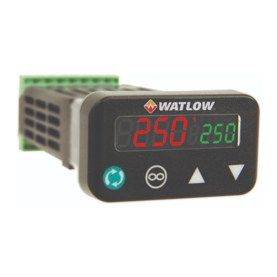
KEYPAD OVERVIEW

- Left Display: Home at beginning displays process value (PV). Entering into menus displays the value or setting of parameter
- Output Activity: Indicate activity of outputs 1 & 2, dio 5 & 6
- Manual Power: Indicates the set point is in % manual mode
- Right Display: Home at beginning displays set point (SP). Displays page name when entering pages. Entering into menus displays the parameter name
- Up and Down Keys:
At Home adjust the set point in right display. Changes menu inside pages. Inside menus, changes the selected setting in left display - Infinity Key: Clears or silence alarm when active else return home
- Advance Key: Advances through menu prompts.
 Scan for full manual. |
|
 +1-(507)-494-5656 wintechsupport@watlow.com
INTRODUCTION TO KEYPAD AND MENU BASICS
Pages, Menus and Keypad Basics
See Keyboard Overview
These instructions are not inclusive. This Quick Start Guide (QSG) is meant to be a quick reference to show you how to navigate to frequently used areas of the controller. As an example; setting process outputs are not documented in this QSG. Refer to the User's Guide for more detailed instructions.
Note: Diagrams might vary depending on programming the controller.
Introduction to the Operations & Setup Pages
Upon power up, the display will default to home. The left red displays process (PV). The right green displays set point (SP). Setup page is a collection of menus having parameters changed typically one time when controller is first installed or each time hardware changes occur. Operations page is a collection of menus having parameters changed more frequently.
Menus in each page contain common parameters that affect a particular function of the controller. Ex. Analog Input, Control Loop, Outputs and Alarms are commonly used functions. Parameters are grouped for each function. The Global function is where to set the display units between °F and °C. The Global function is where to set the display units between °F and °C. Set units first if using °C as default is °F.Setup Page

To enter the Setup Page, press both arrow key  for 6 seconds.
Use arrow keys to select menu.
Press advance key to enter selected Menu.
Press the Infinity key for 2 secs. at any point within the menu to return home.
Operations Page

To enter the Operations Page, press both arrow key for 3 seconds.
Use arrow keys to select menu.
Press advance keyto enter selected Menu.
Press the Infinity keyfor 2 secs. at any point within the menu to return home.
SET INPUTS

SET CONTROL LOOP

SET OUTPUTS

SET ALARM

SET ALARM SET POINTS

LOOP CONTROL MODE/LOOP SETPOINT
Set Loop Control Mode

Adjust Loop Set Point

AUTOTUNE THE CONTROL LOOP


Documents / Resources
References
Download manual
Here you can download full pdf version of manual, it may contain additional safety instructions, warranty information, FCC rules, etc.
Advertisement


Need help?
Do you have a question about the PM3 LEGACY and is the answer not in the manual?
Questions and answers