Table of Contents
Advertisement
1241 Bundy Boulevard., Winona, Minnesota USA 55987
Phone: +1 (507) 454-5300, Fax: +1 (507) 452-4507 http://www.watlow.com
0600-0066-0000 Rev. F
July 13, 2017
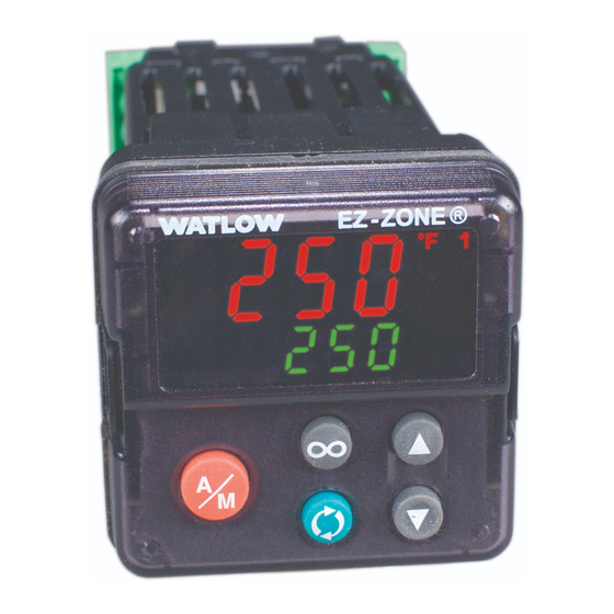
EZ-ZONE
User's Guide
L
I
M
I
T
RESET
Limit Controller
®
PM Express
RESET
L
I
M
I
T
L
I
M
I
T
RESET
TOTAL
CUSTOMER
SATISFACTION
3 Year Warranty
ISO 9001
Registered Company
Winona, Minnesota USA
Made in the U.S.A.
Advertisement
Table of Contents

Related Manuals for Watlow EZ-ZONE PM Series


Summary of Contents for Watlow EZ-ZONE PM Series
- Page 1 Limit Controller TOTAL CUSTOMER SATISFACTION 3 Year Warranty ISO 9001 Registered Company Winona, Minnesota USA 1241 Bundy Boulevard., Winona, Minnesota USA 55987 Phone: +1 (507) 454-5300, Fax: +1 (507) 452-4507 http://www.watlow.com 0600-0066-0000 Rev. F Made in the U.S.A. July 13, 2017...
-
Page 2: Safety Information
PM is manufactured by ISO 9001 registered processes and is backed by a three year warranty to the first purchaser for use, providing that the units have not been misapplied. Watlow's obligations hereunder, at Watlow's option, are limited to replacement, repair or refund of purchase price, and parts which upon examina- tion prove to be defective within the warranty period specified. -
Page 3: Technical Assistance
Technical Assistance You can get assistance from your local Watlow representative (see back cover), send an email with your ques- tions to: wintechsupport@watlow.com or dial +1 (507) 494-5656 between 7 a.m. and 5 p.m. Central Standard Time (CST) and ask for an Applications Engineer. Please have the following information available when calling: •... -
Page 4: Installation And Wiring
Installation and Wiring 1/32 DIN (PM3) Dimensions 15.9 mm (0.63 in) 101.6 mm (4.00 in) 53.3 mm 31.2 mm (2.10 in) (1.23 in) Side 30.9 mm (1.22 in) Front 1/32 DIN (PM3) Recommended Panel Spacing 44.96 to 45.47 mm (1.77 to 1.79 in) 22.2 to 22.5 mm (0.87 to 0.89 in) 21.6 mm... - Page 5 1/16 DIN (PM6) Dimensions 15.8 mm 53.3 mm (0.62 in) 101.6 mm (2.10 in) (4.00 in) 53.3 mm (2.10 in) Side Front 51.2 mm (2.02 in) 1/16 DIN (PM6) Recommended Panel Spacing 44.96 to 45.47 mm (1.77 to 1.79 in) 44.96 to 45.47 mm (1.77 to 1.79 in) 21.6 mm...
- Page 6 1/8 DIN (PM8) Vertical Dimensions 15.75 mm (0.62 in) 53.34 mm 1.52 mm (0.06 in) (2.10 in) 100.33 mm (3.95 in) 10.16 mm 54.8 mm (0.40 in) (2.16 in) 30.73 mm (1.21 in) 101.60 mm (4.00 in) 1/8 DIN (PM8) Vertical - Recommended Panel Spacing 44.96 to 45.60 mm (1.77 to 1.79 in) 92.00 to 92.80 mm...
- Page 7 1/8 DIN (PM9) Horizontal Dimensions 15.75 mm (0.62 in) 100.33 mm 1.52 mm (0.06 in) (3.95 in) 53.8 mm 53.34 mm (2.16 in) (2.10 in) 10.16 mm (0.40 in) 30.73 mm (1.21 in) 101.60 mm (4.00 in) 1/8 DIN (PM9) Horizontal Recommended Panel Spacing 92.00 to 92.80 mm (3.62 to 3.65 in) 44.96 to 45.6 mm...
- Page 8 Dimensions 1/4 DIN (PM4) Dimensions 15.75 mm (0.62 in) 100.33 mm 1.52 mm (0.06 in) (3.05 in) 100.33 mm (3.95 in) 12.70 mm (0.50 in) 30.73 mm (1.21 in) 100.84 mm (3.97 in) 92.00 to 93.0 mm (3.62 to 3.65 in) 92.00 to 93.0 mm (3.62 to 3.65 in) 21.6 mm...
-
Page 9: Installation
Installation the ridges on the sides of the controller. Each tooth is staggered at a different depth from the front so that only one of the tabs, on each side, is locked onto the ridges at a time. Removing the Mounted Controller from Its Case 1. -
Page 10: Terminal Definitions
Terminal Definitions Slot C Terminal Function Model power input: ac or dc+ PM _L_ _ _ - AAAAB _ _ power input: ac or dc- Standard Bus EIA-485 common PM _L_ _ _ - AAAAB _ _ Standard Bus EIA-485 T-/R- Standard Bus EIA-485 T+/R+ Slot A Input 1... - Page 11 Note: In the graphics below notice that the Slot A connector does not show labeling for the outputs. Labeling for Slot A outputs is based on the controller part number. CF CD CE Output 1 Output 2 EZ-ZONE PM Limit Express •...
- Page 12 Note: Ó Warning: Adjacent terminals may be labeled differently, de- pending on the model number. Use National Electric (NEC) or other country-specific standard wiring and safety practices when wiring and Note: connecting this controller to a power source and to To prevent damage to the controller, do not connect electrical sensors or peripheral devices.
- Page 13 Note: In the drawings below for each input notice that the Slot A connector labeling is identified. Note: When using a 2 wire RTD, jumper S1 and T1 together Inputs All inputs shown below represent input 1 (the only input) and are to be connected to slot A of the Limit Control. Process Thermocouple Volts...
-
Page 14: Open Collector
Outputs Please note all outputs are connected exclusively to slot A. Output availability is based on the part number of your Limit Control. Note: In the drawings below for each output notice that the Slot A connector labeling is identified with the corre- sponding part number below. - Page 15 Outputs (cont.) Switched DC • 22 to 32VÎ(dc) @ 30mA maximum supply current • short circuit limited to <50 mA • 22 to 32VÎ(dc) open circuit voltage • Use dc- and dc+ to drive external solid-state relay. • DIN-a-mite compatibility is for output 1 only. - single-pole: up to 4 in parallel or 4 in series - 2-pole: up to 2 in parallel or 2 in series - 3-pole: up to 2 in series...
-
Page 16: Keys And Displays
Keys & Displays 16 DIN LIMIT Controller Upper Display: Zone Display: On power up, displays Temperature Units Indicator When [2onE] (found in the the process value, otherwise Lights: Factory Page) is set to on, indicates displays the value of the Indicates whether the tempera- the controller zone. -
Page 17: Responding To A Displayed Message
Keys & Displays for 1/8 or 1/4 DIN PID Controllers ® RESET ® ® RESET Responding to a Displayed Message An active message will cause the display to toggle [AL; E 1] Alarm 1 Error (alarm state cannot be deter- between the normal settings and the active message mined due to lack of sensor input) in the upper or left display and [Attn] in the lower... -
Page 18: Operations Menu
Upon power up of the control, Operations Menu using the advance key will scroll through the various prompts found in the Operations Menu. At any Display Parameter Name Description point within the Operations menu to return to the default display push Limit Low Set Point [`LL;... - Page 19 Range Defaults are shown bold -1,999.000 to 9,999.000°F or units -1,128.000 to 5,537.000°C Units, 32°F or 0°C -1,999.000 to 9,999.000°F or units -1,128.000 to 5,537.000°C Units, 300°F or 150°C -1,999.000 to 9,999.000°F or units -1,128.000 to 5,537.000°C Units, 32.0°F or 0.0°C -1,999.000 to 9,999.000°F or units -1,128.000 to 5,537.000°C Units, 300.0°F or 150.0°C...
-
Page 20: Setup Menu
To enter the Setup Menu push and hold Setup Menu the up and down arrow keys for ap- proximately 3 seconds. Once there, push Display Parameter Name Description the green advance key to scroll through to the prompt of choice and then use [LoC] Lockout Menu the up and down arrow keys to change... - Page 21 Range (Defaults are shown bold) 1 to 5 1 Operations Menu (read only)* 2 Operations Menu (Set point R/W)* 3 Operations Menu (Set point R/W, Control Mode R/W)* 4 Operations Menu R/W access)* 5 Operations Menu and Setup Menu full R/W access *You can change the security level at any level [``tC] Thermocouple [`MA] Milliamps dc...
- Page 22 To enter the Setup Menu push and hold Setup Menu (cont.) the up and down arrow keys for ap- proximately 3 seconds. Once there, push Display Parameter Name Description the green advance key to scroll through to the prompt of choice and then use Limit Set Point - Range High [`r;...
- Page 23 Range (Defaults are shown bold) -1,999.00 to 9,999.000 °F or Units -1,110.555 to 5,537.000 °C [`oFF] Off, [LiM] Limit*, [ALM] Alarm *Note: Switched DC/Open Collector option should only be used to control an external mechanical relay if Limit function is selected. [`LiM] Limit [both] Both [high] High...
-
Page 24: Alarm Silencing
To enter the Setup Menu push and hold Setup Menu (cont.) the up and down arrow keys for ap- proximately 3 seconds. Once there, push Display Parameter Name Description the green advance key to scroll through to the prompt of choice and then use Alarm Latching [`A;... - Page 25 Range (Defaults are shown bold) [nLAt] Non-Latching [`LAt] Latching [`oFF] Off [`Str] Startup [StPt] Set Point [both] Both [`oFF] Off [``on] On [`oFF] Off [``on] On [AC; P u] Active Process Value [none] None [`Ls; t ] Limit State [`Lh; S ] Limit High Set Point [`LL;...
-
Page 26: Specifications
Specifications Line Voltage/Power • All voltage levels represent minimums and maximums • 85 to 264V~(ac), 47 to 63Hz • 20 to 28VÅ(ac), +10/-15 percent; 50/60Hz, ±5 percent • 12 to 40VÎ(dc) • 10VA maximum power consumption (PM3 and PM6) • 14VA maximum power consumption (PM4, 8 and 9) •... - Page 27 Specifications (cont.) Thermistor Input (Not included with Universal Input) Thermistor Input Max Error Accuracy Accuracy Input Type Units @ 25 Deg C Range Low Range High Thermistor, 5K range ±5 5000 Ohms Thermistor, 10K range ±10 10000 Ohms Thermistor, 20K range ±20 20000 Ohms...
- Page 28 Additional Options (Digits #13 and #14) AA = Standard EZ-ZONE face plate XX = Custom firmware,overlays,parameters settings AB = EZ-ZONE logo and no Watlow name AC = No logo and no Watlow name AG = Conformal coating EZ-ZONE PM Limit Express •...
- Page 29 EZ-ZONE PM Limit Express • 29 •...
-
Page 30: How To Reach Us
Linby, Nottingham, NG15 8AA Postfach 11 65, Lauchwasenstr. 1 Latin America United Kingdom D-76709 Kronau Telephone: (0) 115 964 0777 Watlow de México S.A. de C.V. Germany Fax: (0) 115 964 0071 Av. Fundición No. 5 Tel: +49 (0) 7253 9400-0 Email: info@watlow.co.uk Col.
Need help?
Do you have a question about the EZ-ZONE PM Series and is the answer not in the manual?
Questions and answers