Table of Contents
Advertisement
Quick Links
PM3
TOTAL
CUST T O O M M ER
CUS
ER
S S A A TISF
TISFA A CTI
CTIO O N N
3 Year Warranty
Phone: +1 (507) 454-5300, Fax: +1 (507) 452-4507 http://www.watlow.com
10-42073 Rev. -, July 2020
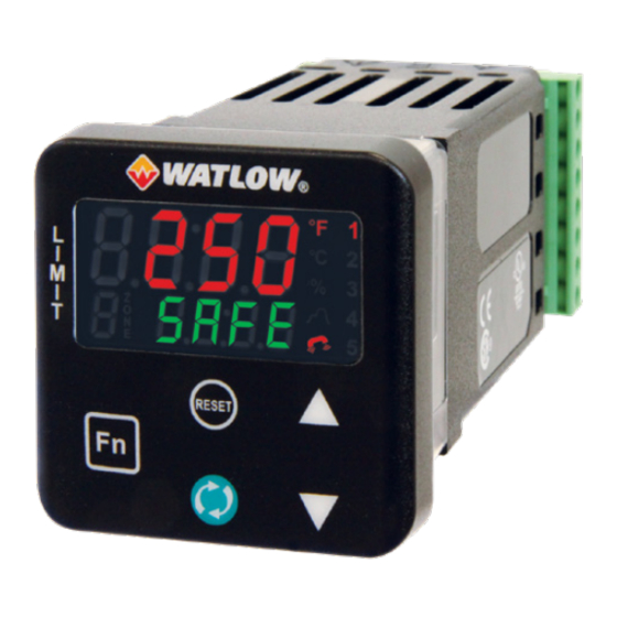
Express Limit Controller
User Guide
/
DIN
1
32
Available Soon
For Configurations:
PM(3,6)L _ _ _ - _ AAA H_ _
1241 Bundy Boulevard., Winona, Minnesota USA 55987
PM6
Made in the U.S.A.
ISO 9001
ISO 9001
Registered Company
Winona, Minnesota USA
Advertisement
Table of Contents

Related Manuals for Watlow PM LEGACY PM3


Summary of Contents for Watlow PM LEGACY PM3
- Page 1 TISFA A CTI CTIO O N N 3 Year Warranty Registered Company Winona, Minnesota USA 1241 Bundy Boulevard., Winona, Minnesota USA 55987 Phone: +1 (507) 454-5300, Fax: +1 (507) 452-4507 http://www.watlow.com 10-42073 Rev. -, July 2020 Made in the U.S.A.
- Page 2 1. If you are an End User, and this PM is installed in an OEM System, please contact the OEM to get the PM repaired. If you are an OEM or Watlow Distributor, please go to www.watlow.com/ rma to start the RMA process. Watlow Customer Service will then respond back with the RMA number via an email.
-
Page 3: Table Of Contents
CE Declaration of Conformity ..................... Bluetooth Enabled Product Statement ................Available PM LEGACY™ Series Literature and Resources Contact Watlow Directly: For technical assistance contact Watlow at: www.watlow.com Or call at: 1-800-WATLOW2 Or (1-800-928-5692) Or email at: wintechsupport@watlow.com PM6 LEGACY™ Express... -
Page 4: Safety Instructions
Safety Information We use note, caution and warning symbols throughout this book to draw your attention to impor- tant operational and safety information. A “NOTE” marks a short message to alert you to an important detail. A “CAUTION” safety alert appears with information that is important for protecting your equip- ment and performance. -
Page 5: Overview
Overview A Conceptual View of the PM The flexibility of the PM software and hardware allows for a large range of configurations. Acquiring a better understanding of the controller’s overall functionality and capabilities while at the same time planning out how the controller can be used will deliver maximum effectiveness in your application. - Page 6 (Overview Continued) Outputs The Output Wire Terminals are located on Internal Functions the back side of the controller. See Figure 3. The controller will use input signals to calculate The Outputs properly wired and configured a value and then perform an operation. A sam- can perform various functions or actions in ple of some functions may be as simple as: response to information provided by a function...
-
Page 7: Feature And Benefits
• Simplifies switching between products • Speeds up user’s system documentation • Enables simple, one-touch operation of user-defined, repetitive activities Three-Year Warranty • Demonstrates Watlow’s reliability and Touch-Safe Package product support • Increases installer and operator safety • Complies with IP2X requirements... -
Page 8: Installation
Installation Mounting Screw Mounting Panel PM6 Controller Figure 1: PM6 Installation For a PM3 Controller, make the panel cutout using the measurements shown on page 9. For a PM6 Controller, make the panel cutout using the measurements shown on Figure 2: Slide Mounting Bracket over page 10. -
Page 9: Wiring Diagrams
Installation and Wiring 1/32 DIN (PM3) Dimensions 2.10in 0.40in 53.3mm 10.2mm 1.22in 30.9mm 1.38in 35.2mm Mounting Panel 4.22in 107.2mm 1/32 DIN (PM3) Recommended Panel Spacing 45.2 mm (1.78 in) 22.4 mm (0.88 in) 21.6 mm panel thickness 1.53 to 9.52 mm (0.060 to (0.85 in) 0.075 in) 21.6... - Page 10 1/16 DIN (PM6) Dimensions 2.10 0.40 53.34 10.16 2.10 53.34 1.38 35.16 4.22 Mounting Panel 107.18 1/16 DIN (PM6) Recommended Panel Spacing 45.2 mm (1.78 in) 45.2 mm (1.78 in) 21.6 mm panel thickness 1.53 to 9.52 mm (0.060 to (0.85 in) 0.075 in) 21.5 mm...
-
Page 11: Terminal Definitions
Terminal Definitions Slot C Terminal Function Model power input: ac or dc+ PM6L _ _ _ - _ AAA H_ _ power input: ac or dc- Standard Bus EIA-485 common PM6L _ _ _ - _ AAA H_ _ Standard Bus EIA-485 T-/R- Standard Bus EIA-485 T+/R+ Slot A Input 1... - Page 12 Note: In the graphics below notice that the Slot A connector does not show labeling for the outputs. Labeling for Slot A outputs is based on the controller part number. CF CD CE Output 1 Output 2 Ó Warning: Note: Use National Electric (NEC) or other country- Maximum wire size termination and torque specific standard wiring and safety practices...
- Page 13 Note: In the drawings below for each input notice that the Slot A connector labeling is identified. Note: When using a 2 wire RTD, jumper S1 and T1 together Inputs All inputs shown below represent input 1 (the only input) and are to be connected to slot A of the Limit Control.
- Page 14 Outputs Please note all outputs are connected exclusively to slot A. Output availability is based on the part number of your Limit Control. Note: In the drawings below for each output notice that the Slot A connector labeling is identified with the corresponding part number below.
- Page 15 Outputs (cont.) Switched DC • Supplied current up to a maximum of 30 mA. See Power Supply note above. • Short circuit limited to <50 mA • 22 to 32V (dc) open circuit voltage • Use dc- and dc+ to drive external solid-state relay •...
-
Page 16: Keys And Display Descriptions
Keys & Displays 16 DIN LIMIT Controller Upper Display: Temperature Units Zone Display: On power up, displays Indicator Lights: When [2onE] (found in the the process value, otherwise Indicates whether the Factory Page) is set to on, indi- displays the value of the temperature is displayed in cates the controller zone. -
Page 17: Menu And Keypad Basics
Menu and Keypad Basics Operations Menu NOTE: You must read and understand the role of each key on your controller keypad before proceed- ing. Refer to the drawing and callouts on the previous s] Limit Low Set Point [`L; L page. -
Page 18: Operations Menu
Upon power up of the control, using Operations Menu the advance key will scroll through the various prompts found in the Display Parameter Name Description Operations Menu. At any point within the Operations menu to return to Limit Low Set Point [`LL;... -
Page 19: Setup Menu
To enter the Setup Menu push and hold Setup Menu the up and down arrow keys for ap- proximately 3 seconds. Once there, push Display Parameter Name Description the green advance key to scroll through to the prompt of choice and then use the [LoC] Lockout Menu up and down arrow keys to change the... - Page 20 To enter the Setup Menu push and hold Setup Menu (cont.) the up and down arrow keys for ap- proximately 3 seconds. Once there, push Parameter Name Description Display the green advance key to scroll through to the prompt of choice and then use Resistance Range [``r;...
- Page 21 To enter the Setup Menu push and hold Setup Menu (cont.) the up and down arrow keys for ap- proximately 3 seconds. Once there, push Display Parameter Name Description the green advance key to scroll through to the prompt of choice and then use Function of Output 1 [`fn1] the up and down arrow keys to change...
- Page 22 To enter the Setup Menu push and hold Setup Menu (cont.) the up and down arrow keys for ap- proximately 3 seconds. Once there, push Display Parameter Name Description the green advance key to scroll through to the prompt of choice and then use Alarm Hysteresis [`A;...
- Page 23 To enter the Setup Menu push and hold Setup Menu (cont.) the up and down arrow keys for ap- proximately 3 seconds. Once there, push Display Parameter Name Description the green advance key to scroll through to the prompt of choice and then use Alarm Silencing [`A;...
-
Page 24: Specifications
Specifications Controller Line Voltage/Power • User selectable heat/cool, on-off, P, PI, • 85 to 264VAC, 47 to 63Hz PD, PID or alarm action, not valid for limit • 20 to 28VAC, +10/-15%; 50/60Hz, ±5% controllers • 12 to 40VDC • Auto-tune with control algorithm •... - Page 25 Specifications (Continued) Output Hardware Operator Interface • Switched dc = 22 to 32VDC @ 30mA • Dual 4 digit, 7 segment LED displays • Open collector = 30VDC max. @ 100mA • Typical display update rate 1Hz max. current sink •...
-
Page 26: Ordering Information
Limit controller with universal input PM LEGACY™ EXPRESS Limit Version Custom Options 13-14 Power Supply, Digital Inputs/Outputs WP = Watlow logo face plate 100 to 240VAC No logo/no name face plate WN = 20 to 28VAC or 12 to 40VDC Conformal coating... -
Page 27: Ce Declaration Of Conformity
Declaration of Conformity - Series EZ-ZONE ® WATLOW Electric Manufacturing Company 1241 Bundy Blvd. Winona, MN 55987 USA Declares that the following product meets the essential requirements of the following European Union Directives by using the relevant standards show below to indicate compliance. -
Page 28: Bluetooth Enabled Product Statement
Bluetooth Enabled Product Statement Bluetooth® Enabled Product Models PM6XXX‐(B, E, F, G, H or K)XXXXXX contain an embedded Bluetooth module. Output Power: Frequency Range 2402.0 ‐ 2480.0 Output Power 0.001 Watts Antenna gain: ‐0.6 dBi PCB antenna FCC The transmitter module is mounted on the top of the display PC board partially under the LED display module. Visible when display removed from bezel. Module FCC ID: VPYLBZY Part 15C 2. Unit is assembled from tested components, complete system not tested. NOTE: This equipment has been tested and found to comply with the limits for a Class B digital device, pursuant to Part 15 of the FCC Rules. These limits are designed to provide reasonable protection against harmful interference in a residential installation. This equipment generates, uses and can radiate radio frequency energy and, if not installed and used in accordance with the instructions, may cause harmful interference to radio communications. However, there is no guarantee that interference will not occur in a particular installation. If this equipment does cause harmful interference to radio or television reception, which can be determined by turning the equipment off and on, the user is encouraged to try to correct the interference by one or more of the following measures: ‐‐ Reorient or relocate the receiving antenna. ‐‐ Increase the separation between the equipment and receiver. ‐‐ Connect the equipment into an outlet on a circuit different from that to which the receiver is connected. ‐‐ Consult the dealer or an experienced radio/TV technician for help. Industry Canada Contains IC: 772C‐LBZY Specification : RSS210 ... - Page 29 PM3/PM6 LEGACY™ Express Limit • 2 9 •...
- Page 30 1241 Bundy Boulevard., Winona, Minnesota USA 55987 Phone: +1 (507) 454-5300, Fax: +1 (507) 452-4507 http://www.watlow.com PM3/PM6 LEGACY™ Express Limit • 3 0 •...
Need help?
Do you have a question about the PM LEGACY PM3 and is the answer not in the manual?
Questions and answers