
Related Manuals for Eaton EASY222-DN


Summary of Contents for Eaton EASY222-DN
- Page 1 09/10 MN05013007Z-EN User Manual replaces 10/04 AWB2528-1427GB EASY222-DN DeviceNet Slave Interface...
- Page 2 2008, edition date 02/08 edition 2010, edition date 09/10 See revision protocol in the “About this manual“ chapter © 2002 by Eaton Industries GmbH, 53105 Bonn Production: Thomas Kracht, Barbara Petrick Translation: Terence Osborn All rights reserved, including those of the translation.
- Page 3 Danger! Dangerous electrical voltage! Before commencing the installation • Disconnect the power supply of the device. • Suitable safety hardware and software measures should be implemented for the • Ensure that devices cannot be accidentally I/O interface so that a line or wire breakage restarted.
- Page 4 • Measures should be taken to ensure the • Wherever faults in the automation system proper restart of programs interrupted may cause damage to persons or property, after a voltage dip or failure. This should external measures must be implemented to not cause dangerous operating states even ensure a safe operating state in the event for a short time.
-
Page 5: Table Of Contents
System overview Structure of the unit EASY222-DN Communication profile Hardware and operating system requirements Improper use Installation EASY222-DN connection to the basic unit Connecting the power supply Connecting DeviceNet – Terminal assignment DeviceNet – Terminal resistors EMC-conformant wiring of the network Potential isolation Data transfer rates –... - Page 6 09/10 MN05013007Z-EN Contents Cycle time of the "easy" basic unit EDS file DeviceNet functions Object model – Identity object – DeviceNet object – easy Object DeviceNet Communication profile – I/O Messages – Explicit Messages Direct data exchange with easy/MFD (Polled I/O Connection) Input data: Mode, S1 –...
- Page 7 09/10 MN05013007Z-EN Contents – Timing relays T1 – T8: read actual value (timing range, actual value, switching function) 82 – Timing relays T1 – T8: write parameters (timing range, reference value,switching function)86 Ö Ö – Time switch 1 – 4: read actual value (channel, ON time, OFF time) Ö...
- Page 8 09/10 MN05013007Z-EN Contents easy800/MFD control commands Data exchange procedure Version history Read/write date and time – Winter/summer time, DST Read/write image data – Overview – Local analog inputs: IA1 – IA4 – Local diagnostics: ID1 – ID16 – Read local inputs: IW0 –...
- Page 9 09/10 MN05013007Z-EN Contents – Conditional jump JC01…JC32 – Value scaling: LS01 – LS32 – Master Reset: MR01 – MR32 – Data Multiplexer MX01…MX32 – Numerical Converter: NC01 – NC32 – Hours-run Counter: OT01 – OT04 – Pulse width modulation: PW01 – PW02 –...
- Page 10 09/10 MN05013007Z-EN Contents...
-
Page 11: About This Manual
• "easy800 control relays" (MN04902001Z-EN; previous description AWB2528-1423GB) • "MFD-Titan multi-function display" (MN05002001Z-EN; previous description AWB2528-1480GB). All manuals are available on the Internet for download as PDF files. They can be quickly located at http://www.eaton.com/moeller h Support by entering the "EASY222-DN" as the search term. -
Page 12: References
09/10 MN05013007Z-EN About This Manual References [1] DeviceNet Specification Volume I Release 2.0, Errata 1 - 4 April 1, 2001 [2] DeviceNet Specification Volume II Release 2.0, Errata 1 - 4 April 1, 2001 Device designation The following short names for equipment types are used in this manual, as far as the description applies to all of these types: •... - Page 13 09/10 MN05013007Z-EN Device designation • easy-DC for – easy6…-DC-… – EASY719-DC-… – EASY8…-.DC-… • easy-DA for – EASY719-DA... • MFD-CP8… for – MFD-CP8-ME – MFD-CP8-NT – MFD-AC-CP8-ME – MFD-AC-CP8-NT • MFD-CP10… for – MFD-CP10-ME – MFD-CP10-NT • MFD-…-CP8/CP10 for – MFD-CP8-ME –...
-
Page 14: Abbreviations And Symbols
09/10 MN05013007Z-EN About This Manual Abbreviations and Meaning of abbreviations and symbols used in this manual: symbols Binary Coded Decimal code Controller Area Network Decimal (number system based on 10) Hexadecimal (Number system based on 16) Length MAC ID Media Access Control Identifier ODVA Open DeviceNet Vendor Association Personal Computer... -
Page 15: The Easy222-Dn
The EASY222-DN communication module has been devel- oped for automation tasks with the DeviceNet field bus. EASY222-DN acts as a “gateway” and can only be operated in conjunction with the expanded easy600, easy700, easy800 or MFD basic units. The system unit consists of the... -
Page 16: System Overview
The easy DeviceNet slaves are integrated into a DeviceNet fieldbus system. Figure 1: Implementation of EASY222-DN in the DeviceNet a Master area, PLC (e.g.: SLC 500) or PC with CAN card b Slave area, e.g.: Control relay easy/MFD with DeviceNet inter-... -
Page 17: Structure Of The Unit
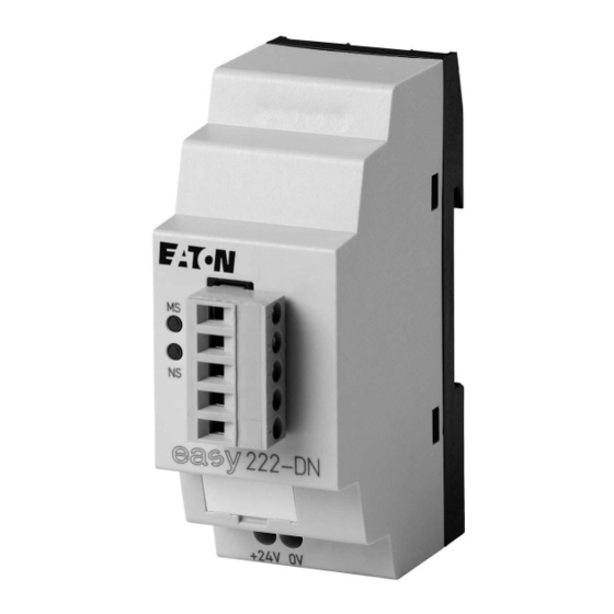
09/10 MN05013007Z-EN Structure of the unit Structure of the unit Figure 2: Surface Mounting EASY222-DN a easyLink socket b 5-pin DeviceNet connection to ODVA c Power supply 24 V H d Device label e Network Status LED NS f Module Status LED MS... -
Page 18: Easy222-Dn Communication Profile
09/10 MN05013007Z-EN The EASY222-DN EASY222-DN Communica- • Predefined master/slave communication settings tion profile – The I/O polling connection is used for the transfer of 3 bytes of input data (R1 to R16) and 3 bytes of output data (S1 to S8) between the easy base unit with gateway interconnection and the DeviceNet PLC. -
Page 19: Hardware And Operating System Requirements
09/10 MN05013007Z-EN Hardware and operating system requirements Hardware and operating The EASY222-DN expansion unit operates together with the system requirements easy600, easy700, easy800 and MFD basic units from the following operating systems: Basic unit EASY222-DN expansion unit Device version OS version... -
Page 20: Improper Use
09/10 MN05013007Z-EN The EASY222-DN Improper use "easy" may not be used to replace safety-relevant control circuits, e.g.: • burner, • Emergency switching off, • crane controls or • two-hand safety controls. -
Page 21: Installation
09/10 MN05013007Z-EN Installation Applicable are the same guidelines as for easy/MFD basic units with expansion modules. EASY222-DN connection to the basic unit Figure 3: Mounting the EASY222-DN on the basic unit Installation Removal... -
Page 22: Connecting The Power Supply
EASY8… MFD-CP8… Figure 4: Connection between basic unit and EASY222-DN Connecting the power EASY222-DN operates with a 24 V DC supply voltage supply (a section “Current supply”, page 257). Danger! Ensure a reliable electrical isolation of the low voltage (SELV) for the 24 V supply. -
Page 23: Connecting Devicenet
All pins of the plug must be connected to ensure safe communication of the on the fieldbus Devi- EASY222-DN ceNet. This also applies to the 24-V bus voltage. The gateway therefore does not participate in communica- tion on the bus if the bus voltage is not available. -
Page 24: Terminal Resistors
09/10 MN05013007Z-EN Installation Terminal resistors The first and last node of a DeviceNet network must be terminated by means of a 120 O bus termination resistor. This device is interconnected between the CAN_H and CAN_L terminals..Figure 7: Terminating resistors R : CAN_H and CAN_L... -
Page 25: Potential Isolation
ZB4-102-KS1 Figure 9: Shielding connection to the mounting plate Potential isolation The following potential isolation specifications apply to EASY222-DN interfaces: + – Figure 10: Potential isolation between supply voltage and outputs a Safe electrical isolation between easyLink and the 240 V AC... -
Page 26: Data Transfer Rates - Automatic Baud Rate Detection
09/10 MN05013007Z-EN Installation Data transfer rates – After it is switched on, the EASY222-DN module automati- automatic baud rate cally detects the data transfer rate of the communication detection network. However, this is possible only if at least one network node transmits valid message frames. The device... -
Page 27: Device Operation
“Operational” status, the state of the GW changes to static even on the devices with a flashing GW, a section “Network status LED” on page 28). If the EASY222-DN has factory settings (node ID = 127), you need to define the DeviceNet slave address. -
Page 28: Devicenet Setting The Slave Address
PLC (possibly by means of an explicit message). Setting the address at the basic unit with display: Basic requirements: • The respective basic devices (easy600, easy700, easy800 or MFD-Titan) and EASY222-DN are supplied with voltage. • The basic unit is accessible (password protection not acti- vated). - Page 29 09/10 MN05013007Z-EN DeviceNet setting the slave address Confirm with OK. Select the LINK..menu with the easy800/MFD units NET... LINK... Confirm with OK. The DEVICENET menu appears. Set the address by means of the cursor buttons: Í Ú DEVICENET – Set the current numeric value via the keys.
-
Page 30: Setting The Address By Means Of Easysoft
The following applies for device version identity 01: After you have changed the MAC ID via the basic device you must restart EASY222-DN. To do this switch the power supply off and on again. EASY222-DN devices with a version ID > 01 take on the address automatically. -
Page 31: Led Status Indication
EASY222-DN monitors itself as well as the DeviceNet communication bus. Module status LED The dual-color LED (GREEN/RED) indicates the status of EASY222-DN. It monitors whether the device is fully func- tional and operates without fault. No power supply at the EASY222-DN. GREEN flashing EASY222-DN is in standby mode. -
Page 32: Network Status Led
The dual-color LED (GREEN/RED) indicates the status of the DeviceNet communication bus. This function monitors oper- ability and correct operation of the EASY222-DN. EASY222-DN is offline. Either it is performing a DUP_MAC_ID test or power is missing at the device or bus. -
Page 33: Cycle Time Of The "Easy" Basic Unit
Cycle time of the "easy" Network traffic between the easy/MFD basic unit and the basic unit EASY222-DN via easyLink extends the cycle scan time of the basic device In the worst case, this time can be extended by 25 ms. - Page 34 09/10 MN05013007Z-EN...
-
Page 35: Devicenet Functions
Profile according to ODVA specifications (Release V2.0). The DeviceNet object model can be used to describe all EASY222-DN functions. The object model reflects the prin- ciple of communication at the application layer. This manual deals in the following only with objects relevant for your application. - Page 36 09/10 MN05013007Z-EN DeviceNet functions The DeviceNet objects in the illustration can be compiled again as “Management objects”, “Connection objects” and “Manufacturer-specific objects”. Their tasks will be briefly explained after the following. Object address Service Function address Class ID Instance ID Attribute ID [hex] [hex]...
- Page 37 09/10 MN05013007Z-EN Object model Management objects These define DeviceNet-specific data and functions and must be supported by all DeviceNet devices: • Identity Object The Identity Object (Class ID 01 ) contains all data for unique identification of a network node, e.g. the Vendor ID, Device Type and Product Code.
- Page 38 09/10 MN05013007Z-EN DeviceNet functions Manufacturer-specific objects Define device-specific data and functions (Application Objects, Parameter Object, Assembly Object). • Application Objects – easy Object Application objects (Class ID: 64 ) describe simple applica- tions for automation engineering. They are either predefined in the DeviceNet object library or by the user.
-
Page 39: Identity Object
Read Serial The serial number of the device can be read number with this attribute. Read Product The product name EASY222-DN is stored as name an ASCII value (hex). Read Configura- This attribute returns a counter value that tion consis-... - Page 40 Service code Service code Service name Description value Reset Calls the Reset function of the EASY222-DN communica- tion module. Get_Attribute_Single This service can be used to fetch the value of a selected attribute from the communication module. Set_Attribute_Single This service can be used to set a selected attribute in the...
-
Page 41: Devicenet Object
Service code a table 3 a table 2 The DeviceNet object instance is used to configure the EASY222-DN communication module and to define the physical environment. The same Service Codes are used as for the Identity Object. Table 3: Attribute IDs of the DeviceNet Object instance... -
Page 42: Easy Object
09/10 MN05013007Z-EN DeviceNet functions easy Object Object address Function Access Class ID Instance ID Attribute ID Service code a table 4 a table 5 The easy object can be used to access easy/MFD functions via the DeviceNet communication bus. The table below shows the attributes supported by this object. - Page 43 Predefined This attribute is used to predefine the Write Outputs output data (R data) that the EASY222-DN device indicates on power up. The struc- ture of these 3 bytes is described in detail under Section “Output data: mode, R1 –...
- Page 44 Static value. (attribute ID 1) Coupling module status The basic unit is connected with the EASY222-DN (attribute ID 2) gateway via the easyLink. The basic device is not switched on or not connected with the EASY222-DN gateway via the easyLink.
-
Page 45: Devicenet Communication Profile
09/10 MN05013007Z-EN DeviceNet Communication profile DeviceNet Communication DeviceNet is based on a connection-oriented communication profile model. This means that the data can always only be exchanged via the specific connections assigned to the devices. DeviceNet stations communicate either by means of I/O messages or explicit messages. -
Page 46: Explicit Messages
09/10 MN05013007Z-EN DeviceNet functions Explicit Messages Explicit messages are used to transfer low-priority configura- tion data, general management data or diagnostics data between two specific devices. This is always a point-to-point connection in a client/server system, which means that a response must always be issued by the server after a request from a client. - Page 47 PLC program for the execution of the control commands (Explicit Messages). The application note AN2700K17G supports the control commands of EASY222-DN. It provides subroutines in the program for controlling the required “Explicit Messages”, i.e. the programming is replaced by the call and the parameter assignment of the subroutine.
- Page 48 • The significance of the message is defined in the system with the message ID. The world of the DeviceNet provides four message groups. The EASY222-DN uses message group 2. This group uses 512 CAN identifiers (400 – 5FF ). Most messages Ids of this group are optionally defined for using the Predefined Master/Slave Connection Sets.
- Page 49 (a section “Read/write date and time” on page 101). The EASY222-DN communication module has the MAC ID = 3. It must be taken into account with the data sequence that the access is implemented in fragmented form.
- Page 50 09/10 MN05013007Z-EN DeviceNet functions Description Lengt DeviceNet – Byte (hex) (hex) Master sends a request (hex) with: 80 00 32 64 01 93 05 00 Byte 2 - service code = 32 DeviceNet Byte 3 - CLASS ID = 64 specific Byte 4 - Instance ID = 01 Byte 5 - Attribute ID = 93...
-
Page 51: Direct Data Exchange With Easy/Mfd (Polled I/O Connection)
– Scanning the output states of the easy/MFD – Scanning the mode of the easy/MFD. In order to transfer data between the slave EASY222-DN and a DeviceNet master control, you must map the respective cyclic data to the respective slave configuration. - Page 52 09/10 MN05013007Z-EN Direct data exchange with easy/MFD (Polled I/O Connection) The terms “input data” and “output data” are used rela- tive to the point of view of the DeviceNet master. DeviceNet master Outputs Inputs Write: Read: Output data Input data easy/MFD Inputs Outputs...
-
Page 53: Input Data: Mode
Input data: Attribute ID: 3 Mode, S1 – S8 The cyclic data transfer between DeviceNet master and the EASY222-DN slave is provided by the input data byte 0, 1 and 2. Table 7: Byte 0 to 2: input data, mode... - Page 54 09/10 MN05013007Z-EN Direct data exchange with easy/MFD (Polled I/O Connection) Table 9: Byte 1: Status of the easy/MFD outputs S1 to S8 easy/MFD 0 = status "0“ 1 = status "1" Example: Value 19 = 00011001 S5, S4 and S1 are active Byte 2: not used If control commands and I/O data are used at the same time:...
-
Page 55: Output Data: Mode
Output data: Attribute ID: 4 mode, R1 – R16 The cyclic data transfer between DeviceNet master and the EASY222-DN slave is provided by the output data byte 0, 1 and 2. Table 10: Byte 0 to 2: output data, mode... - Page 56 09/10 MN05013007Z-EN Direct data exchange with easy/MFD (Polled I/O Connection) Value 44 = 01000100 This value sets the "easy" status from RUN to STOP. It is also used only as command and is therefore based on the same operating principle as the RUN command. Value 00 = 00000000 If this value is written to the control byte, the gateway over-...
- Page 57 09/10 MN05013007Z-EN Output data: mode, R1 – R16 Table 12: Byte 1: Setting/resetting of the easy/MFD inputs R9 to easy/MFD 0 = status "0“ 1 = status "1" Example: Value 19 = 00011001 Enable R13, R12 and R9.
- Page 58 09/10 MN05013007Z-EN Direct data exchange with easy/MFD (Polled I/O Connection) Table 13: Byte 2: Setting/resetting of the easy/MFD inputs R1 to easy/MFD input 0 = status "0“ 1 = status "1" Example: Value 2B = 0010 1011 Enables R6, R4, R2 and R1. If control commands and I/O data are used at the same time: •...
-
Page 59: Control Commands For Easy600
09/10 MN05013007Z-EN Control commands for easy600 Control commands can be used to initiate data exchange for special services: • „Read and write date and time, summer and winter time“ (page 57) • „Read image data“ (page 61) • „Read/write function blocks“ (page 72). For this the message transfer protocol of the explicit messages is accessed in the master controller. - Page 60 09/10 MN05013007Z-EN Control commands for easy600 The operating mode of the basic unit must correspond with the status indicated at the LEDs when the various parameters are being set. In the communication between the stations, the master initi- ates the data exchange with a control command. The slave always gives a response to the request.
-
Page 61: Read And Write Date And Time, Summer And Winter Time
09/10 MN05013007Z-EN Read and write date and time, summer and winter time Read and write date and time, summer and winter time Telegram structure Byte Meaning Value (hex), sent by Master Slave 7 6 5 4 3 2 1 0 Attribute ID Read –... - Page 62 09/10 MN05013007Z-EN Control commands for easy600 Table 14: Byte 0 (master) or byte 1 (slave): weekday (value range 00 to 06) Day of week Monday = 00 Tuesday = 01 Wednesday = 02 Thursday = 03 Friday = 04 Saturday = 05 Sunday = 06 Table 15: Byte 1 (master) or byte 2 (slave):...
- Page 63 09/10 MN05013007Z-EN Read and write date and time, summer and winter time Table 16: Byte 2 (master) or byte 3 (slave): minute (value range 00 to 59) Value (bcd) Value 10 Value 1 … … … … Table 17: Byte 3 (master) or byte 4 (slave): winter/summer time (value range 00 to 01) Value (bcd) Value 10...
- Page 64 09/10 MN05013007Z-EN Control commands for easy600 Example: It is Friday, the current time-of-day is set to CET summer time, 14:36 p.m. . Byte Meaning Value (hex), sent by Master Slave 7 6 5 4 3 2 1 0 Attribute ID Write –...
-
Page 65: Read Image Data
09/10 MN05013007Z-EN Read image data Read image data General information on working with image data Systemecke Abbilddaten Abbilddaten werden werden geschrieben geschrieben easy/MFD Programmzyklus Interrupt-Funktion (0 ... 20 ms) easyLink (alle 12 bzw. 25 ms) When writing the image data, it must be taken into account that an image used in the easy/MFD program (e.g. -
Page 66: Digital Inputs, P Buttons And Operating Buttons
09/10 MN05013007Z-EN Control commands for easy600 Digital inputs, P buttons and operating buttons Using the following command the logical states of the digital button inputs P1 to P4 as well as the logical states of the digital inputs I1 to I16 can be read. The status of the P buttons is only displayed if •... - Page 67 09/10 MN05013007Z-EN Read image data Table 18: Byte 1: status inputs I1 to I8 Value Value 0 = switched off, Value 1 = switched on Table 19: Byte 2: status inputs I9 to I16 Value Value 0 = switched off, Value 1 = switched on...
- Page 68 09/10 MN05013007Z-EN Control commands for easy600 Table 20: Byte 3: Status of pushbuttons Meaning Status P1 Status P2 Status P3 Status P4 ESC not actuated/actuated OK not actuated/actuated DEL not actuated/actuated ALT not actuated/actuated Example: Value 01 = 00000001 í P1 active –...
-
Page 69: Analog Inputs: I7 - I8
09/10 MN05013007Z-EN Read image data Analog inputs: I7 – I8 The values of both analog inputs I7, I8 (only EASY...-DC-..) are read with the following command. Byte Meaning Value (hex), sent by Master Slave 7 6 5 4 3 2 1 0 Attribute ID Read –... -
Page 70: Timing Relays, Counter Relays, Timer Switch, Analog Value Comparator
09/10 MN05013007Z-EN Control commands for easy600 Timing relays, counter relays, timer switch, analog value comparator The following command reads the logic state of all timing relays, counters, time switches and analog value compara- tors. Telegram structure Byte Meaning Value (hex), sent by Master Slave 7 6 5 4 3 2 1 0... - Page 71 09/10 MN05013007Z-EN Read image data Table 21: Byte 1: Status of timing relays Example: Value 2B = 00101011 T6, T4, T2 and T1 are active. Table 22: Byte 2: Status of the counter relays Example: Value 19 = 00011001 C5, C4 and C1 are active...
- Page 72 09/10 MN05013007Z-EN Control commands for easy600 Table 23: Byte 3: Status of time switches Ö Ö Ö Ö Example: Value 08 = 00001000 W3 is active. Table 24: Byte 4: Status of analog value comparators Example: Value 84 = 10001000 A3 and A8 are active.
-
Page 73: Auxiliary Relay (Marker), Digital Outputs, Text Display
09/10 MN05013007Z-EN Read image data Auxiliary relay (marker), digital outputs, text display The following command will read the logical state of all markers M1 to M16, digital outputs Q1 to Q8, text display markers D1 to D8. Telegram structure Byte Meaning Value (hex), sent by Master... - Page 74 09/10 MN05013007Z-EN Control commands for easy600 Table 25: Byte 1: Status of the marker relays 1 to 8 Example: Value 2B = 00101011 M6, M4, M2 and M1 are active. Table 26: Byte 2: Status of the marker relays 9 to 16 Example: Value 19 = 00011001...
- Page 75 09/10 MN05013007Z-EN Read image data Table 27: Byte 3: Status of digital outputs Q1 to Q8 Example: Value A8 = 10101000 Q8, Q6 and Q4 are active. Table 28: Byte 4: Status of text display markers D1 to D8 Example: Value 84 = 10000100 D3 and D8 are active.
-
Page 76: Read/Write Function Blocks
09/10 MN05013007Z-EN Control commands for easy600 Read/write function Overview blocks The first data byte of the string to be written on command represents a command for easy600 and defines the meaning of the remaining 6 data bytes. The following table shows the possible commands. -
Page 77: Analog Value Comparator A1 - A8: Write Actual Values (Function, Comparison Values)
09/10 MN05013007Z-EN Read/write function blocks Analog value comparator A1 – A8: write actual values (function, comparison values) Byte Meaning Value (hex), sent by Master Slave 7 6 5 4 3 2 1 0 Attribute ID: Write – 0 0 1 0 0 0 1 0 –... - Page 78 09/10 MN05013007Z-EN Control commands for easy600 Table 29: Byte 0: control byte Meaning Compare: “f” Compare: “F” I7 to I8 I7 with constant I8 with constant Fixed Does not appear in the parameter menu Appears in the parameter menu Edit Example: = 10000010 means that the selected analogue...
- Page 79 09/10 MN05013007Z-EN Read/write function blocks Example The analog value comparator A8 has the following settings: • Compare I7 < 4.7 V The master initiates the command to reduce the comparison value to 4.2 V. Byte Meaning Value (hex) 7 6 5 4 3 2 1 0 Attribute ID: A8 0 0 1 0 1 0 0 1 Control byte:...
-
Page 80: Counter Relays C1 - C8: Read Actual Value
09/10 MN05013007Z-EN Control commands for easy600 Counter relays C1 – C8: read actual value Telegram structure Byte Meaning Value (hex), sent by Master Slave 7 6 5 4 3 2 1 0 Attribute ID: Read – 0 0 1 1 1 0 1 1 –... - Page 81 09/10 MN05013007Z-EN Read/write function blocks Table 30: Byte 1: control byte Meaning Not used Does not appear in the parameter menu Appears in the parameter menu Execution (will be processed in the circuit diagram) Example: Value 80 = 10000000 The actual value of the counter relay is set and appears in the parameter menu.
-
Page 82: Counter Relay C1 - C8: Write Reference Value
09/10 MN05013007Z-EN Control commands for easy600 Counter relay C1 – C8: write reference value Telegram structure Byte Meaning Value (hex), sent by Master Slave 7 6 5 4 3 2 1 0 Attribute ID: Write – 1 0 0 0 1 0 0 1 –... - Page 83 09/10 MN05013007Z-EN Read/write function blocks Remember this feature when uploading, downloading or comparing “easy” circuit diagrams with easySoft. When downloading from the PC the latest version of the “*.eas” is overwritten. The comparison shows that the circuit diagrams are not identical.
-
Page 84: Counter Relay C1 - C8: Read Reference Value
09/10 MN05013007Z-EN Control commands for easy600 Counter relay C1 – C8: read reference value Telegram structure Byte Meaning Value (hex), sent by Master Slave 7 6 5 4 3 2 1 0 Attribute ID: Read – 0 1 0 0 0 0 1 1 –... - Page 85 09/10 MN05013007Z-EN Read/write function blocks Table 32: Byte 1: control byte Meaning Not used Does not appear in the parameter menu Appears in the parameter menu Execution (is being processed in the circuit diagram) Example: Value 80 = 10000000 The process value of the counter relay is set and appears in the parameter menu.
-
Page 86: Timing Relays T1 - T8: Read Actual Value (Timing Range, Actual Value, Switching Function)
09/10 MN05013007Z-EN Control commands for easy600 Timing relays T1 – T8: read actual value (timing range, actual value, switching function) Telegram structure Byte Meaning Value (hex), sent by Master Slave 7 6 5 4 3 2 1 0 Attribute ID: Read –... - Page 87 09/10 MN05013007Z-EN Read/write function blocks Table 33: Byte 1: control byte Meaning On-delayed Off-delayed On time with random switching Off-delayed with random switching, Single pulse Flashing s time base M:S time base Time base “H:M” Not used Appears in the parameter menu Does not appear in the parameter menu Timing relay not processed by operating system...
- Page 88 09/10 MN05013007Z-EN Control commands for easy600 Process variable (byte 2 and byte 3) These two bytes determine the process variable of the timing relay. The process variable also depends on the set time base. When the control byte is set to a seconds time base, the low-value represents the SECONDS and the high-value the MINUTES.
- Page 89 09/10 MN05013007Z-EN Read/write function blocks Example The master initiates the command for reading timing relay Byte Meaning Valu 7 6 5 4 3 2 1 0 (hex) Attribute ID: T1 0 0 1 0 1 0 1 1 1 – 3 The slave responds with the following values: Byte Meaning...
-
Page 90: Timing Relays T1 - T8: Write Parameters (Timing Range, Reference Value,Switching Function)86
09/10 MN05013007Z-EN Control commands for easy600 Timing relays T1 – T8: write parameters (timing range, reference value, switching function) Byte Meaning Value (hex), sent by Master Slave 7 6 5 4 3 2 1 0 Attribute ID: Write – 0 0 0 0 0 0 0 1 –... - Page 91 09/10 MN05013007Z-EN Read/write function blocks Time values over 60s are converted to minutes. Time values over 60 min. are converted to hours. Time values over 24 h are converted to days. The value range of the time values and the setpoint of the timing relay are part of an “*.eas file”.
- Page 92 09/10 MN05013007Z-EN Control commands for easy600 Table 35: Byte 0: control byte Meaning On-delayed Off-delayed On time with random switching Off-delayed with random switching, Single pulse Flashing Time base “s” M:S time base Time base “H:M” Not used Does not appear in the parameter menu Appears in the parameter menu Edit Example:...
- Page 93 09/10 MN05013007Z-EN Read/write function blocks Timing relay, setting the reference value (byte 1 and byte 2) Bytes 1 and 2 determine the reference value for the timing relay. The reference value is based on the selected time base. When the control byte is set to seconds, the low value is based on seconds and the high value on the next higher time base (minute).
-
Page 94: Ö Ö 4: Read Actual Value
09/10 MN05013007Z-EN Control commands for easy600 Ö Ö Time switch 1 – 4: read actual value (channel, ON time, OFF time) Telegram structure Byte Meaning Value (hex), sent by Master Slave 7 6 5 4 3 2 1 0 Attribute ID: Read Ö... - Page 95 09/10 MN05013007Z-EN Read/write function blocks Table 36: Byte 1: “switching timer” control byte Meaning Not being processed Execution (is being processed in the circuit diagram) Example: Value 80 = 10000000 The addressed switching timer is used in the circuit diagram. Control byte channel (Weekday: starting/ending, parameter menu display) Each channel of a weekly switching timer is assigned a...
- Page 96 09/10 MN05013007Z-EN Control commands for easy600 Meaning Day OFF No day set Monday Tuesday Wednesday Thursday Friday Saturday Sunday Appears in the parameter menu Example: Value 31 = 00110001 The previously selected channel X of weekly timer Y is active Monday through Saturday.
- Page 97 09/10 MN05013007Z-EN Read/write function blocks Switching times (byte 3 to byte 6) The table below shows which bytes precisely determine the ON and OFF times of a channel. The resolution is in seconds. Switch on time Switch Off Time bytes3 bytes4 bytes5 bytes6...
-
Page 98: Ö Ö
09/10 MN05013007Z-EN Control commands for easy600 Ö Ö Time switch 1 – 4: read setpoint value (channel, ON time, OFF time) Telegram structure Byte Meaning Value (hex), sent by Master Slave 7 6 5 4 3 2 1 0 Command Ö... - Page 99 09/10 MN05013007Z-EN Read/write function blocks Keep to the value range: The values of minute and hour of the switch points are part of an easySoft file (*.eas). If these values are changed, the original “*.eas file” no longer matches the file in the EASY6…. Remember this feature when uploading, downloading or comparing “easy”...
- Page 100 09/10 MN05013007Z-EN Control commands for easy600 Meaning Day OFF No day set Monday Tuesday Wednesday Thursday Friday Saturday Sunday Appears in the parameter menu Example: Value 31 = 00110001 The previously selected channel X of weekly timer Y is active Monday through Saturday.
- Page 101 09/10 MN05013007Z-EN Read/write function blocks Setting the ON and OFF time (byte 2 to byte 5) The table below shows which bytes precisely determine the ON and OFF times of a channel. The resolution is in seconds. Switch on time Switch Off Time bytes1 Byte 2...
- Page 102 09/10 MN05013007Z-EN Control commands for easy600 Example The master initiates the command to write the following Ö data to channel “C” • Day: Tuesday (010) to Saturday (110) • ON: 10:00 • OFF: 17:30 • Switch point ON < OFF (0) •...
-
Page 103: Control Commands For Easy700
09/10 MN05013007Z-EN Control commands for easy700 Control commands can be used to initiate data exchange for special services: • „Read/write date and time“ (page 101) • „Read/write image data“ (page 105) • „Read/write function block data“ (page 126). For this the message transfer protocol of the explicit messages is accessed in the master controller. - Page 104 09/10 MN05013007Z-EN Control commands for easy700 The operating mode of the basic unit must correspond with the status indicated at the LEDs when the various parameters are being set. In the communication between the stations the master initi- ates the data exchange with a control command. The slave always gives a response to the request.
-
Page 105: Read/Write Date And Time
09/10 MN05013007Z-EN Read/write date and time Read/write date and time Please also note the relevant description of the real-time clock provided in the easy700 manual (MN05013003Z- EN; previous description manual AWB2528-1508GB). Telegram structure Byte Meaning Value (hex), sent by Master Slave Attribute ID Read... - Page 106 09/10 MN05013007Z-EN Control commands for easy700 Table 39: Index 0 – date and time of real-time clock Byte Conte Operand Value (hex) Master Slave Data 1 Hour 0 up to 23 0x00 to 0x17h Data 2 Minute 0 up to 59 0x00 to 0x3Bh Data 3 Day (1 to 28;...
- Page 107 09/10 MN05013007Z-EN Read/write date and time Table 41: Index 2 – Winter time (only valid if Area = “Rule” selected) Byte Contents Value (hex) Master Slave Data 1 Area = Rule 3 – 6 4 – 7 Data 2 – 5 Winter time a table 42 switching...
- Page 108 09/10 MN05013007Z-EN Control commands for easy700...
-
Page 109: Read/Write Image Data
09/10 MN05013007Z-EN Read/write image data Read/write image data Please also observe the relevant description of possible image data provided in the easy700 manual (MN05013003Z-EN, previous description AWB2528-1508GB) or in the easySoft Help. The information provided in Section “General information on working with image data” on page 61 also applies to easy700. - Page 110 09/10 MN05013007Z-EN Control commands for easy700 Analog value comparators/threshold comparators: A1 – A16 The following commands are used to read the logic state of the individual analog value comparators A1 to A16. Telegram structure Byte Meaning Value (hex), sent by Master Slave Master...
- Page 111 09/10 MN05013007Z-EN Read/write image data Counters: C1 – C16 The following commands are used to read the logic state of the individual counters C1 – C16. Telegram structure Byte Meaning Value (hex), sent by Master Slave Master Slave Attribute ID: Read –...
- Page 112 09/10 MN05013007Z-EN Control commands for easy700 Text function blocks: D1 – D16 The following commands are used to read the logic state of the individual text function blocks (D markers). Telegram structure Byte Meaning Value (hex), sent by Master Slave Master Slave Attribute ID: Read...
- Page 113 09/10 MN05013007Z-EN Read/write image data Local inputs: I1 – I16 This command string enables you to read the local inputs of the easy700 basic unit. The relevant input word is stored in Intel format. Telegram structure Byte Meaning Value (hex), sent by Master Slave Master...
- Page 114 09/10 MN05013007Z-EN Control commands for easy700 Local analog inputs: IA1 – IA4 The analog inputs on the easy700 basic unit (I7, I8, I11, I12) can be read directly via DeviceNet. The 16-bit value is trans- ferred in Intel format (Low Byte first). Telegram structure Byte Meaning...
- Page 115 09/10 MN05013007Z-EN Read/write image data Example: A voltage signal is present at analog input 1. The required telegrams for reading the analog value are as follows: Table 47: Example telegram for reading the value at the analog input “1” Byte Meaning Value (hex), sent by Master...
- Page 116 09/10 MN05013007Z-EN Control commands for easy700 Write marker: M1 – M16/N1 – N16 Telegram structure Byte Meaning Value (hex), sent by Master Slave Master Slave Attribute ID: Write – Response: Write successful – Command rejected – Type With M marker With N marker Index 00 –...
- Page 117 09/10 MN05013007Z-EN Read/write image data Example: Marker M13 is set. Byte Meaning Value (hex), sent by Master Slave Master Slave Attribute ID: Write – Response: Write successful – Command rejected – Part no. M marker Index Data 1 4 – 6 5 –...
-
Page 118: Read Marker: M1 - M16/N1 - N16
09/10 MN05013007Z-EN Control commands for easy700 Read marker: M1 – M16/N1 – N16 Unlike the write operation, the marker read operation reads the entire marker area of a particular marker type (M or N) is read. Telegram structure Byte Meaning Value (hex), sent by Master Slave... - Page 119 09/10 MN05013007Z-EN Read/write image data Table 48: Byte 3 to 4 (master) or Byte 4 to 5 (slave): Data 1 to 2 Data 1 Bit 7 … … … Data 2 Bit 7 … – … Example: The N markers are read: Byte Meaning Value (hex), sent...
-
Page 120: Operating Hours Counters: O1 - O4
09/10 MN05013007Z-EN Control commands for easy700 Operating hours counters: O1 – O4 The following commands are used to read the logic state of the operating hours counters O1 – O4. Telegram structure Byte Meaning Value (hex), sent by Master Slave Master Slave Attribute ID: Read... -
Page 121: Local P Buttons: P1 - P4
09/10 MN05013007Z-EN Read/write image data Local P buttons: P1 – P4 The local P buttons are the display cursor buttons of the easy700 basic unit. You can scan the buttons in both RUN and STOP mode. Ensure that the P buttons are also activated via the System menu (in the basic device). - Page 122 09/10 MN05013007Z-EN Control commands for easy700 Table 50: Byte 3 (master) or byte 4 (slave): Data 1 Data 1 Bit 7 – – – – Example: Data 1 = 2 l P3 is active.
-
Page 123: Local Outputs: Q1 - Q8
09/10 MN05013007Z-EN Read/write image data Local outputs: Q1 – Q8 The local outputs can be read directly via the DeviceNet fieldbus. Telegram structure Byte Meaning Value (hex), sent by Master Slave Master Slave Attribute ID: Read – Response: Read successful –... -
Page 124: Inputs/Outputs Of Easylink: R1 - R16/S1 - S8
09/10 MN05013007Z-EN Control commands for easy700 Inputs/outputs of easyLink: R1 – R16/S1 – S8 This service allows you to read the local R and S data and the data of the NET stations (1 – 8) transferred via easyLink, again from the relevant easy700 image. Telegram structure Byte Meaning... - Page 125 09/10 MN05013007Z-EN Read/write image data Table 52: Byte 3 to 4 (master) or Byte 4 to 5 (slave): Data 1 to 2 Data 1 Bit 7 … … … Data 2 Bit 7 – – … – … –...
-
Page 126: Timers: T1 - T16
09/10 MN05013007Z-EN Control commands for easy700 Timers: T1 – T16 The following commands are used to read the logic state of the individual timers T1 - T16. Telegram structure Byte Meaning Value (hex), sent by Master Slave Master Slave Attribute ID: Read –... -
Page 127: Year Time Switch: Y1 - Y8
09/10 MN05013007Z-EN Read/write image data Year time switch: Y1 – Y8 The following commands are used to read the logic state of the individual year time switches. Telegram structure Byte Meaning Value (hex), sent by Master Slave Master Slave Attribute ID: Read –... -
Page 128: Master Reset: Z1 - Z3
09/10 MN05013007Z-EN Control commands for easy700 Master reset: Z1 – Z3 Telegram structure Byte Meaning Value (hex), sent by Master Slave Master Slave Attribute ID: Read – Response: Read successful – Command rejected – Part no. Index Data 1 (Low Byte) a table 55 4 –... -
Page 129: Weekly Timer
09/10 MN05013007Z-EN Read/write image data Ö Ö Weekly timer: 1 – The following commands are used to read the logic state of the individual weekly timers. Telegram structure Byte Meaning Value (hex), sent by Master Slave Master Slave Attribute ID: Read –... -
Page 130: Read/Write Function Block Data
09/10 MN05013007Z-EN Control commands for easy700 Read/write function block data Please also observe the relevant description of the func- tion blocks provided in the easy700 manual (MN05013003Z-EN, previous description AWB2528-1508GB) or in the easySoft Help. General notes Always note the following when working with function blocks: •... -
Page 131: Analog Value Comparator/Threshold Comparator
09/10 MN05013007Z-EN Read/write function block data Analog value comparator/threshold comparator: A1 – A16 Telegram structure Byte Meaning Value (hex), sent by Master Slave Master Slave Attribute ID Read – Write – Response: Read successful – Write successful – Command – rejected Part no. - Page 132 09/10 MN05013007Z-EN Control commands for easy700 Table 57: Operand overview Index Operand Read Write (hex) Parameters a table 58 Control byte a table 59 Comparison value 1 Comparison value 2 Gain factor for I1 (I1 = F1 x I1) Gain factor for I2 (I2 = F2 x I2) Offset for value I1 (I1 = OS + actual value at I1)
- Page 133 09/10 MN05013007Z-EN Read/write function block data Table 58: Index 00 – Parameters Meaning Bit 15 14 13 12 11 10 9 Appears in the parameter menu Yes/no Compare FB not used EQ (=) GE (f) LE (F) GT (>) LT (<) Use as constant and therefore can be written to I1= Constant F1= Constant...
-
Page 134: Counter Relays: C1 - C16
09/10 MN05013007Z-EN Control commands for easy700 Counter relays: C1 – C16 Telegram structure Byte Meaning Value (hex), sent by Master Slave Master Slave Attribute ID Read – Write – Response: Read successful – Write successful – Command rejected – Part no. Instance 00 –... - Page 135 09/10 MN05013007Z-EN Read/write function block data Table 61: Index 00 – Parameters Meaning Bit 7 Appears in the parameter menu Yes/no Counter mode FB not used Up/down counter (N) High-speed up/down counter (H) Frequency counter (F) Use as constant and therefore can be written to Counter setpoint S1 Unused bits –...
- Page 136 09/10 MN05013007Z-EN Control commands for easy700 Example: the actual value of C3 is to be read: Byte Meaning Value (hex), sent Master Slave Master Slave Command: Read – Response: read – successful Part no. Instance Index Data1 Data 2 Data 3 Data 4 Explanation: Data 1 = 12...
-
Page 137: Operating Hours Counters: O1 - O4
09/10 MN05013007Z-EN Read/write function block data Operating hours counters: O1 – O4 Telegram structure Byte Meaning Value (hex), sent by Master Slave Master Slave Attribute ID Read – Write – Response: Read successful – Write successful – Command rejected – Part no. - Page 138 09/10 MN05013007Z-EN Control commands for easy700 Table 64: Index 00 – Parameters Meaning Bit 7 Appears in the parameter menu Yes/no Use in the program Setpoint S1 Unused bits – – – – – – Example: Data 1 (Byte 4) = 0x01 Meaning: The values appear in the Parameter menu.
-
Page 139: Timing Relays: T1 - T16
09/10 MN05013007Z-EN Read/write function block data Timing relays: T1 – T16 Telegram structure Byte Meaning Value (hex), sent by Master Slave Master Slave Attribute ID Read – Write – Response: Read successful – Write successful – Command rejected – Part no. Instance 00 –... - Page 140 09/10 MN05013007Z-EN Control commands for easy700 Table 67: Index 00 – Parameters Meaning Bit 7 Appears in the parameter menu Yes/no Timer mode On-delayed Off-delayed On-delayed with random setpoint Off-delayed with random setpoint On and off delayed (two time setpoints) On and off delayed each with random setpoint (two time setpoints) Pulse transmitter...
- Page 141 09/10 MN05013007Z-EN Read/write function block data Table 68: Index 01 – Control byte Bit 7 6 5 4 3 FB input/output Data 3 – – – – ST 1) Switch contact 2) Enable, the timing relay is started (Trigger coil) 3) Reset, the timing relay is reset (Reset coil) 4) Stop, the timing relay is stopped (Stop coil) Example:...
- Page 142 09/10 MN05013007Z-EN Control commands for easy700 Year time switch: Y1 – Y8 Telegram structure Byte Meaning Value (hex), sent by Master Slave Master Slave Attribute ID Read – Write – Response: Read successful – Write successful – Command – rejected Part no.
- Page 143 09/10 MN05013007Z-EN Read/write function block data Table 69: Operand overview Index Operand Read Write (hex) Parameters a table 70 Control byte a table 71 Channel A Time point ON Time point OFF Channel B Time point ON Time point OFF Channel C Time point ON Time point OFF...
- Page 144 09/10 MN05013007Z-EN Control commands for easy700 Example: Data 1 (Byte 4) = 0x03 l The values for the year time switch of channels A and B appear in the parameter menu. Table 71: Index 01 – Control byte Data 1 Bit 7 FB output –...
-
Page 145: Weekly Timer
09/10 MN05013007Z-EN Read/write function block data Ö Ö Weekly timer: 1 – Telegram structure Byte Meaning Value (hex), sent by Master Slave Master Slave Attribute ID Read – Write – Response: Read successful – Write successful – Command – rejected Part no. - Page 146 09/10 MN05013007Z-EN Control commands for easy700 Table 72: Operand overview Index Operand Read Write (hex) Parameters a table 73 Control byte a table 74 Channel A Day on/off Time on Time off Channel B Day on/off Time on Time off Channel C Day on/off Time on Time off...
- Page 147 09/10 MN05013007Z-EN Read/write function block data Table 73: Index 00 – Parameters Meaning Bit 7 Appears in the parameter menu Channel A Channel B Channel C Channel D Unused bits – – – – Example: Data 1 (Byte 4) = 0x03 Significance: The values for the weekly timer WH...
-
Page 148: Analysis - Error Codes Via Easylink
09/10 MN05013007Z-EN Analysis – error codes via The easy700 basic device will return a defined error code in easyLink the event of an incorrectly selected operating mode or an invalid telegram. The error code transferred has the following structure: Telegram structure Byte Meaning Slave transmits... -
Page 149: Easy800/Mfd Control Commands
09/10 MN05013007Z-EN easy800/MFD control commands Data exchange procedure Control commands can be used to initiate data exchange for special services: • Read/write date and time (page 148) • Read/write image data (page 154) • Read/write function block data (page 174) For this the message transfer protocol of the explicit messages is accessed in the master controller. - Page 150 09/10 MN05013007Z-EN easy800/MFD control commands The operating mode of the basic unit must correspond with the status indicated at the LEDs when the various parameters are being set. In the communication between the stations the master initi- ates the data exchange with a control command. The slave always gives a response to the request.
-
Page 151: Version History
09/10 MN05013007Z-EN Version history Version history The following table provides an overview of modifications and new features of the different easy800 device versions: easy800, device version Effect on easy-Link From From 04 From 05 From 07 Support for complete PDO access R data writable S data readable Function blocks... -
Page 152: Read/Write Date And Time
09/10 MN05013007Z-EN easy800/MFD control commands Read/write date and time Please also note the relevant description of the real-time clock provided in the easy800 manual (MN04902001Z- EN; previous description AWB2528-1423GB). Telegram structure Byte Meaning Value (hex), sent by Master Slave Master Slave Attribute ID Read... -
Page 153: Winter/Summer Time, Dst
09/10 MN05013007Z-EN Read/write date and time Table 76: Byte 2 to 6 (master) or Byte 3 to 7 (slave): Data 1 to 5 Byte Contents Operand Value (hex) Master Slave Data 1 Hour 0 up to 23 00 – 17 Data 2 Minute 0 up to 59... - Page 154 09/10 MN05013007Z-EN easy800/MFD control commands Table 77: Index 01 – Summer/Winter time switchover Byte Contents Value (hex) Master Slave Data 1 Area None Manual Automatic EU Automatic GB Automatic US Rule for “Area” = “manual”: Data 2 Set summer time day ( 00 –...
- Page 155 09/10 MN05013007Z-EN Read/write date and time Table 78: Index 02 – Winter time (only valid if Area = “Rule” selected) Byte Contents Value (hex) Master Slave Data 1 Area = Rule 3 – 6 4 – 7 Data 2 – 5 Winter time switching rule a table 79 Switching rule bit array...
- Page 156 09/10 MN05013007Z-EN easy800/MFD control commands...
- Page 157 09/10 MN05013007Z-EN Read/write date and time Example The real-time clock of the easy800 is required to be set on Friday 23.05.2003, 14:36 pm. Byte Meaning Value (hex), sent by Master Slave Master Slave Attribute ID: Write – Response: Write – successful Index Data 1 (hex)
-
Page 158: Read/Write Image Data
09/10 MN05013007Z-EN easy800/MFD control commands Read/write image data Please also observe the relevant description of possible image data provided in the easy800 manual (MN04902001Z-EN, previous description AWB2528-1508GB) or in the easySoft Help. The information provided in Section “General information on working with image data” on page 61 also applies to easy700. -
Page 159: Local Analog Inputs: Ia1 - Ia4
09/10 MN05013007Z-EN Read/write image data Local analog inputs: IA1 – IA4 The analog inputs on the easy800 and MFD basic units can be read directly via DeviceNet. The 16-bit value is transferred in Intel format (Low Byte first). Telegram structure Byte Meaning Value (hex), sent by... - Page 160 09/10 MN05013007Z-EN easy800/MFD control commands Example A voltage signal is present at analog input 1. The appro- priate telegrams for reading the analog value are as follows: Byte Meaning Value (hex), sent by Master Slave Master Slave Attribute ID: Read –...
-
Page 161: Local Diagnostics: Id1 - Id16
09/10 MN05013007Z-EN Read/write image data Local diagnostics: ID1 – ID16 The local diagnostics (ID1 – ID8) bytes indicate the status of the individual NET stations. The connection to the remote station (only MFD) is indicated via ID9. Telegram structure Byte Meaning Value (hex), sent by Master... - Page 162 09/10 MN05013007Z-EN easy800/MFD control commands Table 80: Byte 4 to 5: Data 1 to 2 Data 1 Bit 7 … … Data 2 Bit 7 – … … – 0/1= active/inactive NET station, –= not assigned Example Data 1 = F8, Data 2 = FF l In the easy-NET network, the three stations are present with the NET IDs 1, 2, 3...
-
Page 163: Read Local Inputs: Iw0
09/10 MN05013007Z-EN Read/write image data Read local inputs: IW0 This command string enables you to read the local inputs of the easy800/MFD. The relevant input word is stored in Intel format. Telegram structure Byte Meaning Value (hex), sent by Master Slave Master Slave... - Page 164 09/10 MN05013007Z-EN easy800/MFD control commands Example: Read local inputs IW0 Byte Meaning Value (hex), sent Master Slave Master Slave Attribute ID: – Read Response: – Read successful Part no. Index Data 1 Data 2 Data 3 Data 4 All values must be transferred as hexadecimal values. The values Data 1 = C4 and Data 2 = 02 indicate that the inputs I8, I7, I3 and I10 have been set to 1.
-
Page 165: Inputs Of The Network Station: Iw1 - Iw8
09/10 MN05013007Z-EN Read/write image data Inputs of the network station: IW1 – IW8 The easy800 and MFD devices can be remotely expanded very simply using the easyNet. The service offered here makes it possible to implement read access to the inputs of individual NET stations. -
Page 166: Marker: M
09/10 MN05013007Z-EN easy800/MFD control commands Marker: M.. Byte Meaning Value (hex), sent by Master Slave Master Slave Attribute ID Read – Write – Response Read successful – Write successful – Command – rejected a table 82 a table 82 Part no. Index 3 –... - Page 167 09/10 MN05013007Z-EN Read/write image data Table 82: Byte 0 to 2 (master) or: Byte 1 to 3 slave: Len, Type, Index Operand Part no. Index Bit Marker … M96 01 to 60 Marker Byte … MB96 01 to 60 Marker word MW1 …...
- Page 168 09/10 MN05013007Z-EN easy800/MFD control commands Example 1: Set/reset market bit The marker bit 62 is to be set and reset. To set the marker bit write a 1 in the least significant bit of data byte Data 1 or a 0 to reset it.
- Page 169 09/10 MN05013007Z-EN Read/write image data Local P buttons: P1 – P4 The local P buttons are the display cursor buttons of the easy800/MFD basic device. You can scan the buttons in both RUN and STOP mode. Ensure that the P buttons are also activated via the SYSTEM menu (in the basic device).
- Page 170 09/10 MN05013007Z-EN easy800/MFD control commands Table 83: Byte 4: Data Data 1 Bit 7 – – – –...
-
Page 171: Local Analog Output: Qa1
09/10 MN05013007Z-EN Read/write image data Local analog output: QA1 The commands provided can be used to access the local analog output of the easy800 or MFD basic unit. When writing to the analog output (only possible from easy800, device version 04) the value will only be output if the respec- tive device is in RUN mode and if the respective image is not written by the actual program, a section “Read/write image data”on page 154. -
Page 172: Local Outputs: Qw0
09/10 MN05013007Z-EN easy800/MFD control commands Local outputs: QW0/ outputs of the network station: QW1 – QW8 You can read the local outputs directly via the DeviceNet and also write them from easy800, Version 04. However, the outputs are only switched externally if the device is in Run mode and the addressed output is not being used in the circuit diagram. - Page 173 09/10 MN05013007Z-EN Read/write image data Table 84: Byte 4: Data Data 1 Bit 7...
-
Page 174: Inputs/Outputs Of Easylink: Rw/Sw
09/10 MN05013007Z-EN easy800/MFD control commands Inputs/outputs of easyLink: RW/SW This service allows you to read the local R and S data and the data of the NET stations (1 – 8) transferred via easyLink, again from the relevant easy800/MFD image. Byte Meaning Value (hex), sent by... - Page 175 09/10 MN05013007Z-EN Read/write image data Table 85: Byte 4 to 5: Data 1 to 2 Data 1 Bit 7 Data 2 Bit 7 – – – – – – – –...
- Page 176 09/10 MN05013007Z-EN easy800/MFD control commands Receive data network: RN1 – RN32/ Send data network: SN1 – SN32 easyNet allows a point-to-point connection to be imple- mented between the individual NET stations. The RN and SN data are used for the data exchange (see the easy800 manual).
- Page 177 09/10 MN05013007Z-EN Read/write image data Table 86: Byte 4 to 7: Data 1 to 4 Data 1 Bit 7 … … Data 2 Bit 7 … … RN16 SN16 Data 3 Bit 7 RN17 SN17 … … RN24 SN24 Data 4 Bit 7 RN25 SN25 …...
-
Page 178: Read/Write Function Block Data
09/10 MN05013007Z-EN easy800/MFD control commands Read/write function block data Please also note the relevant description of the function blocks provided in the easy800 manual. General notes Always note the following when working with function blocks: • The relevant data is transferred in Intel format. In other words, the first byte is the low byte (Byte 4) and the last byte (byte 7) the high byte. -
Page 179: Overview
09/10 MN05013007Z-EN Read/write function block data Overview Operands Meaning Read/Write Type Page (hex) A01 – A32 „Analog value comparator: A01 – A32“ Read/Write AR01 – AR32 „Arithmetic function block: AR01 – Read/Write AR32“ BC01 – BC32 „Block Compare: BC01 – BC32“ Read/Write BT01 –... - Page 180 09/10 MN05013007Z-EN easy800/MFD control commands Operands Meaning Read/Write Type Page (hex) PO01 – PO02 „Pulse width modulation: PW01 – Read/Write PW02“ PT01 – PT32 „Value scaling function blocks LS01 .. Reading LS32“ PW01 – PW02 „Pulse width modulation: PW01 – Read/Write PW02“...
-
Page 181: Analog Value Comparator: A01 - A32
09/10 MN05013007Z-EN Read/write function block data Analog value comparator: A01 – A32 Telegram structure Byte Meaning Value (hex), sent by Master Slave Master Slave Attribute ID Read – Write – Response: Read successful – Write successful – Command – rejected Part no. - Page 182 09/10 MN05013007Z-EN easy800/MFD control commands Table 87: Operand overview Index Operand Read Writing (hex) Bit IO, a table 88 Mode, a table 89 Comparison value 1 Gain factor for I1 (I1 = F1 x Value) Comparison value 2 Gain factor for I2 (I2 = F2 x Value) Offset for the value I1 Switching hysteresis for value I2 (the value of HY is for both positive and negative hysteresis.)
- Page 183 09/10 MN05013007Z-EN Read/write function block data Arithmetic function block: AR01 – AR32 Telegram structure Byte Meaning Value (hex), sent by Master Slave Master Slave Attribute ID Read – Write – Response: Read successful – Write successful – Command – rejected Part no.
- Page 184 09/10 MN05013007Z-EN easy800/MFD control commands Table 90: Operand overview Index Operand Read Writing (hex) Bit IO, a table 91 Mode, a table 92 First operand Second operand Result 1) The value can only be written if it is assigned to a constant in the program.
- Page 185 09/10 MN05013007Z-EN Read/write function block data Block Compare: BC01 – BC32 Telegram structure Byte Meaning Value (hex), sent by Master Slave Master Slave Attribute ID Read – Write – Response: Read successful – Write successful – Command – rejected Part no. Instance 01 –...
- Page 186 09/10 MN05013007Z-EN easy800/MFD control commands Table 93: Operand overview Index Operand Read Writing (hex) Bit IO, a table 94 Mode, a table 95 Source range 1 Target range 2 Number of elements to compare: 8 (max. 192 bytes) 1) The value can only be written if it is assigned to a constant in the program.
- Page 187 09/10 MN05013007Z-EN Read/write function block data Block Transfer: BT01 – BT32 Telegram structure Byte Meaning Value (hex), sent by Master Slave Master Slave Attribute ID Read – Write – Response: Read successful – Write successful – Command rejected – Part no. Instance 01 –...
- Page 188 09/10 MN05013007Z-EN easy800/MFD control commands The data for index 2 and 3 is transferred as a 32-bit value in Intel format (Data 1 – Low Byte to Data 2 – High Byte). Table 97: Index 0 – Bit IO Bit 7 6 5 4 3 FB input Data 1 –...
-
Page 189: Boolean Operation: Bv01 - Bv32
09/10 MN05013007Z-EN Read/write function block data Boolean operation: BV01 – BV32 Telegram structure Byte Meaning Value (hex), sent by Master Slave Master Slave Attribute ID Read – Write – Response: Read successful – Write successful – Command – rejected Part no. Instance 01 –... - Page 190 09/10 MN05013007Z-EN easy800/MFD control commands Table 99: Operand overview Index Operand Read Writing (hex) Bit IO, a table 100 Mode, a table 101 First operand Second operand Result of the operation 1) The value can only be written if it is assigned to a constant in the program.
-
Page 191: Counter: C01 - C32
09/10 MN05013007Z-EN Read/write function block data Counter: C01 – C32 Telegram structure Byte Meaning Value (hex), sent by Master Slave Master Slave Attribute ID Read – Write – Response: Read successful – Write successful – Command – rejected Part no. Instance 01 –... - Page 192 09/10 MN05013007Z-EN easy800/MFD control commands Table 102: Operand overview Index Operand Value Reading Writing (hex) Bit IO a table 103 Mode/Parameter – – – Upper setpoint In integer range from –2147483648 to Lower setpoint +2147483647 Preset actual value Actual value in RUN mode QV 1) The value can only be written if it is assigned to a constant in the program.
-
Page 193: Frequency Counters: Cf01 - Cf04
09/10 MN05013007Z-EN Read/write function block data Frequency counters: CF01 – CF04 Telegram structure Byte Meaning Value (hex), sent by Master Slave Master Slave Attribute ID Read – Write – Response: Read successful – Write successful – Command – rejected Part no. Instance 01 –... - Page 194 09/10 MN05013007Z-EN easy800/MFD control commands Table 104: Operand overview Index Operand Reading Writing (hex) Bit IO, a table 105 Mode/Parameter – – Upper setpoint Lower setpoint Actual value in RUN mode 1) The value can only be written if it is assigned to a constant in the program.
-
Page 195: High-Speed Counter: Ch01 - Ch04
09/10 MN05013007Z-EN Read/write function block data High-speed counter: CH01 – CH04 Telegram structure Byte Meaning Value (hex), sent by Master Slave Master Slave Attribute ID Read – Write – Response: Read successful – Write successful – Command – rejected Part no. Instance 01 –... - Page 196 09/10 MN05013007Z-EN easy800/MFD control commands Table 106: Operand overview Index Operand Value Reading Writing (hex) Bit IO a table 107 Mode/Parameter – – – Upper setpoint In integer range from –2147483648 to Lower setpoint +2147483647 Preset actual value Actual value in RUN mode 1) The value can only be written if it is assigned to a constant in the program.
-
Page 197: Incremental Encoder Counters: Ci01 - Ci02
09/10 MN05013007Z-EN Read/write function block data Incremental encoder counters: CI01 – CI02 Telegram structure Byte Meaning Value (hex), sent by Master Slave Master Slave Attribute ID Read – Write – Response: Read successful – Write successful – Command – rejected Part no. - Page 198 09/10 MN05013007Z-EN easy800/MFD control commands Table 108: Operand overview Index Operand Value Reading Writing (hex) Bit IO a table 109 Mode/Parameter – – – Upper setpoint In integer range from –2147483648 to Lower setpoint +2147483647 Preset actual value Actual value in RUN mode 1) The value can only be written if it is assigned to a constant in the program.
-
Page 199: Comparator: Cp01 - Cp32
09/10 MN05013007Z-EN Read/write function block data Comparator: CP01 – CP32 Telegram structure Byte Meaning Value (hex), sent by Master Slave Master Slave Attribute ID Read – Write – Response: Read successful – Write successful – Command – rejected Part no. Instance 01 –... - Page 200 09/10 MN05013007Z-EN easy800/MFD control commands Table 110: Operand overview Index Operand Reading Writing (hex) Bit IO, a table 111 Mode/Parameter – – Comparison value Comparison value 1) The value can only be written if it is assigned to a constant in the program.
-
Page 201: Text Output Function Block: D01 - D32
09/10 MN05013007Z-EN Read/write function block data Text output function block: D01 – D32 Telegram structure Byte Meaning Value (hex), sent by Master Slave Master Slave Attribute ID Read – Write – Response: Read successful – Write successful – Command – rejected Part no. - Page 202 09/10 MN05013007Z-EN easy800/MFD control commands Table 112: Operand overview Index Operand Reading Writing (hex) Bit IO, a table 113 Mode/Parameter – – Text line 1, column 1 - 4 Text line 1, column 5 - 8 Text line 1, column 9 - 12 Text line 1, column 13 - 16 Text line 2, column 1 - 4 Text line 2, column 5 - 8...
- Page 203 09/10 MN05013007Z-EN Read/write function block data Index Operand Reading Writing (hex) Scaling maximum value 2 Scaling maximum value 3 Scaling maximum value 4 Control information line 1 Control information line 2 Control information line 3 Control information line 4 1) The value can only be written if it is assigned to a constant in the program.
- Page 204 09/10 MN05013007Z-EN easy800/MFD control commands Data function block: DB01 – DB32 Telegram structure Byte Meaning Value (hex), sent by Master Slave Master Slave Attribute ID Read – Write – Response: Read successful – Write successful – Command – rejected Part no. Instance 01 –...
- Page 205 09/10 MN05013007Z-EN Read/write function block data Table 114: Operand overview Index Operand Reading Writing (hex) Bit IO, a table 115 Mode/Parameter – – Input value: value that is transferred to the QV output when the FB is triggered. Output value 1) The value can only be written if it is assigned to a constant in the program.
-
Page 206: Pid Controller: Dc01 - Dc32
09/10 MN05013007Z-EN easy800/MFD control commands PID controller: DC01 – DC32 Telegram structure Byte Meaning Value (hex), sent by Master Slave Master Slave Attribute ID Read – Write – Response: Read successful – Write successful – Command – rejected Part no. Instance 01 –... - Page 207 09/10 MN05013007Z-EN Read/write function block data Table 116: Operand overview Index Operand Reading Writing (hex) Bit IO, a table 117 Mode, a table 118 Setpoint: –32768 to +32767 Actual value: –32768 to +32767 Proportional Gain [%], Value range: 0 to 65535 Reset time [0.1 s], Value range: 0 to 65535 Rate time [0.1 s], Value range: 0 to 65535 Scan time = Time between function block calls...
- Page 208 09/10 MN05013007Z-EN easy800/MFD control commands Table 117: Index 0 – Bit IO Bit 7 6 5 4 FB input Data 1 – – – SE FB output Data 3 – – – – – – – 1) Transfer of manual manipulated variable on status 1 2) Activation of D component on status 1 3) Activation of I component on status 1 4) Activation of P component on status 1...
-
Page 209: Dg01
09/10 MN05013007Z-EN Read/write function block data DG01…DG16 diagnostics Telegram structure Byte Meaning Value (hex), sent by Master Slave Master Slave Attribute ID Read – Response: – Response: Read successful – Write successful – Command rejected – Part no. Instance 01 - 10 01 - 10 Index 00 - 03... - Page 210 09/10 MN05013007Z-EN easy800/MFD control commands Table 120: Index 0 – Bit IO Bit 7 FB input Data 1 – – – – – – – FB output Data 3 FB output Data 4 – – – – – – – 1) Reset coil: Status 1 resets the counter actual value to zero.
-
Page 211: Signal Smoothing Filter: Ft01 - Ft32
09/10 MN05013007Z-EN Read/write function block data Signal smoothing filter: FT01 – FT32 Telegram structure Byte Meaning Value (hex), sent by Master Slave Master Slave Attribute ID Read – Write – Response: Read successful – Write successful – Command – rejected Part no. - Page 212 09/10 MN05013007Z-EN easy800/MFD control commands Table 121: Operand overview Index Operand Read Writing (hex) Bit IO, a table 122 Mode/Parameter – – Input value, value range: –32768 to +32767 Recovery time [0.1 s], Value range: 0 to 65535 Proportional Gain [%], value range: 0 up to 65535 Delayed output value, Value range: –32768 to +32767 1) The value can only be written if it is assigned to a constant in the program.
-
Page 213: Receipt Of Network Data: Gt01 - Gt32
09/10 MN05013007Z-EN Read/write function block data Receipt of network data: GT01 – GT32 Telegram structure Byte Meaning Value (hex), sent by Master Slave Master Slave Attribute ID: Read – Response: Read successful – Command rejected – Part no. Instance 01 – 20 01 –... - Page 214 09/10 MN05013007Z-EN easy800/MFD control commands Table 124: Index 0 – Bit IO Bit 7 6 5 4 3 FB output Data 3 – – – – – – – 1) Status 1 if a new value is present that is transferred from the NET network.
-
Page 215: Comparator: Cp01 - Cp32
09/10 MN05013007Z-EN Read/write function block data Comparator: CP01 – CP32 Telegram structure Byte Meaning Value (hex), sent by Master Slave Master Slave Attribute ID: Read – Response: Read successful – Command rejected – Part no. Instance 01 – 20 01 – 20 Index a table 126 a table 126... - Page 216 09/10 MN05013007Z-EN easy800/MFD control commands Table 127: Index 0 – Bit IO Bit 7 6 5 4 3 FB output Data 3 – – – – – – – 1) Status 1 if the switch-on condition is fulfilled. The data in the following table is shown in the Motorola format although it is actually transferred in Intel format.
- Page 217 09/10 MN05013007Z-EN Read/write function block data Example The channel A parameters of HW19 weekly timer are to be read. Byte Meaning Value (hex), sent by Master Slave Attribute ID: Read – Response: Read – successful Part no. Instance Index Data 1 Data 2 Data 3 Data 4...
-
Page 218: Year Time Switch: Hy01 - Hy32
09/10 MN05013007Z-EN easy800/MFD control commands Year time switch: HY01 – HY32 Telegram structure Byte Meaning Value (hex), sent by Master Slave Master Slave Attribute ID: – Read Response: Read successful – Command – rejected Part no. Instance 01 – 20 01 –... - Page 219 09/10 MN05013007Z-EN Read/write function block data Table 130: Index 0 – Bit IO Bit 7 6 5 4 3 FB output Data 3 – – – – – – – 1) Status 1 if the switch-on condition is fulfilled. The data in the following table is shown in the Motorola format although it is actually transferred in Intel format.
- Page 220 09/10 MN05013007Z-EN easy800/MFD control commands Index 2 – 5, Parameter channels A – D Date 2 Date 1 OFF y6 Year Month Switch-off time: Day = 3 = 03 = 0000 0011 Month = 10 (October) = 0A = 0000 1010 Year = 2012 = 0C = 0000 1100 Resulting telegram:...
-
Page 221: Conditional Jump Jc01
09/10 MN05013007Z-EN Read/write function block data Conditional jump JC01…JC32 Telegram structure Byte Meaning Value (hex), sent by Master Slave Master Slave Attribute ID Read – Response: – Response: Read successful – Write successful – Command rejected – Part no. Instance 01 - 20 01 - 20 Index... - Page 222 09/10 MN05013007Z-EN easy800/MFD control commands Table 133: Index 0 – Bit IO Bit 7 FB input Data 1 – – – – – – – FB output Data 3 – – – – – – – 1) When 1, the program branches to the associated jump label. 2) 1 is set if the associated jump label was not found.
-
Page 223: Value Scaling: Ls01 - Ls32
09/10 MN05013007Z-EN Read/write function block data Value scaling: LS01 – LS32 Telegram structure Byte Meaning Value (hex), sent by Master Slave Master Slave Attribute ID Read – Write – Response: Read successful – Write successful – Command – rejected Part no. Instance 01 –... - Page 224 09/10 MN05013007Z-EN easy800/MFD control commands Table 134: Operand overview Index Operand Reading Writing (hex) Bit IO, a table 135 Mode/Parameter – – Input value, value range: 32 bit Interpolation point 1, X co-ordinate, value range: 32 bit Interpolation point 1, Y co-ordinate, value range: 32 bit Interpolation point 2,...
- Page 225 09/10 MN05013007Z-EN Read/write function block data Master Reset: MR01 – MR32 Telegram structure Byte Meaning Value (hex), sent by Master Slave Master Slave Attribute ID: Read – Response: Read successful – Command rejected – Part no. Instance 01 – 20 01 –...
- Page 226 09/10 MN05013007Z-EN easy800/MFD control commands Table 136: Index 0 – Bit IO Bit 7 6 5 4 3 2 1 0 FB input Data 1 – – – – – – – T FB output Data 3 – – – – – – – Q1 1) Trigger coil.
-
Page 227: Data Multiplexer Mx01
09/10 MN05013007Z-EN Read/write function block data Data Multiplexer MX01…MX32 Telegram structure Byte Meaning Value (hex), sent by Master Slave Master Slave Attribute ID Read – Response: – Response: Read successful – Write successful – Command rejected – Part no. Instance 01 - 20 01 - 20 Index... - Page 228 09/10 MN05013007Z-EN easy800/MFD control commands Table 138: Operand overview Index Data Data 1 Data 2 Read/Write (hex) Data 3 Data 4 Bit IO a table 139 – Channel selection: 0 up to 7 Input value channel 1 Input value channel 2 Input value channel 3 Input value channel 4 Input value channel 5...
-
Page 229: Numerical Converter: Nc01 - Nc32
09/10 MN05013007Z-EN Read/write function block data Numerical Converter: NC01 – NC32 Further information on this module is provided in the easy800 manual (MN04902001Z-EN, previous description AWB2528-1423GB) or in the easySoft Help. Telegram structure Byte Meaning Value (hex), sent by Master Slave Master Slave... - Page 230 09/10 MN05013007Z-EN easy800/MFD control commands Table 140: Operand overview Index Operand Read Writing (hex) Bit IO, a table 141 Mode, a table 142 Input value: Operand to be converted Output value: contains the conversion result 1) The value can only be written if it is assigned to a constant in the program.
-
Page 231: Hours-Run Counter: Ot01 - Ot04
09/10 MN05013007Z-EN Read/write function block data Hours-run Counter: OT01 – OT04 Further information is provided in the S40 Application Note AN27K21d.exe EASY800/MFD-DP Data Handling Function Blocks for PS416 and PS4-341. Telegram structure Byte Meaning Value (hex), sent by Master Slave Master Slave Attribute ID... - Page 232 09/10 MN05013007Z-EN easy800/MFD control commands Table 143: Operand overview Index Operand Reading Writing (hex) Bit IO, a table 144 Mode/Parameter – – Command rejected Actual value of the operating hours counter 1) The value can only be written if it is assigned to a constant in the program.
-
Page 233: Pulse Width Modulation: Pw01 - Pw02
09/10 MN05013007Z-EN Read/write function block data Pulse width modulation: PW01 – PW02 Telegram structure Byte Meaning Value (hex), sent by Master Slave Master Slave Attribute ID Read – Response: – Response: Read successful – Write successful – Command rejected – Part no. - Page 234 09/10 MN05013007Z-EN easy800/MFD control commands Table 145: Operand overview Index Data Data 1 Data 2 Read/ (hex) Data 3 Data 4 Write Bit IO a table 146 – Pulse count in positioning mode I1: 0 to 2147483647 Start frequency FS: 0 bis 5000 Hz Operating frequency FO: 0 bis 5000 Hz...
- Page 235 09/10 MN05013007Z-EN Read/write function block data Table 146: Index 0 – Bit IO Bit 7 FB input Data 1 – – – – FB output Data 3 – – – – – – 1) Jog mode is started with a rising edge. 2) The positioning job is aborted with a rising edge.
-
Page 236: Value Scaling Function Blocks Ls01 .. Ls32
09/10 MN05013007Z-EN easy800/MFD control commands Value scaling function blocks LS01 .. LS32 Telegram structure Byte Meaning Value (hex), sent by Master Slave Master Slave Attribute ID Read – Response: – Response: Read successful – Write successful – Command rejected – Part no. - Page 237 09/10 MN05013007Z-EN Read/write function block data Table 148: Index 0 – Bit IO Bit 7 6 5 4 3 FB input Data 1 – – – – – – – FB output Data 3 – – – – – 1) Trigger coil. If the coil is triggered (receives a rising edge), the corresponding value is put on the NET.
-
Page 238: Pulse Width Modulation: Pw01 - Pw02
09/10 MN05013007Z-EN easy800/MFD control commands Pulse width modulation: PW01 – PW02 Telegram structure Byte Meaning Value (hex), sent by Master Slave Master Slave Attribute ID Read – Write – Response: Read successful – Write successful – Command – rejected Part no. Instance 01 –... - Page 239 09/10 MN05013007Z-EN Read/write function block data Table 149: Operand overview Index Operand Reading Writing (hex) Bit IO, a table 150 Mode/Parameter – – Manipulated variable, value range: 0 to 4095 (12 Bit) Period duration [ms], Value range: 0 up to 65535 Minimum on duration [ms], Value range: 0 up to 65535 1) The value can only be written if it is assigned to a constant in the program.
-
Page 240: Synchronize Clock: Sc01
09/10 MN05013007Z-EN easy800/MFD control commands Synchronize Clock: SC01 Telegram structure Byte Meaning Value (hex), sent by Master Slave Master Slave Attribute ID: Read – Response: Read successful – Command rejected – Part no. Instance Index a table 151 a table 151 3 –... -
Page 241: Serial Output Sp01
09/10 MN05013007Z-EN Read/write function block data Serial output SP01…SP32 Telegram structure Byte Meaning Value (hex), sent by Master Slave Master Slave Attribute ID Read – Response: – Response: Read successful – Write successful – Command rejected – Part no. Instance 01 - 20 01 - 20 Index... - Page 242 09/10 MN05013007Z-EN easy800/MFD control commands Table 154: Index 0 – Bit IO Bit 7 FB input Data 1 – – – – – – FB output Data 3 – – – – – – 1) The send job is triggered on a rising edge. 2) Reset coil: Status 1 resets the counter actual value to zero.
-
Page 243: Sending Of Network Data: Pt01 - Pt32
09/10 MN05013007Z-EN Read/write function block data Sending of network data: PT01 – PT32 Telegram structure Byte Meaning Value (hex), sent by Master Slave Master Slave Attribute ID Read – Response: – Response: Read successful – Write successful – Command rejected –... - Page 244 09/10 MN05013007Z-EN easy800/MFD control commands Table 155: Operand overview Index Data Data 1 Data 2 Data 3 Read/ (hex) Data 4 Write Bit IO a table 156 – a table 156 mode a table 157 – – Data input forwards I1 Data input backwards 2 Data output 1 (D1) Data output 2 (D2)
- Page 245 09/10 MN05013007Z-EN Read/write function block data Table 156: Index 0 – Bit IO Bit 7 FB input Data 1 – – FB output Data 3 1) Input bit value for the backward shift operation in BIT mode. 2) Input bit value for the forward shift operation in BIT mode. 3) If 1 is set, the function block is reset.
-
Page 246: Set Cycle Time: St01
09/10 MN05013007Z-EN easy800/MFD control commands Set cycle time: ST01 Further information on this module is provided in the easy800 manual (MN04902001Z-EN, previous description AWB2528-1423GB) or in the easySoft Help. Telegram structure Byte Meaning Value (hex), sent by Master Slave Master Slave Attribute ID: Read... - Page 247 09/10 MN05013007Z-EN Read/write function block data Table 158: Operand overview Index Operand Reading Writing (hex) Bit IO, a table 159 Mode/Parameter – – Cycle time in ms, value range: 0 – 1000 1) The value can only be written if it is assigned to a constant in the program.
-
Page 248: Timing Relays: T01 - T32
09/10 MN05013007Z-EN easy800/MFD control commands Timing relays: T01 – T32 Telegram structure Byte Meaning Value (hex), sent by Master Slave Master Slave Attribute ID Read – Write – Response: Read successful – Write successful – Command – rejected Part no. Instance 01 –... - Page 249 09/10 MN05013007Z-EN Read/write function block data Table 160: Operand overview Index Operand Reading Writing (hex) Bit IO, a table 161 Mode/Parameters, a table 162 Setpoint value 1: Time setpoint 1 Setpoint value 2: Time setpoint 2 (with timing relay with 2 setpoint values): Actual value: Timed-out actual...
- Page 250 09/10 MN05013007Z-EN easy800/MFD control commands Table 162: Index 1 – Mode/Parameter mode Data 1 Operating Mode On-delayed On-delayed with random setpoint Off-delayed Off-delayed with random setpoint On and off delayed (two time setpoints) On and off delayed each with random setpoint (two time setpoints) Pulse transmitter Flashing relay (two time setpoints)
-
Page 251: Value Limitation: Vc01 - Vc32
09/10 MN05013007Z-EN Read/write function block data Value limitation: VC01 – VC32 Telegram structure Byte Meaning Value (hex), sent by Master Slave Master Slave Attribute ID Read – Response: – Response: Read successful – Write successful – Command rejected – Part no. Instance 01 - 20 01 - 20... - Page 252 09/10 MN05013007Z-EN easy800/MFD control commands Table 164: Index 0 – Bit IO Bit 7 FB input Data 1 – – – FB output Data 3 – – – – – – 1) On receipt of a rising edge, all entries are removed from the table.
- Page 253 09/10 MN05013007Z-EN Read/write function block data Value limitation: VC01 – VC32 Telegram structure Byte Meaning Value (hex), sent by Master Slave Master Slave Attribute ID Read – Write – Response: Read successful – Write successful – Command – rejected Part no. Instance 01 –...
- Page 254 09/10 MN05013007Z-EN easy800/MFD control commands Table 165: Operand overview Index Operand Reading Writin (hex) Bit IO, a table 166 Mode/Parameter – – Input value Upper limit value Lower limit value Output value: outputs the value present at input I1 within the set limits. 1) The value can only be written if it is assigned to a constant in the program.
-
Page 255: Analysis - Error Codes Via Easylink
09/10 MN05013007Z-EN Analysis – error codes via easyLink Analysis – error codes via The easy800/MFD basic unit will return a defined error code easyLink in the event of an incorrectly selected operating mode or an invalid telegram. The error code transferred has the following structure: Telegram structure Byte... - Page 256 09/10 MN05013007Z-EN easy800/MFD control commands Table 167: Error codes Error Description code 0x00 No error 0x03 formal fault in the response relating to type, instance or index 0x04 no communication possible (timeout) 0x05 DP module has only sent 0xC0 (Easy800 Basic II, MFD version I).
-
Page 257: What Happens If
Module status Possible cause Remedy LED MS No power at EASY222-DN. Switch on the power supply. Green EASY222-DN is in standby mode. None Green flashing EASY222-DN not configured. Verify the correct setting of the MAC ID. Red flashing Invalid configuration Check configuration data. - Page 258 09/10 MN05013007Z-EN...
-
Page 259: Appendix
09/10 MN05013007Z-EN Appendix Technical data General Standards EN 61000-6-1; EN 61000-6-2; EN 61000-6-3; EN 61000-6-4, IEC 60068-2-27, IEC 50178 Dimensions (W x H x D) 35.5 x 90 x 56.5 Weight Mounting DIN 50022 rail, 35 mm screw fixing with fixing bracket ZB4-101-GF1 (accessories) Climatic ambient air temperatures (Cold to IEC 60068-2-1, Heat to IEC 60068-2-2) - Page 260 09/10 MN05013007Z-EN Appendix Drop (IEC 60068-2-31) height Free fall, packed (IEC 60068-2-32) Electromagnetic compatibility (EMC) Electrostatic discharge (ESD), (IEC/EN 61000-4-2, severity level 3) Air discharge Contact discharge Electromagnetic fields (IEC/EN 61000-4-3) Radio interference suppression (EN 55011, EN 55022), class Fast transient burst (IEC/EN 61000-4-4, severity level 3) Supply cables Signal cables...
- Page 261 09/10 MN05013007Z-EN Technical data Current supply Rated voltage Nominal value V DC 24 (–15, +20) Permissible range V DC 20.4 to 28.8 Ripple < 5 Input current at 24 V DC, typical Voltage dips (IEC/EN 61131-2) Power loss at 24 V DC, normally LED indicators Module Status LED MS Color...
-
Page 262: Dimensions
09/10 MN05013007Z-EN Appendix Dimensions 47.5 56.5 35.5 Figure 13: EASY222-DN dimensions in [mm]... -
Page 263: Eds File
09/10 MN05013007Z-EN EDS file EDS file $************************************************************ $ Moeller GmbH $ Device: EASY222-DN $ Version: V1.0 $ Date: 27.05.02 $ Author: Ronny Happ $ Description: EDS file for easy DeviceNet slave module $ Modifications: $ Copyright (c) 2002 by Moeller GmbH... - Page 264 09/10 MN05013007Z-EN Appendix $ Identity Object - Product Name ProdName = "EASY 222-DN"; VendName = "Moeller ElectroniX"; ProdTypeStr = "Generic"; Catalog = "Moeller HPL order no. 233540"; [IO_Info] $ I/O Characteristics Section: For more information about the meaning of each entry, please check DeviceNet Specification Volume II Chapter 4-3.5.3 Default = 0x000D;...
- Page 265 09/10 MN05013007Z-EN EDS file Input2 $ 3 bytes are transferred $ all bits are significant 0x0001, $ Poll only "Input Data from easy", $ Name 6, "20 04 24 65 30 03", $ Assembly Object Instance 101, $ Attribute 3 "";...
- Page 266 $ End of File Note on the EDS file: The Identity Object entry - Major Revision defines the current operating system state of the EASY222-DN communication module. As the device with a newer oper- ating system version can deviate from the EDS description in this point, this entry must be modified accordingly, a section “Identity object”...
-
Page 267: Glossary
09/10 MN05013007Z-EN Glossary This glossary refers to topics related to DeviceNet. Terminal resistor Terminating resistor at the start and end of a bus cable. Prevents interference due to signal reflection and is used for the adaptation of bus cables. Bus terminating resistors must always be the last unit at the end of a bus segment. - Page 268 09/10 MN05013007Z-EN Glossary Abbreviation for the English “binary digit“. Represents the smallest information unit of a binary system. Its significance can be 1 or 0 (Yes/No decision). Lightning protection Represents all measures for preventing system damage due to overvoltage caused by lightning strike. Bus system for data exchange, for example between the CPU, memory and I/O.
- Page 269 09/10 MN05013007Z-EN Glossary Digital Represents a value that can acquire only definite states within a finite set, e.g. a voltage. Mostly defined as "0" and "1". Abbreviation for "Deutsches Institut für Normungen e. V." Dual Code Natural binary code. Frequently used code for absolute measurement systems.
- Page 270 09/10 MN05013007Z-EN Glossary Galvanic coupling Galvanic coupling generally develops between two circuits using a common cable. Typical interference sources are starting motors, static discharge, clocked devices and potential difference between the component enclosure and their common power supply. Abbreviation for “GROUND” (0 potential). hexadecimal Numerical system with the base 16.
- Page 271 09/10 MN05013007Z-EN Glossary Abbreviation for “Least Significant Bit“. Bit with the least significant value. Common All interconnected inactive equipment parts which are not subject to hazardous fault voltage. Ground strap Flexible conductor, mostly braided. Interconnects inactive parts of equipment, e.g. the doors of a control panel and the switch cabinet body.
- Page 272 09/10 MN05013007Z-EN Glossary Parameter Definition Definition of parameters for individual bus stations or their modules in the configuration software of the DeviceNet master. Polled I/O connection A polled I/O connection establishes a conventional master/ slave relationship between a controller and a DeviceNet device.
- Page 273 09/10 MN05013007Z-EN Glossary Protective conductor Conductor required for human body protection against hazardous currents. Abbreviation: PE (“Protective Earth“). Serial Describes an information transfer technique. Data are trans- ferred in a bit-stream across the cables. Slave Station or node in a bus system that is subordinate to the master.
- Page 274 09/10 MN05013007Z-EN Glossary...
-
Page 275: Alphabetical Index
09/10 MN05013007Z-EN Alphabetical index Address range .............24 ALT button, read status ........64 Analog comparators easy600 (write reference values) ....73 easy700 .............127 easy800/MFD ..........177 Analog output easy800/MFD, read status ......167 Analog value comparator easy700 (reading) ........106 Application Objects ..........34 Application-specific objects .........34 Arithmetic function block easy800/MFD ..........179 Assembly Objects ..........34... - Page 276 09/10 MN05013007Z-EN Alphabetical index Connection ID .............44 Connection objects ..........33 Control commands easy600 ............55 easy700 ............99 easy800 .............145 COS I/O connection ...........264 Counter relays easy600 (read actual value) ......76 easy600 (read reference value) .....80 easy600 (write setpoint) .......78 easy700 .............130 Counters easy700 (read status) .........107 easy800/MFD ..........187...
- Page 277 09/10 MN05013007Z-EN Alphabetical index Digital inputs easy600 (read status) ........62 easy700 (read status) .........109 easy800/MFD, read status ......159 Digital outputs easy600 (read status) ........69 easy700 (read status) .........119 Digital outputs, local and network stations easy800/MFD, read status ......168 Dimensions ............258 Direct data exchange ...........47 easy Object ............34, 38 EDS file ..............29...
- Page 278 09/10 MN05013007Z-EN Identity object .............33 Image data General information ........61 Overview easy700 ........105 Overview of easy800/MFD ....149, 154 Overview, easy600 ........61 Incremental encoder counters easy800/MFD ..........193 easy800/MFD (read/write) ......232 Inputs of easyLink easy700 (read status) .........120 easy800/MFD, read status ......170 Inputs, network stations easy800/MFD, read status ....149, 161 Invalid operating mode ......144, 251...
- Page 279 09/10 MN05013007Z-EN Alphabetical index Message Router Object ........33 Minute ..............93 easy600 ............58 read .............93 write ............97 Module status LED ........27, 253 MS LED ............27, 253 Network station, read the input states ....161 Network status LED ........28, 253 Node address ............43 NS LED ............28, 253 Numerical converter easy800/MFD ..........225...
- Page 280 09/10 MN05013007Z-EN Alphabetical index P Buttons easy600 (read status) ........62 P buttons easy700 (read status) .........117 easy800 (read status) .........165 PDO ..............47 PID controllers easy800/MFD ..........202 Polled I/O connection ........268 Potential isolation ..........21 Pulse output easy800/MFD ..........229 Pulse width modulation easy800/MFD ..........234 Reading analog inputs easy600, read status ........59...
- Page 281 09/10 MN05013007Z-EN Alphabetical index Control commands for easy600 ....55 Control commands for easy700 ....99 Control commands for easy800 ....145 Send data, network station easy800/MFD (read status) ......172 Send network data easy800/MFD ..........232 Send-Data, network stations easy800/MFD, read status ......172 Serial output easy800/MFD ..........237 Set cycle time easy800/MFD ..........242...
- Page 282 09/10 MN05013007Z-EN Alphabetical index Switch-off time write ............97 Switch-on time read .............93 write ............97 Synchronize clock easy800/MFD ..........236 System overview ..........12 Table function easy800/MFD ..........247 Telegram, invalid ........144, 251 Terminating resistors ...........20 Text display easy600 (read status) ........69 Text function block easy700 (read status) .........108 Text marker ............71 Text output function block...
- Page 283 09/10 MN05013007Z-EN Alphabetical index UCMM ..............269 Value limitation easy800/MFD ..........249 easy800/MFD (read/write) ......209 Value scaling easy800/MFD ..........219 Version history, easy800 ........148 Weekday easy600 ............57 easy700 ..........101, 148 Weekly timer easy700 ..........125, 141 easy800/MFD ..........211 Winter time easy600 ............57 easy700 .............103 Writing the comparison value, (analog value comparator) ........74 Year time switch...
- Page 284 09/10 MN05013007Z-EN Alphabetical index...
Need help?
Do you have a question about the EASY222-DN and is the answer not in the manual?
Questions and answers