
Related Manuals for Eaton DX-NET-PROFINET2-2


Summary of Contents for Eaton DX-NET-PROFINET2-2
- Page 1 Manual 01/22 MN040062EN DX-NET-PROFINET2-2 PROFINET communication interface for PowerXL™ DE1 variable speed starters and DC1 variable frequency drives...
- Page 2 All editions of this document other than those in German language are translations of the original operating manual. 1. Edition 2022, publication date 01/22 See revision protocol in the “About this manual“ chapter. © 2022 by Eaton Industries GmbH, 53105 Bonn Author: Mustafa Akel Redaction: René...
- Page 3 Danger! Dangerous electrical voltage! Before commencing the installation • Disconnect the power supply of the device. • Wherever faults in the automation system may cause damage to persons or property, external measures must • Ensure that devices cannot be accidentally retriggered. be implemented to ensure a safe operating state in the •...
-
Page 4: Table Of Contents
Installation documents ..............21 Notes on mechanical surface mounting ........21 Assembly..................22 Installing the field bus..............24 Commissioning................25 GSDML file .................. 25 Addressing................... 26 Parameter settings ..............29 4.3.1 Configuration of the control signal terminals....... 30 DX-NET-PROFINET2-2 01/22 MN040062EN www.eaton.com... - Page 5 Configuration of the IP address, peripheral addresses and device names ........101 Access to cyclic process data............102 Access to acyclic process data............ 102 Example program – DX-NET-PROFINET2-2 with TIA Portal ..103 5.7.1 Requirements for PLC control ............. 103 5.7.2 Parameter setting and hardware enable........
-
Page 6: About This Manual
0.1 Subject 0 About this manual 0.1 Subject This MN040062EN manual (“DX-NET-PROFINET2-2 – PROFINET communi- cation interface for PowerXL™ DE1 variable speed starters and DC1 variable frequency drive”) is the original operating manual and describes the DX-NET- PROFINET2-2 communication interface for DE1 variable speed starters and DC1 variable frequency drives. -
Page 7: Writing Conventions
→ Follow the installation instructions in the relevant instruction leaflets. → All the specifications in this manual refer to the hardware and software versions documented in it. DX-NET-PROFINET2-2 01/22 MN040062EN www.eaton.com... -
Page 8: Additional Documents
0 About this manual 0.5 Additional documents → For more information on the series described in this manual, please visit the Eaton website. www.eaton.com/Drives 0.5 Additional documents For further information, see the following documentation: Document Type Subject MN040003EN Manual drivesConnect Parameterization software for PowerXL™... -
Page 9: Abbreviations And Symbols
1 lbf in 0.113 Nm 8.851 Temperature Fahrenheit 1 °F (T -17.222 °C (T x 9/5 + 32 1 min -1 Speed revolutions per minute 1 rpm Weight pound 1 lb 0.4536 kg 2.205 DX-NET-PROFINET2-2 01/22 MN040062EN www.eaton.com... -
Page 10: Series
The packaging must contain the following parts: • A DX-NET-PROFINET2-2 communication interface • an instruction leaflet IL040045ZU Figure 1: Scope of delivery for the DX-NET-PROFINET2-2 communication interface DX-NET-PROFINET2-2 01/22 MN040062EN www.eaton.com... -
Page 11: Type Code
1.2 Type code 1.2 Type code The type code and type designation of the DX-NET-PROFINET2-2 communi- cation interface are structured as follows: D X - N E T - P R O F I N E T 2 - 2... -
Page 12: Pin Assignment
Connecting the RJ45 plug The connection to the PROFINET field bus is established via an RJ45 plug in the lower area of the DX-NET-PROFINET2-2 communication interface. Generally, connection cables with RJ45 plugs for PROFINET are available as standard ready-for-use cables. They can also be prepared individually. -
Page 13: Serial Interface
1 Series 1.4 Pin assignment 1.4.2 Serial interface Changing the parameter values via drivesConnect or the control unit requires a connection to the RJ45 socket. This is located on the front of the DX-NET-PROFINET2-2 communication interface. RJ45 Figure 5: RJ45 interface Meaning –... -
Page 14: External 24-V Dc Control Voltage
1 Series 1.4 Pin assignment 1.4.3 External 24-V DC control voltage The control section of the DX-NET-PROFINET2-2 communication interface can be supplied with an external voltage of 24 V DC via an external power supply. 24V | 0V PowerXL DC... -
Page 15: Proper Use
⑤ Figure 8: Integration of the DX-NET-PROFINET2-2 communication interface into a PROFINET network a PC b Head-end controller (PLC) c Switch d Basic DC1 variable frequency drive or DE1 variable speed starter with DX-NET-PROFINET2-2 e Motor(s) DX-NET-PROFINET2-2 01/22 MN040062EN www.eaton.com... -
Page 16: Maintenance And Inspection
Individual components of the DX-NET-PROFINET2-2 communication inter- face are not intended to be replaced or repaired. 1.7 Storage If the DX-NET-PROFINET2-2 communication interface is stored before use, the following ambient conditions must prevail at the storage location: • Storage temperature: -40 °C to +85 °C •... -
Page 17: Service And Warranty
1 Series 1.8 Service and warranty 1.8 Service and warranty If you have a problem with your DX-NET-PROFINET2-2 device, please contact your local sales organization. When you call, have following data ready: • the exact type designation (DX-NET-PROFINET2-2), • the date of purchase, •... -
Page 18: Configuration
NEMA ICS 7.1, “Safety Standards for Construction and Guide for Selection, Installation, and Operation of Adjustable- Speed Drive Systems.” In addition to property damage, failure to observe the above instructions may result in serious bodily injury or even death. DX-NET-PROFINET2-2 01/22 MN040062EN www.eaton.com... -
Page 19: Compatibility Overview - Hardware And Firmware For Dc1 And De116
DE1 speed controller) can be updated via the drivesConnect program. → The drivesConnect program and the necessary firmware versions are available free of charge on the Eaton website at: Eaton.eu → Customer Support → Download Center – Software DX-NET-PROFINET2-2 01/22 MN040062EN www.eaton.com... -
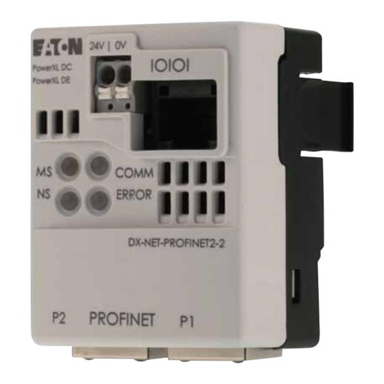
Page 20: Leds
2 Configuration 2.2 LEDs 2.2 LEDs The LEDs on the DX-NET-PROFINET2-2 communication interface are used to indicate operating and network statuses and to allow rapid diagnosis of prob- lems. ⑪ ⑫ ① ② ⑦ ③ ④ ⑧ ⑤ ⑥ ⑨... - Page 21 Reversible errors can be resolved by a reset or by power cycling the supply voltage (turning it off and then back on). In contrast, fatal errors can only be reset by power cycling the supply voltage or by changing the hardware configuration while the supply voltage is off. DX-NET-PROFINET2-2 01/22 MN040062EN www.eaton.com...
- Page 22 Communication is actively taking place with the basic unit. ERROR The ERROR LED indicates the internal communication status with the basic unit. LED status Description Off (red) No communication with the basic unit On (red) Communication error with the basic unit DX-NET-PROFINET2-2 01/22 MN040062EN www.eaton.com...
- Page 23 2 Configuration 2.2 LEDs DX-NET-PROFINET2-2 01/22 MN040062EN www.eaton.com...
-
Page 24: Installation
Observe the following information when setting up the system. DANGER All handling and installation work relating to the mechanical surface mounting and installation of the DX-NET-PROFINET2-2 communication interface may only be carried out in a voltage- free state. ... -
Page 25: Assembly
3 Installation 3.4 Assembly 3.4 Assembly The connection from the DX-NET-PROFINET2-2 communication interface to the PROFINET field bus is established via an RJ45 plug (see also → section 1.4.1, “PROFINET connection”, page 9). The DX-NET-PROFINET2-2 communication interface is connected to the front of the DC1 variable frequency drive or DE1 variable speed starter. - Page 26 3 Installation 3.4 Assembly → The DX-NET-PROFINET2-2 communication interface can be mounted on all DC1 variable frequency drives with degree of protection IP20 as well as on all DE1 variable speed starters. The DX-NET-PROFINET2-2 communication interface cannot, however, be used for DC1 variable frequency drives with degree of protection IP66.
-
Page 27: Installing The Field Bus
fieldbus cable ② and the mains and motor cable ①, in order to prevent electromagnetic interference on the fieldbus. Figure 14: Separate routing in the cable duct a Mains and motor connection cable b PROFINET cable → In all cases only use approved PROFINET cables. DX-NET-PROFINET2-2 01/22 MN040062EN www.eaton.com... -
Page 28: Commissioning
4.1 GSDML file The properties of a PROFINET card are described in a GSDML file. This is required in order to integrate the DX-NET-PROFINET2-2 communica- tion interface into a PROFINET network. → You will find a suitable GSDML file on the Internet at: Eaton.eu →... -
Page 29: Addressing
4 Commissioning 4.2 Addressing 4.2 Addressing The DX-NET-PROFINET2-2 communication interface is addressed with a MAC and IP address. Each device has a globally unique MAC address (6-byte Ethernet address): The first three bytes specify the ID, while the other three bytes specify the device's serial number, which is consecutive. - Page 30 Figure 16: Select the network adapter The program then displays all available communication interfaces. Figure 17: View of the available communication interfaces ▶ Select the DX-NET-PROFINET2-2 interface and set the desired address on the right. DX-NET-PROFINET2-2 01/22 MN040062EN www.eaton.com...
- Page 31 ▶ Click on Apply. Figure 18: Setting the IP address You will then see the assigned IP address under IP. Figure 19: The DX-NET-PROFINET2-2 communication interface now has an IP address assigned. Addressing is now complete. DX-NET-PROFINET2-2 01/22 MN040062EN www.eaton.com...
-
Page 32: Parameter Settings
Dual mode – Control and reference via PROFIdrive telegram – Enable via control signal terminal 1 Note: The PNU 928 parameter does not exist in the display of the basic devices (keypad or drivesConnect). Parameter PNU 928 can be accessed under the acyclic services. DX-NET-PROFINET2-2 01/22 MN040062EN www.eaton.com... -
Page 33: Configuration Of The Control Signal Terminals
Used to select between setpoint values Select DIG REF/AI2 REF Used to select between the digital speed reference value (set with the keypad or with the UP and DOWN commands) and analog setpoint value AI2 REF DX-NET-PROFINET2-2 01/22 MN040062EN www.eaton.com... - Page 34 No function No function EXTFLT No function f-Fix1/Select BUS REF Select Fire Mode/Normal OP Pre-set speed 4/2 f-Fix4/Select BUS REF Select Fire Mode/Normal OP No function Keypad REF/Select BUS REF Select Fire Mode/Normal OP No function DX-NET-PROFINET2-2 01/22 MN040062EN www.eaton.com...
-
Page 35: Operation
For PROFINET operation, a high signal must always be present at DI1. Figure 20: Enable signal for bus mode in DC1 variable frequency drives For PROFINET operation, a high signal must always be present at DI1. DX-NET-PROFINET2-2 01/22 MN040062EN www.eaton.com... -
Page 36: Specific Settings For Bus Operation
Changing the parameter values via drivesConnect or the control unit requires a connection to the RJ45 socket. This is located on the front of the communication interface. RJ45 RJ45 DX-CBL-PC-3M0 Figure 22: Parameterization via drivesConnect DX-NET-PROFINET2-2 01/22 MN040062EN www.eaton.com... - Page 37 “Access to acyclic process data”, page 102. Parallel communication via PROFINET, keypad, DX-COM-STICK3 or a PC cable connection is always possible. A real-time processing mode via drivesConnect is not, however, recommen- ded, as this would overload the processor. DX-NET-PROFINET2-2 01/22 MN040062EN www.eaton.com...
-
Page 38: Programming
PROFIdrive profile. Vendor specific 999 = “Transparent Mode” This is an Eaton-specific profile (manufacturer-specific telegram). The internal communication is converted to PROFINET IO data. Control and status data are processed as per the profile defined by the manufacturer (Eaton) DX-NET-PROFINET2-2 01/22 MN040062EN www.eaton.com... - Page 39 Dots are used to indicate priority levels. The more dots a transition has, the higher its priority. Status of the variable frequency drive/variable speed starter Command at the variable frequency drive/ Variable speed starter Figure 24: Displays in the status diagrams DX-NET-PROFINET2-2 01/22 MN040062EN www.eaton.com...
- Page 40 Bit 3 = 0 Bit 0 = 1 Bit 0 = 0 Bit 2 = 0 (EN_Op) (EN_Op) (OnOff) (OnOff) (Off3) S4: Operation Bit 0, 1, 2 = 1; Bit 6 = 0 Figure 25: Network status diagram: PROFIdrive DX-NET-PROFINET2-2 01/22 MN040062EN www.eaton.com...
- Page 41 Bit 3 = 0 Bit 0 = 1 Bit 0 = 0 Bit 2 = 0 (EN_Op) (EN_Op) (OnOff) (OnOff) (Off3) S4: Operation Bit 0, 1, 2 = 1; Bit 6 = 0 Figure 26: Network status diagram: PROFIdrive DX-NET-PROFINET2-2 01/22 MN040062EN www.eaton.com...
-
Page 42: Cyclic Data
Output data are data that come from the device, i.e. from the variable frequency drive (are “read out”) and enter the control/ PLC. Specifically actual values and status values. The same applies to input bytes or output bytes. “Output…”: variable frequency drive/variable speed starter -> PLC DX-NET-PROFINET2-2 01/22 MN040062EN www.eaton.com... -
Page 43: Input And Output Data Of The Cyclic Profiles
(VFD control) (FU frequency setpoint value) Vendor specific 999 Transparent Mode Control word 1 Control word 2 Control Word 3 Control word 4 4 x 16 bits (VFD control) (FU frequency (reserved) (ramp time) setpoint value) DX-NET-PROFINET2-2 01/22 MN040062EN www.eaton.com... -
Page 44: Output Data
Status word 1 Status word 2 Status word 3 Status word 4 4 x 16 bits (VFD status and (VFD frequency (motor current) (motor torque) actual errors) actual value) The individual parts of the words are explained below. DX-NET-PROFINET2-2 01/22 MN040062EN www.eaton.com... -
Page 45: Pdshort Profile
Vendor specific 1000 PDShort Control word 1 Control word 2 Control word 3 2 x 16-bit (VFD control) (VFD frequency (reserved) setpoint value) The individual parts of the words are explained below. DX-NET-PROFINET2-2 01/22 MN040062EN www.eaton.com... - Page 46 "Error" status. The external fault can be reset just like any other fault (with Fault acknowledge (bit 7) or by switching the supply voltage off and back on). 0: no external fault 1: external fault DX-NET-PROFINET2-2 01/22 MN040062EN www.eaton.com...
- Page 47 3. -100 % ≙ C000 -> reverse at 50 Hz Data type N2 Setpoints are displayed as integer values. 100 % ≙ 4000 The direction of rotation is specified with a negative setpoint: Example: -100 % ≙ C000 DX-NET-PROFINET2-2 01/22 MN040062EN www.eaton.com...
-
Page 48: Status Words
0: Ref. frequency not reached 1: Ref. Frequency reached Remote Input 1 Status of digital input 3 0: No voltage at DI3 1: 24 V DC present at DI3 → Bits 8 to 15 are not used. DX-NET-PROFINET2-2 01/22 MN040062EN www.eaton.com... - Page 49 3. -100 % ≙ C000 -> reverse at 50 Hz Data type N2 Table 14: Status word 3 – PDShort profile Byte Designation Meaning 0, …, 7 Motor current Current motor current High Data type N2 0, …, 7 DX-NET-PROFINET2-2 01/22 MN040062EN www.eaton.com...
-
Page 50: Profidrive Profile
Input word (control) of PLC -> variable length frequency drive/variable speed starter Standard Telegram 1 “Profidrive” Control word 1 (FU Control word 2 (FU 2x16 bits control) frequency setpoint value) The individual parts of the words are explained below. DX-NET-PROFINET2-2 01/22 MN040062EN www.eaton.com... - Page 51 This bit can be used to reset a fault in the variable frequency drive/variable speed starter. The fault acknowledge function will only respond to a rising edge, i.e., to the value chan- ging from 0 to 1. DX-NET-PROFINET2-2 01/22 MN040062EN www.eaton.com...
- Page 52 1 → 0 of the enable signal with the difference that the vari- able frequency drive goes into the Error status. The external fault can be reset just like any other fault (with Fault acknowledge (bit 7) or by switching the supply voltage off and on). DX-NET-PROFINET2-2 01/22 MN040062EN www.eaton.com...
- Page 53 3. -100 % ≙ C000 -> reverse at 50 Hz Data type: N2 The setpoints are displayed as integer values. 100 % ≙ 4000 The direction of rotation is specified with a negative setpoint: Example: -100 % ≙ C000 DX-NET-PROFINET2-2 01/22 MN040062EN www.eaton.com...
-
Page 54: Status Words
Output word (status) of variable frequency length drive/variable speed starter -> PLC Standard Telegram 1 “Profidrive” 2x16 bits Status word 1 (VFD Status word 2 (VFD status) frequency actual value) The individual parts of the words are explained below. DX-NET-PROFINET2-2 01/22 MN040062EN www.eaton.com... - Page 55 With a value of 1, the variable frequency drive/variable speed starter is in switching on inhibited mode and cannot be started. WARN Warning present 0: no warning 1: Warning Indicates whether there is a variable frequency drive/variable speed starter warning. DX-NET-PROFINET2-2 01/22 MN040062EN www.eaton.com...
- Page 56 2. f-max (P-01 = 50 Hz) - > 16384 = 0x4000 = 100 % -> The drive moves to the value set with f-min. 3. -100 % ≙ C000 -> reverse at 50 Hz Data type N2 DX-NET-PROFINET2-2 01/22 MN040062EN www.eaton.com...
-
Page 57: Simplified Start With The Profidrive Profile
The ramp stop is canceled and the variable frequency drive/variable speed starter continues to run. Table 26: Fault scenario Value Description 16#047F A fault occurs during ongoing operation. 16#0507 The variable frequency drive/variable speed starter is reset. 16#047F The variable frequency drive/variable speed starter starts after troubleshooting. DX-NET-PROFINET2-2 01/22 MN040062EN www.eaton.com... -
Page 58: Overview Of "Simplified Start With Profile 2
Setpoints via input bytes 2 and 3 are displayed as integer values. 100 % ≙ 4000 The direction of rotation is specified with a negative setpoint: Example: -100 % ≙ C000 Actual values are returned in the same format via output bytes 2 and 3. DX-NET-PROFINET2-2 01/22 MN040062EN www.eaton.com... -
Page 59: Transparent Mode Profile
Control word 1 These bits are used to control the variable frequency drive/variable speed starter. The content can be adapted to your application and then sent as a control word to the variable frequency drive/variable speed starter. DX-NET-PROFINET2-2 01/22 MN040062EN www.eaton.com... - Page 60 In the application, the values will be scaled by a factor of 0.01, 8, …, i.e. 300 ≙ 3 s. 15 High In this case, parameter P-12 must be set to 4 (only for the DC1 variable frequency drive). DX-NET-PROFINET2-2 01/22 MN040062EN www.eaton.com...
-
Page 61: Status Words
Zero speed Speed control deactivated Speed control activated Hardware enable signal not present Hardware enable signal present If bit 0 is not active, check the mains voltage. If no mains voltage is present, the bit = 0. DX-NET-PROFINET2-2 01/22 MN040062EN www.eaton.com... - Page 62 Table 35: Status word 4 – Transparent Mode profile Byte Designation Meaning 0, …, 7 Motor torque Current motor torque The motor torque is specified with one decimal place. Example: 1000 ≙ 100.0% 8, …, 15 High DX-NET-PROFINET2-2 01/22 MN040062EN www.eaton.com...
-
Page 63: Acyclic Data
100 ms ≙ 4971 ≙ 136B 86400000 ms (= 1 day) ≙ 4294967295 ≙ FFFFFFFF Normalized value N2 N2 is a normalized 16-bit value for relative scaling. N2 falls within a range of -200% to +200%. DX-NET-PROFINET2-2 01/22 MN040062EN www.eaton.com... - Page 64 In this bit string, 16 variables of type BOOLEAN are represented in two octets. Code: 115 = 73 Table 39: Bit sequence V2 Octet Bit 8 Bit 7 Bit 6 Bit 5 Bit 4 Bit 3 Bit 2 Bit 1 DX-NET-PROFINET2-2 01/22 MN040062EN www.eaton.com...
- Page 65 0 ≦ i ≦ 4294967295 x T Standard data types Table 42: Standard data types Data type Coding Integer8 Integer16 Integer32 Insigned16 Unsigned32 OctetString → For more information on data types, refer to the document IEC 61158-5: 2003. DX-NET-PROFINET2-2 01/22 MN040062EN www.eaton.com...
-
Page 66: Parameter List
A minus sign ( – ) means that the parameter is not available on the device. → For more detailed information on the individual parameters, please refer to the manuals for the corresponding basic devices. DX-NET-PROFINET2-2 01/22 MN040062EN www.eaton.com... - Page 67 P-26 P-42 STOP f-SkipBand1 P-29 – STOP U-max Details in Hz P-28 – STOP f-Umax Details in Volt – – STOP t-Excitation-V/f Magnetizing time, V/f method – – STOP PWM lower Limit Minimum PWM pulse width DX-NET-PROFINET2-2 01/22 MN040062EN www.eaton.com...
- Page 68 Deceleration ramp 2 – – t-decMulti2 Deceleration ramp 3 – – t-decMulti3 Deceleration ramp 4 – – n-decMulti1 Ramp 2-1 speed limit – – n-decMulti2 Ramp 3-2 speed limit – – n-decMulti3 Ramp 4-3 speed limit DX-NET-PROFINET2-2 01/22 MN040062EN www.eaton.com...
- Page 69 STOP Mutual inductance Stator resistance (Rs) – – STOP Stator resistance Meas Stator inductance – – STOP Stator inductance Meas Rotor resistance – – STOP PM-MotorSignalIn Enable signal injection – – STOP PM-MotorSignalInLevel Signal injection level DX-NET-PROFINET2-2 01/22 MN040062EN www.eaton.com...
- Page 70 Analog output 2 format – – AO1 scale Scaling for analog output 1 – – AO1 Offset Offset for analog output 1 P-63 ✓ ✓ STOP UInt16 UsedStateMachine 0: Communication lost 10: PROFIdrive profile 11: 8-bit profile DX-NET-PROFINET2-2 01/22 MN040062EN www.eaton.com...
- Page 71 Disadvantage: Higher loss in the device P00-32 P00-14 STOP Actual switching Current switching frequency. frequency If the auto temperature management func- tion is enabled, this value may be lower than the value set. DX-NET-PROFINET2-2 01/22 MN040062EN www.eaton.com...
- Page 72 P-15 P-15 STOP DI Config Select The setting determines the configuration of the control signal terminals depending on the setting with 928.0. For more information, please refer to the manual for the basic device. DX-NET-PROFINET2-2 01/22 MN040062EN www.eaton.com...
- Page 73 STOP f-fixed selection B2 – – STOP t-acc Select B0 – – STOP t-acc Select B1 – – STOP t-dec Select B0 – – STOP t-dec Select B1 P-21 P-22 P-21 P-22 P-21 P-22 P-21 P-22 DX-NET-PROFINET2-2 01/22 MN040062EN www.eaton.com...
- Page 74 Motor current Current motor current, in amperes P00-31 – STOP Calculated excitation Magnetizing current (I current P00-31 – STOP Calculated I-rotor Rotor current (I – – STOP Motor torque Motor torque – – STOP Motor Power Rel DX-NET-PROFINET2-2 01/22 MN040062EN www.eaton.com...
- Page 75 Output process data for field bus operation For more information, please refer to the manual for the basic device. – – STOP NETSendPZD4 Output process data for field bus operation For more information, please refer to the manual for the basic device. DX-NET-PROFINET2-2 01/22 MN040062EN www.eaton.com...
- Page 76 1: Locked. Parameter values can be displayed, but cannot be changed. If a remote keypad is connected, parameters cannot be accessed by the remote keypad if they are locked – – WORD ParameterAdaptation Motor parameter adaptation enable 0: deactivated 1: activated DX-NET-PROFINET2-2 01/22 MN040062EN www.eaton.com...
- Page 77 If this function is disabled, the motor thermal history is reset to zero on every power up. DX-NET-PROFINET2-2 01/22 MN040062EN www.eaton.com...
- Page 78 L3 input voltage P00-06 – STOP DC-Link Voltage Ripple DC link voltage ripple 29952 P-53 P-40 STOP Action@Communication Reaction after a loss of communication. Loss The delay time after a loss of communication is set using 362.0. DX-NET-PROFINET2-2 01/22 MN040062EN www.eaton.com...
- Page 79 The sample interval is 500 ms. P00-16 P00-16 STOP Heatsink2 Log P00-16 P00-16 STOP Heatsink3 Log P00-16 P00-16 STOP Heatsink4 Log P00-16 P00-16 STOP Heatsink5 Log P00-16 P00-16 STOP Heatsink6 Log P00-16 P00-16 STOP Heatsink7 Log DX-NET-PROFINET2-2 01/22 MN040062EN www.eaton.com...
- Page 80 P00-19 – STOP AmbientTemp5 Log P00-19 – STOP AmbientTemp6 Log P00-19 – STOP AmbientTemp7 Log ✓ ✓ STOP WarningWord Shows the current device warning P-36 P-34 STOP PDP address Unique drive address in a communication network. DX-NET-PROFINET2-2 01/22 MN040062EN www.eaton.com...
- Page 81 ✓ STOP UInt16 PDP DO NumberOfDOs 1 Do not read-out ✓ ✓ STOP UInt16 PDP DO subclass ✓ P-37 STOP UInt16 Parameter set The default settings will be restored if this parameter is set to 1. DX-NET-PROFINET2-2 01/22 MN040062EN www.eaton.com...
- Page 82 – Max Torque Timeout Time at maximum torque after which a fault message will be sent 2204 P-34 – Brake chopper Brake chopper activation For more information, please refer to the manual for the basic device. DX-NET-PROFINET2-2 01/22 MN040062EN www.eaton.com...
- Page 83 – – MSC Kp Speed controller proportional gain 2401 – – MSC Ti Speed controller integral time 2402 – – MSC Kd Speed controller differential term 2408 P-62 2500 – – STOP UserProgramID PLC program ID DX-NET-PROFINET2-2 01/22 MN040062EN www.eaton.com...
- Page 84 2901 – – DroopMax Droop speed 2901 – – DroopFeedback Droop speed 3221 P-36 P-47 3222 P-36 P-35 RS485-0 Baudrate Modbus Baud rate 3224 – – RS485-0 ParityType Modbus RTU data format 3254 P-57 3255 P-58 DX-NET-PROFINET2-2 01/22 MN040062EN www.eaton.com...
- Page 85 Time between the moment communications are lost and the moment the device is swit- ched off as a result. 3302 P-50 – CAN0 Baudrate CANopen Baudrate For more information, please refer to the manual for the basic device. 4211 P-13 DX-NET-PROFINET2-2 01/22 MN040062EN www.eaton.com...
-
Page 86: Further Explanations
In the error state, no communication takes place between the basic device, interface or PLC. In the event of an error, the reaction is defined via PNU 840.29952. Figure 33: Communication loss L1 /L L2 /N 9 10 11 Figure 34: Fault scenario DX-NET-PROFINET2-2 01/22 MN040062EN www.eaton.com... - Page 87 The variable frequency drive/variable speed starter runs to the end or communication returns with valid commands. DX-NET-PROFINET2-2 01/22 MN040062EN www.eaton.com...
- Page 88 In the error-free state, communication takes place between the basic device, interface and PLC (→ figure 35). In the event of an error, the variable fre- quency drive/variable speed starter continues to run, regardless of which communication path is interrupted. DX-NET-PROFINET2-2 01/22 MN040062EN www.eaton.com...
- Page 89 The parameter channel is always addressed with index 47. Protocol The main task of the DX-NET-PROFINET2-2 communication interface is to map the protocol in such a way that the parameter channel can be operated completely transparently by PROFINET communication.
- Page 90 Address of the parameter that should be accessed 0000 - FFFF (i.e. 0 - 65535 8, 9 Subindex Subindex Address of the parameter's first field element or start of the text 0000 - FFFF (i.e. 0 - 65535 DX-NET-PROFINET2-2 01/22 MN040062EN www.eaton.com...
- Page 91 The length depends on the format and can be a maximum of 4 bytes. 00000000 - FFFFFFFF (i.e. 0 - 4294967295 In this case, the number of bytes is variable (13, 14, or 16) and will depend on the selected format DX-NET-PROFINET2-2 01/22 MN040062EN www.eaton.com...
- Page 92 Write response – without data and errors if the write request was under- stood by the variable frequency drive/variable speed starter. Write request - error. If an error has occurred, the write response will contain an error. DX-NET-PROFINET2-2 01/22 MN040062EN www.eaton.com...
- Page 93 Table 48: Byte designation Byte Designation Description Request Reference Request identification: Is mirrored Response-ID Response ID: 81 : Read job(-); 82 : Write job(-) DO-ID Drive-Object-ID: Is mirrored No. of Parameters Number of parameters: 01 DX-NET-PROFINET2-2 01/22 MN040062EN www.eaton.com...
- Page 94 – – No text array available Attempting to access a text array that – is not available reserved – – – Request cannot be carried out Access is temporarily not possible ✓ due to operating status DX-NET-PROFINET2-2 01/22 MN040062EN www.eaton.com...
- Page 95 The length of the current response – meter manager exceeds the parameter manager's parameter processing capacity. Multiple parameter access not Is not supported. ✓ permissible 24, …, reserved – – 65, …, manufacturer specific – – DX-NET-PROFINET2-2 01/22 MN040062EN www.eaton.com...
- Page 96 Value: Specifies the value of the parameter being accessed. The length depends on the format and can be a maximum of 4 bytes. 00000000 - FFFFFFFF (i.e. 0 - 4294967295 Content of PNU 0 to PNU 999 (without PNU 202) DX-NET-PROFINET2-2 01/22 MN040062EN www.eaton.com...
- Page 97 Number of values: 01 : Value 6, …, 25 Value Value: Specifies the value of the parameter being accessed The length depends on the format and can be a maximum of 20 bytes. Content of PNU 202 DX-NET-PROFINET2-2 01/22 MN040062EN www.eaton.com...
-
Page 98: Errors And Diagnostics
4 Commissioning 4.12 Acyclic data 4.12.5 Errors and diagnostics The variable frequency drive/variable speed starter provides diagnostic mes- sages for itself and for the DX-NET-PROFINET2-2 communication interface. Basically, a distinction must be drawn between: • basic diagnostics (PROFINET basic diagnostics), •... - Page 99 FaultAck = 1. Warnings (WARN) cannot be acknowledged, since they are simply messages without an ensuing response (the variable frequency drives/variable speed starters). Available diagnostic messages (PNU 860.0 warnings and PNU 944 to PNU 952 errors). DX-NET-PROFINET2-2 01/22 MN040062EN www.eaton.com...
-
Page 100: Error Numbers
A phase in the motor cable is not connected or has a discontinuity. Out-Ph DC1…E1 No valid Modbus telegram was received within the specified time. Sc-FO1 DC1…E1 No valid CANopen frame was received within the specified time. Sc-FO2 DX-NET-PROFINET2-2 01/22 MN040062EN www.eaton.com... - Page 101 4 Commissioning 4.12 Acyclic data DX-NET-PROFINET2-2 01/22 MN040062EN www.eaton.com...
-
Page 102: Application Example
5 Application example 5.1 General This chapter describes how communication is established between a Siemens PLC and the DX-NET-PROFINET2-2 via PROFINET. The main section of this chapter describes how to access the process and parameter data of the variable frequency drive. -
Page 103: System Overview
13 14 ⑤ Figure 37: Integration of DX-NET-PROFINET2-2 into a PROFINET network a PC with engineering tool b I/O controller c Switch d DC1 variable frequency drive and DE1 variable speed starter with DX-NET-PROFINET2-2 e Motor DX-NET-PROFINET2-2 01/22 MN040062EN www.eaton.com... -
Page 104: Cyclic And Acyclic Communication With Tia Portal
Follow the instructions described in → section 4.2, “Addressing”. Peripheral addresses The peripheral address ranges for the data to be exchanged between a Siemens controller and the DX-NET-PROFINET2-2 device are defined in the configuration. The following section looks at these hardware addresses. If you change them, you will need to adjust the program accordingly. -
Page 105: Access To Cyclic Process Data
In this example, function block FB 286 is used to read or change the parame- ters. → The corresponding index numbers can be found in → section 4.12.3, “Parameter list”, page 63. The parameter table contains specific data for each parameter. DX-NET-PROFINET2-2 01/22 MN040062EN www.eaton.com... -
Page 106: Example Program - Dx-Net-Profinet2-2 With Tia Portal
5 Application example 5.7 Example program – DX-NET-PROFINET2-2 with TIA Portal 5.7 Example program – DX-NET-PROFINET2-2 with TIA Portal The following chapter explains how to configure a program in the TIA Portal. The hardware and software requirements are listed in detail. Basic program- ming and configuration steps are not described in this section. -
Page 107: Setting Up The Configuration In The Tia Portal
5 Application example 5.7 Example program – DX-NET-PROFINET2-2 with TIA Portal 5.7.3 Setting up the configuration in the TIA Portal The steps below describe how to create a project for cyclic and acyclic communication. Hardware configuration ▶1. Start the TIA Portal and create a new project. - Page 108 5 Application example 5.7 Example program – DX-NET-PROFINET2-2 with TIA Portal ▶3. Find a suitable CPU. Figure 40: Integrating a CPU ▶4. Locate a device description file (GSDML file) for the DX-NET- PROFINET2-2 device. Figure 41: Managing device description files (GSD)
- Page 109 ▶5. Install the device description file (GSDML file) Figure 42: Installing the GSDML file ▶6. Drag and drop the DX-NET-PROFINET2-2 into the network. Catalog -> Other PROFINET IO field devices -> Drives EATON Industries -> DX-NET-PROFINET2-2 Figure 43: Integrating the DX-NET-PROFINET2-2 device into the network ▶7.
- Page 110 5 Application example 5.7 Example program – DX-NET-PROFINET2-2 with TIA Portal Figure 44: Entering the IP address for the CPU Now for the DX-NET-ETHERNET2-2 device: ▶ Open Properties. ▶ Select Ethernet addresses. ▶ Insert a new subnet. ▶ Enter the desired IP address and subnet mask in the IP protocol area.
- Page 111 Figure 46: Connecting the ports ▶9. Assign a device name to the DX-NET-PROFINET2-2 communication interface. The following procedure is used to assign names in this example. The Assign device name option scans devices that are available online and then assigns names.
- Page 112 5 Application example 5.7 Example program – DX-NET-PROFINET2-2 with TIA Portal ▶10.Select the properties of the DX-NET-PROFINET2-2 communication interface. You can assign the IP address and the device name in the “PROFINET inter- face” settings. Then click Assign name. Figure 48: Assigning device names DX-NET-PROFINET2-2 01/22 MN040062EN www.eaton.com...
- Page 113 5 Application example 5.7 Example program – DX-NET-PROFINET2-2 with TIA Portal ▶11.Select the required telegram from the hardware catalog. In this example, “Standard Telegram 1” is used. Figure 49: Selecting a telegram Hardware and I/O address overview The assignment of inputs and outputs for programming is highlighted below.
-
Page 114: Software Configuration - Program For Cyclic And Acyclic Communication
5 Application example 5.7 Example program – DX-NET-PROFINET2-2 with TIA Portal 5.7.4 Software configuration – program for cyclic and acyclic communication 5.7.4.1 Acyclic communication With the help of the Siemens SINA_SPEED block, the variable frequency drive can be controlled cyclically with the “Standard Telegram 1”. - Page 115 5 Application example 5.7 Example program – DX-NET-PROFINET2-2 with TIA Portal Input and output parameters of the SINA_SPEED function block The following tables list the input and output parameters of the SINA_SPEED function block. Input parameters of the SINA_SPEED function block...
- Page 116 5 Application example 5.7 Example program – DX-NET-PROFINET2-2 with TIA Portal Output parameters of the SINA_SPEED function block The HWIDSTW and HWIDZSW block inputs must reference the hardware ID of “Standard Telegram 1”. Telegram slots Figure 52: Definition of the slots...
- Page 117 5 Application example 5.7 Example program – DX-NET-PROFINET2-2 with TIA Portal Specific information about the data block The inputs of “Standard Telegram 1” can be accessed via the InstSinaSpeed data block. The InstSinaSpeed data block contains the following information: •...
- Page 118 5 Application example 5.7 Example program – DX-NET-PROFINET2-2 with TIA Portal Configuration of the block ▶1. Open the SINA_SPEED block from the Drive_Lib library. Figure 54: Selecting the SINA_SPEED block from the Drive_Lib library ▶2. Insert the SINA_SPEED block into the “Program blocks” folder.
- Page 119 5 Application example 5.7 Example program – DX-NET-PROFINET2-2 with TIA Portal ▶3. Call the SINA_SPEED block in the Main OB (OB1). Assign a data block to the block. Figure 56: Call options ▶4. Declare inputs and outputs and call up addresses in OB1.
- Page 120 5 Application example 5.7 Example program – DX-NET-PROFINET2-2 with TIA Portal Figure 58: Network 1 Saving the project ▶5. Save the project and download it to the CPU. To do this, click Connect online. Figure 59: Connect online DX-NET-PROFINET2-2 01/22 MN040062EN www.eaton.com...
- Page 121 5 Application example 5.7 Example program – DX-NET-PROFINET2-2 with TIA Portal Control and monitoring In order to be able to control the variable frequency drive via the TIA Portal, the variables must be called in the monitoring table. Figure 60: Settings in the monitoring table The variable frequency drive can be started via the EnableAxis input.
- Page 122 5 Application example 5.7 Example program – DX-NET-PROFINET2-2 with TIA Portal 5.7.4.2 Acyclic communication For parameter access, an FB286 acyclic communication library must be added to OB1. The following describes how read and write blocks can be called. Block FB286 is assigned to SINA_PARA.
- Page 123 5 Application example 5.7 Example program – DX-NET-PROFINET2-2 with TIA Portal ▶2. Assign a name for the block. Figure 62: Assigning a name for the block ▶3. Drag and drop function block FB286 into the network. → The individual programming steps were skipped here.
- Page 124 5.7 Example program – DX-NET-PROFINET2-2 with TIA Portal The following figure shows the FB286 function block with variables. Figure 64: Function block FB286 The following figure shows the entry for the DX-NET-PROFINET2-2 commu- nication interface Figure 65: Entry for the DX-NET-PROFINET2-2 communication interface...
- Page 125 5 Application example 5.7 Example program – DX-NET-PROFINET2-2 with TIA Portal Loading a project ▶4. Select the appropriate controller in the project tree. Figure 66: Selecting the controller ▶5. Then load the project. DX-NET-PROFINET2-2 01/22 MN040062EN www.eaton.com...
- Page 126 5 Application example 5.7 Example program – DX-NET-PROFINET2-2 with TIA Portal 5.7.4.3 Reading/writing parameters in online mode Now you switch to online mode to record and write the parameter values. → You can find a description of the inputs and outputs of the block and how to fill in information about the data block in →...
- Page 127 5 Application example 5.7 Example program – DX-NET-PROFINET2-2 with TIA Portal Set the following data for the variables on the channels of function block FB286: ReadWrite = 0, read request ParaNo = 4, 4 parameters to be read Set the following values for the variables of the instance database of function...
- Page 128 5 Application example 5.7 Example program – DX-NET-PROFINET2-2 with TIA Portal Write To write parameters, set the following values for the variables in function block FB286. P1-02 (f-max) ReadWrite = 1, write request ParaNo = 4, 4 parameters to be written...
- Page 129 5 Application example 5.7 Example program – DX-NET-PROFINET2-2 with TIA Portal Changed parameter values The changed parameter values are shown below. Figure 69: Changed parameter values To change an individual parameter, the parameter value is written in the block in online mode.
- Page 130 5 Application example 5.7 Example program – DX-NET-PROFINET2-2 with TIA Portal 5.7.4.4 Input/output of the block Inputs Parameter Type Default Description setting Start BOOL Start of the job 0 = No job or cancel job 1 = Start and execute the job...
- Page 131 5 Application example 5.7 Example program – DX-NET-PROFINET2-2 with TIA Portal 5.7.4.5 General information about the data block Data structure of sxParameter: sxParameter[x].siParaNo := parameter number sxParameter[x1].siIndex := parameter index sxParameter[x].srValue := (value range ±1.175 495 x 10 to ±3.402823 x 10 ) –...
-
Page 132: Index
RJ45 jack ....... . . 9 DX-NET-PROFINET2-2 01/22 MN040062EN www.eaton.com... - Page 133 Eaton is dedicated to ensuring that reliable, efficient and safe power supply is available when it’s needed most. With unparalleled knowledge of electrical power management across industries, experts at Eaton deliver customized, integrated solutions to solve our customers’ most critical challenges.
Need help?
Do you have a question about the DX-NET-PROFINET2-2 and is the answer not in the manual?
Questions and answers