
Related Manuals for Eaton PROFIBUS-DP EZ204-DP


Summary of Contents for Eaton PROFIBUS-DP EZ204-DP
- Page 1 EZ204-DP PROFIBUS-DP Slave Interface User Manual May 2005 MN05013001E For more information visit: www.EatonElectrical.com...
-
Page 3: Dangerous Electrical Voltage
Warning! Dangerous electrical voltage! Before commencing the installation • Disconnect the power supply of the device. • Ensure that devices cannot be accidentally restarted. • Verify isolation from the supply. • Short circuit to earth. • Cover or enclose neighboring units that are live. - Page 4 • Emergency stop devices complying with IEC/EN 60204-1 must be effective in all operating modes of the automation devices.Unlatching the emergency-stop devices must not cause restart. • Devices that are designed for mounting in housings or control cabinets must only be operated and controlled after they have been installed with the housing closed.
-
Page 5: Table Of Contents
MN05013001E For more information visit: www.EatonElectrical.com Contents About This Manual... 7 Target readership... 7 Other manuals on the device... 7 Device designation... 8 Abbreviations ... 10 Writing conventions... 10 EZ204-DP ... 11 System overview... 12 Device setup ... 13 Device function description... 14 –... - Page 6 Contents For more information visit: www.EatonElectrical.com PROFIBUS-DP Functions... 31 Slave modules ... 31 Diagnostics data ... 32 GSD file ... 32 PROFIBUS certification ... 33 Inputs/Outputs, EZ700/800/EZD Operating Mode .. 35 “Inputs 3 bytes” module: operating mode, S1 – S8 ... 36 “Inputs 1 byte”...
- Page 7 MN05013001E For more information visit: www.EatonElectrical.com – Analog value comparator/threshold comparator: A1 – A16 ... 73 – Counter relays: C1 – C16 ... 76 – Operating hours counters: O1 – O4 ... 79 – Timing relays: T1 – T16 ... 81 –...
- Page 8 Contents For more information visit: www.EatonElectrical.com – Text output function blocks D01 ..D32 ... 142 – Data function blocks DB01 .. DB32 ... 145 – PID controllers DC01 .. DC32 ... 147 – Signal smoothing filters FT01 .. FT32 ... 150 –...
- Page 9 Glossary ... 193 Index ... 201 MN05013001E For more information visit: www.EatonElectrical.com...
-
Page 11: About This Manual
Target readership Other manuals on the device The following operating manuals should be followed: MN05013001E For more information visit: www.EatonElectrical.com About This Manual This manual has been produced for automation technicians and engineers. A thorough knowledge of the PROFIBUS-DP fieldbus and the programming of a PROFIBUS-DP master is required. -
Page 12: Device Designation
Device designation For more information visit: www.EatonElectrical.com This manual uses the following short names for equipment types, as far as the description applies to all of these types: • EZ512-..-..., EZ7..-..-... Type designation of the control relay, the point represents a placeholder for all characters used. -
Page 13: Device Designation
MN05013001E For more information visit: www.EatonElectrical.com • EZ-AB for – EZ512-AB... – EZ719-AB... • EZ-AC for – EZ512-AC-.. – EZ719-AC – EZ8..-AC-... • EZ-DC for – EZ512-DC-.. – EZ719-DC-.. – EZ8..-.DC-... • EZ-DA for – EZ512-DA... – EZ719-DA... Device designation... -
Page 14: Abbreviations
Abbreviations Writing conventions For more information visit: www.EatonElectrical.com This manual uses abbreviations with the following meanings: hex: Hexadecimal (number system with base 16) dec : Decimal (number system with base 10) bcd: binary coded decimal code Value Range Personal Computer Except for the first page of chapters and empty pages at the end, the top left of the page shows the chapter title and the top right of the page shows the current section for greater clarity. -
Page 15: Ez204-Dp
EZ204-DP The EZ204-DP communication module was developed for automation tasks using the PROFIBUS-DP fieldbus. The EZ204-DP is a gateway and can only be used in conjunction with the EZ700, EZ800 or EZD basic units. The EZ control relay or EZD device with a PROFIBUS-DP gateway always works as a slave station on the network. -
Page 16: System Overview
EZ204-DP System overview For more information visit: www.EatonElectrical.com The EZ204-DP slaves are integrated in a PROFIBUS-DP system. Figure 1: Integration of EZ204-DP in the DP network Master area, PLC or PC Slave area, e.g. EZ /EZD with DP interface MN05013001E... -
Page 17: Device Setup
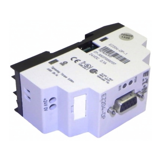
Device setup MN05013001E For more information visit: www.EatonElectrical.com P O W B U S Figure 2: View of the device PROFIBUS-DP connection, 9-pole SUB-D socket 24 V DC supply voltage Device designation plate BUS communication LED POW operation LED EZ-LINK socket Device setup... -
Page 18: Device Function Description
EZ204-DP Device function description For more information visit: www.EatonElectrical.com The EZ204-DP module allows the EZ and EZD series devices to be connected to a PROFIBUS-DP communication network. The following data can be transferred by selecting the appropriate SDO/PDO: EZ700/800, EZD-CP8.. •... -
Page 19: Ez800/Ezd-Cp8
Improper use MN05013001E For more information visit: www.EatonElectrical.com EZ800/EZD-CP8.. • All markers and EZ-NETdata • Function blocks (read/write, as viewed from the master) – Arithmetic function blocks – Frequency counters, high-speed counters, incremental encoder counters – 7-day and year time switch –... -
Page 21: Installation
Connecting EZ204-DP to the basic unit MN05013001E For more information visit: www.EatonElectrical.com Installation The same principles apply as for EZ700, EZ800 and EZD basic units with expansion devices. Figure 3: Fitting or removing basic unit the EZ204-DP to the... -
Page 22: Connecting The Power Supply
Installation Connecting the power supply For more information visit: www.EatonElectrical.com EZ7.. EZ8.. EZD-CP8.. Figure 4: Connection between basic unit and EZ204-DP The EZ204-DP unit is run on a 24 V DC power supply Section “Technical Data” from Page 187). Warning Always ensure electrical safety isolation between the extra low voltage (SELV) and the 24 V power supply. -
Page 23: Connecting Profibus-Dp
Connecting PROFIBUS-DP PROFIBUS-DP connection assignment MN05013001E For more information visit: www.EatonElectrical.com Connecting PROFIBUS-DP Use a 9-pole SUB-D plug to connect the PROFIBUS-DP interface to the PROFIBUS-DP fieldbus. For this use the special PROFIBUS-DP plug and the special PROFIBUS-DP cable available from the Eaton range of accessories. The type of cable used determines the permissible maximum bus length and the transfer rate. -
Page 24: Bus Terminating Resistors
Installation Bus terminating resistors EMC wiring For more information visit: www.EatonElectrical.com The first and last station in a bus segment must be connected to the bus with the bus terminating resistor switched on. The bus terminating resistor is switched externally. This external switch function can either be implemented as a separate bus terminating resistor or with a special Sub-D plug with an integrated bus termination. -
Page 25: Electrical Isolation
EZB4-102-KS1 Electrical isolation MN05013001E For more information visit: www.EatonElectrical.com EZB4-102-KS1 The following electrical isolation should be provided for the interfaces of the EZ204-DP: + – Figure 6: Potential isolation between the power supply and outputs Safe isolation of EZ-LINK 240 V AC Simple isolation of PROFIBUS-DP 24 V DC supply voltage Electrical isolation... -
Page 26: Transfer Rates - Automatic Baud Rate Detection
Installation Transfer rates – automatic baud rate detection Maximum distances/bus cable lengths For more information visit: www.EatonElectrical.com The EZ204-DP module automatically detects the baud rate used in the communication network after it is switched on. However, this requires that at least one station sends valid telegrams in the network. - Page 27 MN05013001E For more information visit: www.EatonElectrical.com Maximum distances/bus cable Distance between stations when using Type A cable to IEC 61158: Baud rate Max. cable length [Kbit/s] Type A cable 1200 19.2 1200 93.75 1200 187.5 1000 1500 3000 6000 12000 Distance between two stations when using Type B cable to IEC 61158: Baud rate...
-
Page 29: Device Operation
Initial power up MN05013001E For more information visit: www.EatonElectrical.com Device Operation Before you switch on the device, verify that it is properly connected to the power supply, to the bus connector and to the basic unit. Switch on the power supply to the basic unit and the PROFIBUS-DP expansion unit. -
Page 30: Setting The Profibus-Dp Station Address
Device Operation Setting the PROFIBUS-DP station address For more information visit: www.EatonElectrical.com Every PROFIBUS-DP station requires an unambiguous address in the PROFIBUS-DP structure. There are two ways of setting the PROFIBUS-DP addresses on the EZ204-DP: • Using the integrated display and keypad on the EZ or EZD basic unit •... - Page 31 MN05013001E For more information visit: www.EatonElectrical.com Setting the PROFIBUS-DP station Enter the System menu by pressing DEL + ALT simultaneously. PASSWORD... SYSTEM GB D F E I.. CONFIGURATOR Í Ú Use cursor buttons to select CONFIGURATOR PASSWORD... SYSTEM GB D F E I.. CONFIGURATOR Confirm your entry with OK With EZ800/EZD devices select the LINK...
-
Page 32: Setting The Address Using Ezsoft
Device Operation DP-DEVICE ADDRESS INPUT: 0002 204-05.30- D 2 . . . 9 0 1 . . . 1 0 9 . . . 2 . . . For more information visit: www.EatonElectrical.com EZ700 devices show the following dialog immediately: Set the address: Set the value of the current digit with buttons. -
Page 33: Status Leds
Status LEDs MN05013001E For more information visit: www.EatonElectrical.com The EZ204-DP expansion unit has two LEDs. POW LED, Function Figure 7: Function of the POW LED LED continuously lit: – Power supply present – Communication with the basic unit aborted LED flashing: –... -
Page 34: Cycle Time Of Ez Basic Unit
Device Operation Cycle time of EZ basic unit For more information visit: www.EatonElectrical.com Communication between the basic unit and EZ204-DP via EZ- LINK increases the cycle time of the basic unit. In extreme cases the cycle time may increase by 40 ms. This should be taken into account for the reaction times of the basic unit. -
Page 35: Profibus-Dp Functions
Slave modules Control level 1: Control commands, 9 – bytes Input/output level 2: Inputs, 3 bytes 3: Outputs, 3 bytes – 4: Inputs, 1 byte 5: Outputs, 1 byte – MN05013001E For more information visit: www.EatonElectrical.com PROFIBUS-DP Functions The EZ204-DP expansion module is a PROFIBUS-DP slave in compliance with IEC 61186/EN 50170. -
Page 36: Diagnostics Data
PROFIBUS-DP Functions Diagnostics data GSD file For more information visit: www.EatonElectrical.com The EZ204-DP device features the standard diagnostics in accordance with the PROFIBUS specification. Two additional diagnostics bytes are also sent. Byte 0 Length of additional diagnostics bytes Fixed 02 00000010 Byte 1 Status of EZ-LINK... -
Page 37: Profibus Certification
PROFIBUS certification MN05013001E For more information visit: www.EatonElectrical.com PROFIBUS certification EZ204-DP was certified as a PROFIBUS-DP device by the PROFIBUS User Organization. EZ204-DP contains the PROFIBUS VPC3+ interface. Irregular operation may occur under the following conditions: • When in a multimaster system Class I and Class II DP masters with parameter or configuration data access the slave at the same time (highly unlikely). -
Page 39: Inputs/Outputs, Ez700/800/Ezd Operating Mode
MN05013001E For more information visit: www.EatonElectrical.com Inputs/Outputs, EZ700/800/EZD Operating Mode The appropriate module must be selected in the slave configuration in order for I/O data to be transferred between the EZ204-DP slave and a PROFIBUS-DP master. The terms “input data” and “output data” are used from the point of view of the PROFIBUS-DP master. -
Page 40: Inputs 3 Bytes" Module: Operating Mode, S1 - S8
Inputs/Outputs, EZ700/800/EZD Operating Mode “Inputs 3 bytes” module: operating mode, S1 – S8 EZ/EZD operating mode with debounce without debounce For more information visit: www.EatonElectrical.com The normal PROFIBUS-DP master data exchange with the EZ204-DP slave is via input data bytes 0, 1, 2. Byte Meaning Scan the operating mode... - Page 41 “Inputs 3 bytes” module: operating mode, S1 – S8 Output MN05013001E For more information visit: www.EatonElectrical.com Table 2: Byte 1: Status of S1 to S8 on the basic unit Example: Value 19 S5, S4 and S1 are active. Attention! If control commands and I/O data are used at the same time: •...
-
Page 42: Inputs 1 Byte" Module: S1 - S8
Inputs/Outputs, EZ700/800/EZD Operating Mode “Inputs 1 byte” module: S1 – “Outputs 3 bytes” module: operating mode, R9 – R16, R1 – R8 For more information visit: www.EatonElectrical.com When this module is selected, the master only receives 1 byte (coil output data S1 to S8) via PROFIBUS. Byte Meaning Scan status of the EZ... - Page 43 “Outputs 3 bytes” module: operating mode, R9 EZ/EZD operating mode Index for setting the basic unit to the safety state Index for transferring valid data RUN command STOP command MN05013001E For more information visit: www.EatonElectrical.com Table 3: Byte 0: Operating mode 0 = status “0”, 1 = status “1”...
- Page 44 Inputs/Outputs, EZ700/800/EZD Operating Mode EZ/EZD Input For more information visit: www.EatonElectrical.com Table 4: Byte 1: Write status of R9 to R16 Example: Value 19 R13, R12 and R9 should be active. MN05013001E...
- Page 45 “Outputs 3 bytes” module: operating mode, R9 EZ/EZD Input MN05013001E For more information visit: www.EatonElectrical.com Table 5: Byte 2: Write status of R1 to R8 Example: Value 2B R6, R4, R2 and R1 should be active. Attention! If control commands and I/O data are used at the same time: •...
-
Page 46: Outputs 1 Byte" Module: R1 - R8
Inputs/Outputs, EZ700/800/EZD Operating Mode “Outputs 1 byte” module: R1 – R8 For more information visit: www.EatonElectrical.com When this module is selected, the master only sends 1 byte (coil output data S1 to S8) via PROFIBUS. Byte Meaning Status of R1 to R8 Requirement: The “Outputs;... -
Page 47: Control Commands For Ez700
Data exchange procedure MN05013001E For more information visit: www.EatonElectrical.com Control commands for EZ700 The “Control commands 9 bytes” module allows extended data exchange of the EZ700 on the PROFIBUS-DP communication bus. This allows you to transfer services from the following areas: •... - Page 48 Control commands for EZ700 Byte 0 Byte 1 For more information visit: www.EatonElectrical.com The master initiates the data exchange of the control commands and the addressed slave responds. During communication 9 data bytes (byte 0 = toggle byte, bytes 1 to 8 information bytes) are sent via PROFIBUS. The basic telegram structure is shown in the following diagram.
-
Page 49: Data Exchange Procedure
MN05013001E For more information visit: www.EatonElectrical.com Data exchange procedure In order to use input/output data and control commands simultaneously: Only after the “Control commands” data exchange has been completed, will the I/O data be refreshed. All specified commands and parameters must be transferred in hexadecimal format. - Page 50 Control commands for EZ700 Byte Contents Data 1 Data 2 Data 3 Data 4 Data 5 For more information visit: www.EatonElectrical.com Table 6: Index 0 – date and time of real-time clock Operand Hour 0 to 23 Minute 0 to 59 Day (1 to 28;...
- Page 51 MN05013001E For more information visit: www.EatonElectrical.com Data exchange procedure Table 8: Index 2 – Winter time (only valid if Area = “Rule” selected) Byte Contents Data 1 Area = Rule 5 – 8 Data 2 – 5 Winter time switching rule Switching rule bit array Please also read the detailed description in the EZ500/700 manual (MN05013003E).
- Page 52 Control commands for EZ700 For more information visit: www.EatonElectrical.com MN05013001E...
-
Page 53: Read/Write Image Data
Read/write image data MN05013001E For more information visit: www.EatonElectrical.com Read/write image data Please also observe the relevant description of possible image data provided in the EZ500/700 manual (MN05013003E) or in the EZSoft Help. The latest edition of the manual is available as a PDF file from the Internet at: www.EatonElectrical.com. -
Page 54: Overview
Control commands for EZ700 Operands Meaning A1 – A16 Analog value comparators/threshold comparators: A1 – A16 C1 – C16 Counters: C1 – C16 D1 – D16 Text function blocks: D1 – D16 I1 – I16 Local inputs: I1 – I16 IA1 –... -
Page 55: Analog Value Comparators/Threshold Comparators: A1 - A16
MN05013001E For more information visit: www.EatonElectrical.com Read/write image data Analog value comparators/threshold comparators: A1 – A16 The following commands are used to read the logic state of the individual analog value comparators A1 to A16. Telegram structure Byte Meaning Toggle byte Command: Read Response: Read successful... -
Page 56: Counters: C1 - C16
Control commands for EZ700 For more information visit: www.EatonElectrical.com Counters: C1 – C16 The following commands are used to read the logic state of the individual counters C1 – C16. Telegram structure Byte Meaning Toggle byte Command: Read Response: Read successful Command rejected Type... -
Page 57: Text Function Blocks: D1 - D16
MN05013001E For more information visit: www.EatonElectrical.com Read/write image data Text function blocks: D1 – D16 The following commands are used to read the logic state of the individual text function blocks (D markers). Telegram structure Byte Meaning Toggle byte Command: Read Response: Read successful Command... -
Page 58: Local Inputs: I1 - I16
Control commands for EZ700 For more information visit: www.EatonElectrical.com Local inputs: I1 – I16 This command string enables you to read the local inputs of the EZ700 basic unit. The relevant input word is stored in Intel format. Telegram structure Byte Meaning Toggle byte... - Page 59 MN05013001E For more information visit: www.EatonElectrical.com Read/write image data Table 13: Byte 5 to 6: Data 1 to 2 Data 1 Bit 7 Data 2 Bit 7...
-
Page 60: Local Analog Inputs: Ia1 - Ia4
Control commands for EZ700 For more information visit: www.EatonElectrical.com Local analog inputs: IA1 – IA4 The analog inputs on the EZ700 basic unit (I7, I8, I11, I12) can be read directly via PROFIBUS-DP. The 16-bit value is transferred in Intel format (Low Byte first). Telegram structure Byte Meaning... - Page 61 MN05013001E For more information visit: www.EatonElectrical.com Read/write image data Example: A voltage signal is present at analog input 1. The required telegrams for reading the analog value are as follows: Table 14: Example telegram for reading the value at the analog input Byte Meaning...
-
Page 62: Markers: M1 - M16/N1 - N16
Control commands for EZ700 For more information visit: www.EatonElectrical.com Markers: M1 – M16/N1 – N16 Telegram structure Byte Meaning Toggle byte Command: Write Response: Write successful Command rejected Type With M marker With N marker Index Data 1 (Low Byte) 6 –... - Page 63 MN05013001E For more information visit: www.EatonElectrical.com Read/write image data Example: Marker M13 is set. Byte Meaning Toggle byte Command: Write Response: Write successful Command rejected Type M marker Index Data 1 6 – 8 Data 2 – 4 1) Possible causes page 91 Value (hex), sent by Master...
-
Page 64: Markers: M1 - M16/N1 - N16
Control commands for EZ700 For more information visit: www.EatonElectrical.com Markers: M1 – M16/N1 – N16 Unlike the write operation, the marker read operation reads the entire marker area of a particular marker type (M or N) is read. Telegram structure Byte Meaning Toggle byte... - Page 65 MN05013001E For more information visit: www.EatonElectrical.com Read/write image data Table 15: Byte 5 to 6: Data 1 to 2 Data 1 Bit 7 Data 2 Bit 7 – Example: The N markers are read: Byte Meaning Toggle byte Command: Read Response: Read successful Command...
-
Page 66: Operating Hours Counters: O1 - O4
Control commands for EZ700 For more information visit: www.EatonElectrical.com Operating hours counters: O1 – O4 The following commands are used to read the logic state of the operating hours counters O1 – O4. Telegram structure Byte Meaning Toggle byte Command: Read Response: Read successful Command... -
Page 67: Local P Buttons: P1 - P4
MN05013001E For more information visit: www.EatonElectrical.com Read/write image data Local P buttons: P1 – P4 The local P buttons are the display cursor buttons of the EZ700 basic unit. You can scan the buttons in both RUN and STOP mode. Ensure that the P buttons are also activated via the System menu (in the basic unit). - Page 68 Control commands for EZ700 For more information visit: www.EatonElectrical.com Table 17: Byte 5: Data 1 Data 1 Bit 7 – – – – Example: Data 1 = 2 P3 is active. MN05013001E...
-
Page 69: Local Outputs: Q1 - Q8
MN05013001E For more information visit: www.EatonElectrical.com Read/write image data Local outputs: Q1 – Q8 The local outputs can be read directly via the PROFIBUS-DP fieldbus. Telegram structure Byte Meaning Toggle byte Command: Read Response: Read successful Command rejected Type Index Data 1 (Low Byte) 6 –... -
Page 70: Inputs/Outputs Of Ez-Link: R1 - R16/S1 - S8
Control commands for EZ700 For more information visit: www.EatonElectrical.com Inputs/outputs of EZ-LINK: R1 – R16/S1 – S8 This service allows you to read the local R and S data and the data of the NET stations (1 – 8) transferred via EZ-LINK, again from the relevant EZ700 image. - Page 71 MN05013001E For more information visit: www.EatonElectrical.com Read/write image data Table 19: Byte 5 to 6: Data 1 to 2 Data 1 Bit 7 Data 2 Bit 7 – – – –...
-
Page 72: Timing Relays: T1 - T16
Control commands for EZ700 For more information visit: www.EatonElectrical.com Timing relays: T1 – T16 The following commands are used to read the logic state of the individual timers T1 - T16. Telegram structure Byte Meaning Toggle byte Command: Read Response: Read successful Command rejected... -
Page 73: Year Time Switch: Y1 - Y8
MN05013001E For more information visit: www.EatonElectrical.com Read/write image data Year time switch: Y1 – Y8 The following commands are used to read the logic state of the individual year time switches. Telegram structure Byte Meaning Toggle byte Command: Read Response: Read successful Command rejected... -
Page 74: Master Reset: Z1 - Z3
Control commands for EZ700 For more information visit: www.EatonElectrical.com Master reset: Z1 – Z3 Telegram structure Byte Meaning Toggle byte Command: Read Response: Read successful Command rejected Type Index Data 1 (Low Byte) 6 – 8 Data 2 – 4 1) Possible causes page 91 Table 22:... -
Page 75: 7-Day Time Switch: Ö 1 - Ö 8
MN05013001E For more information visit: www.EatonElectrical.com Read/write image data ö ö 7-day time switch: 1 – The following commands are used to read the logic state of the individual 7-day time switches. Telegram structure Byte Meaning Toggle byte Command: Read Response: Read successful Command... -
Page 76: Read/Write Function Block Data
Control commands for EZ700 Read/write function block data Operands Meaning A1 – A16 Analog value comparator/threshold comparator: A1 – A16 C1 – C16 Counter relays: C1 – C16 O1 – O4 Operating hours counters: O1 – O4 T1 – T16 Timing relays: T1 –... -
Page 77: Analog Value Comparator/Threshold Comparator
MN05013001E For more information visit: www.EatonElectrical.com Read/write function block data Analog value comparator/threshold comparator: A1 – A16 Telegram structure Byte Meaning Toggle byte Command: Read Write Response: Read successful Write successful Command rejected Type Instance Index 5 – 8 Data 1 – 4 1) Possible causes page 91 2) EZ provides 16 analog comparators A1 to A16 for use as... - Page 78 Control commands for EZ700 Index (hex) 1) The value can only be written if it is assigned to a constant in the 2) A 16-bit value is transferred in data bytes Data 1 – Data 2. It should be For more information visit: www.EatonElectrical.com Table 24: Operand overview Operand...
- Page 79 Meaning Bit 15 14 13 12 11 10 9 Appears in the parameter menu Yes/no Compare FB not used EQ (=) GE ( ) LE ( ) GT (>) LT (<) Use as constant and therefore can be written to I1= Constant F1= Constant I2= Constant...
-
Page 80: Counter Relays: C1 - C16
Control commands for EZ700 Byte 5 – 8 1) Possible causes 2) EZ provides 16 counters C1 to C16 for use as required. These can be For more information visit: www.EatonElectrical.com Counter relays: C1 – C16 Telegram structure Meaning Toggle byte Command: Read Write... - Page 81 Index (hex) 1) The value can only be written if it is assigned to a constant in the program. 2) A 16-bit value is transferred in data bytes Data 1 – Data 2. It should be remembered that Data 1 is the low byte and Data 2 the high byte. Meaning Appears in the parameter menu Yes/no...
- Page 82 Control commands for EZ700 For more information visit: www.EatonElectrical.com Table 29: Index 01 – Control byte Data 1 FB output – – 1) Switch contact 2) Count direction: 0 = up counting, 1 = down counting 3) Reset, the timing relay is reset (reset coil) 4) Count coil, counts on every rising edge Example: the actual value of C3 is to be read:...
-
Page 83: Operating Hours Counters: O1 - O4
Byte 5 – 8 1) Possible causes 2) EZ provides 4 operating hours counters O1 to O4. These can be addressed using the instance (0 – 3). Index (hex) 1) The value can only be written if it is assigned to a constant in the program. - Page 84 Control commands for EZ700 Meaning Appears in the parameter menu Yes/no Use in the program Setpoint S1 Unused bits For more information visit: www.EatonElectrical.com Table 31: Index 00 – Parameters Bit 7 – – Example: Data 1 (Byte 5) = 0x01 Meaning: The values appear in the Parameter menu.
-
Page 85: Timing Relays: T1 - T16
Byte 5 – 8 1) Possible causes 2) EZ provides 16 timing relays T1 to T16 for use as required. These can MN05013001E For more information visit: www.EatonElectrical.com Read/write function block data Timing relays: T1 – T16 Telegram structure Meaning Toggle byte Command: Read... - Page 86 Control commands for EZ700 Index (hex) 1) The value can only be written if it is assigned to a constant in the 2) A 16-bit value is transferred in data bytes Data 1 – Data 2. It should be For more information visit: www.EatonElectrical.com Table 33: Operand overview Operand...
- Page 87 Meaning Appears in the parameter menu Yes/no Timer mode On-delayed Off-delayed On-delayed with random setpoint Off-delayed with random setpoint On and off delayed (two time setpoints) On and off delayed each with random setpoint (two time setpoints) Impulse transmitter Flashing relay (two time setpoints) Time base FB not used Millisecond: S...
- Page 88 Control commands for EZ700 For more information visit: www.EatonElectrical.com Table 35: Index 01 – Control byte Bit 7 6 5 4 3 FB input/output Data 3 – – – – ST 1) Switch contact 2) Enable, the timing relay is started (trigger coil) 3) Reset, the timing relay is reset (reset coil) 4) Stop, the timing relay is stopped (Stop coil) Example:...
-
Page 89: Year Time Switch: Y1 - Y8
MN05013001E For more information visit: www.EatonElectrical.com Read/write function block data Year time switch: Y1 – Y8 Telegram structure Byte Meaning Toggle byte Command: Read Write Response: Read successful Write successful Command rejected Type Instance Index 5 – 8 Data 1 – 4 1) Possible causes page 91 2) EZ provides 8 year time switches Y1 to Y8 for use as required. - Page 90 Control commands for EZ700 For more information visit: www.EatonElectrical.com Table 36: Operand overview Index Operand (hex) Parameters Table 37 Control byte Table 38 Channel A Time point ON Time point OFF Channel B Time point ON Time point OFF Channel C Time point ON Time point OFF Channel D...
- Page 91 MN05013001E For more information visit: www.EatonElectrical.com Read/write function block data Table 38: Index 01 – Control byte Data 1 Bit 7 FB output – – 1) Status 1, if the count condition is fulfilled. Channel A, Index 11/12 Index 0x11 channel A ON time Index 0x12 channel A OFF time Data 1 (Byte 5) –...
-
Page 92: Ö Ö
Control commands for EZ700 Byte 5 – 8 1) Possible causes 2) EZ provides 8 7-day time switches For more information visit: www.EatonElectrical.com Ö Ö 7-day time switch: 1 – Telegram structure Meaning Value (hex), sent by Master Toggle byte Command: Read Write... - Page 93 MN05013001E For more information visit: www.EatonElectrical.com Read/write function block data Table 39: Operand overview Index Operand (hex) Parameters Table 40 Control byte Table 41 Channel A Day on/off On time Off time Channel B Day on/off On time Off time Channel C Day on/off On time Off time...
- Page 94 Control commands for EZ700 For more information visit: www.EatonElectrical.com Table 40: Index 00 – Parameters Meaning Bit 7 Appears in the parameter menu Channel A Channel B Channel C Channel D Unused bits – – Example: Data 1 (Byte 5) = 0x03 Meaning: The values of the WH..
-
Page 95: Analysis - Error Codes Via Ez-Link
Analysis – error codes via EZ-LINK MN05013001E For more information visit: www.EatonElectrical.com Analysis – error codes via EZ-LINK The EZ700 basic unit will return a defined error code in the event of an incorrectly selected operating mode or an invalid telegram. - Page 96 Control commands for EZ700 For more information visit: www.EatonElectrical.com Table 42: Error codes Error Description code 0x01 Unknown telegram transmitted. 0x02 Unknown object transmitted. 0x03 Unknown command transmitted. 0x04 Invalid instance transmitted. 0x05 Invalid parameter set transmitted. 0x06 An attempt was made to write to a variable that is not a constant.
-
Page 97: Ez800/Ezd Control Commands
Data exchange procedure MN05013001E For more information visit: www.EatonElectrical.com EZ800/EZD Control Commands The Control commands 9 bytes module allows extended data exchange of the EZ800 and the EZD on the PROFIBUS-DP communication bus. This allows you to transfer services from the following areas: •... - Page 98 EZ800/EZD Control Commands Byte 0 Byte 1 For more information visit: www.EatonElectrical.com Byte 2 Byte 3 Byte 4 Byte 5 Byte 0 – Toggle byte Byte 0 is used to activate the sending of a control command with the toggle function. /861 fixed Procedure...
-
Page 99: Read/Write Date And Time
Read/write date and time MN05013001E For more information visit: www.EatonElectrical.com Read/write date and time Please also note the relevant description of the real-time clock provided in the EZ800 manual and the EZD manual. The latest edition of these manuals are available as PDF files from the Internet at: www.EatonElectrical.com. -
Page 100: Winter/Summer Time, Dst
EZ800/EZD Control Commands For more information visit: www.EatonElectrical.com Table 43: Byte 4 – 8: Data 1 – 5 Byte Contents Data 1 Hour (0 to 23) Data 2 Minute (0 to 59) Data 3 Day (1 to 28; 29, 30, 31; depending on month and year) Data 4... - Page 101 MN05013001E For more information visit: www.EatonElectrical.com Read/write date and time Table 44: Byte 4 – 8: Data 1 – 5 Byte Contents Data 1 Area None Manual Automatic EU Automatic GB Automatic US Data 21 Set summer time day (1 to 28, 29, 30, 31 depending on month and year) Data 31 Set Summer time month...
- Page 102 EZ800/EZD Control Commands For more information visit: www.EatonElectrical.com Example The real-time clock of the EZ800 is to be set to Friday 23.05.2003, 14:36. Byte Meaning Toggle byte Command: Write Response: Write successful Index Data 1 Data 2 Data 3 Data 4 Data 5 All values must be transferred as hexadecimal values.
-
Page 103: Read/Write Image Data
Read/write image data Operands Meaning Read local inputs IW0 IW1 – IW8 Read inputs of the stations IW1 to IW8 IA1 – IA4 Read local analog inputs IA1 to IA4 ID1 – ID16 Read local diagnostics ID1 to ID16 QW0, Read and write local QW0 outputs/outputs QW1 –... -
Page 104: Read Local Inputs Iw0
EZ800/EZD Control Commands For more information visit: www.EatonElectrical.com Read local inputs IW0 This command string enables you to read the local inputs of the EZ800/EZD. The relevant input word is stored in Intel format. Telegram structure Byte Meaning Toggle byte Command: Read Response: Read successful... - Page 105 MN05013001E For more information visit: www.EatonElectrical.com Read/write image data Example: Read local inputs IW0 Byte Meaning Toggle byte Command: Read Response: Read successful Type Index Data 1 Data 2 Data 3 Data 4 All values must be transferred as hexadecimal values. The values Data 1 = C4 and Data 2 = 02 indicate that the inputs I8, I7, I3 and I10 have been set to 1.
-
Page 106: Read Inputs Of The Stations Iw1 To Iw8
EZ800/EZD Control Commands For more information visit: www.EatonElectrical.com Read inputs of the stations IW1 to IW8 The EZ800 and EZD devices can be remotely expanded very simply using the EZ-NET. The service offered here makes it possible to implement read access to the inputs of individual NET stations. -
Page 107: Read Local Analog Inputs Ia1 To Ia4
MN05013001E For more information visit: www.EatonElectrical.com Read/write image data Read local analog inputs IA1 to IA4 The analog inputs on the EZ800 and EZD basic units can be read directly via PROFIBUS-DP. The 16-bit value is transferred in Intel format (LowByte first). Telegram structure Byte Meaning... - Page 108 EZ800/EZD Control Commands For more information visit: www.EatonElectrical.com Example A voltage signal is present at analog input 1. The required telegrams for reading the analog value are as follows: Byte Meaning Toggle byte Command: Read Response: Read successful Type Index Data 1 Data 2 Data 3...
-
Page 109: Read Local Diagnostics Id1 To Id16
MN05013001E For more information visit: www.EatonElectrical.com Read/write image data Read local diagnostics ID1 to ID16 The local diagnostics (ID1 – ID8) bytes indicate the status of the individual NET stations. The connection to the remote station (only EZD) is indicated via ID9. Telegram structure Byte Meaning... - Page 110 EZ800/EZD Control Commands For more information visit: www.EatonElectrical.com Table 46: Byte 5 to 6: Data 1 to 2 Data 1 Bit 7 Data 2 Bit 7 – – 0/1= active/inactive NET station, –= not assigned Example Data 1 = F8, Data 2 = FF In the EZ-NET network, the three stations are present with the NET IDs 1, 2, 3 MN05013001E...
-
Page 111: Read And Write Local Qw0 Outputs/Outputs Of The Stations Qw1 To Qw8
MN05013001E For more information visit: www.EatonElectrical.com Read/write image data Read and write local QW0 outputs/outputs of the stations QW1 to QW8 You can read and write the local outputs directly via PROFIBUS-DP. However, the outputs are only switched externally if the device is in Run mode and the addressed output is not being used in the circuit diagram. - Page 112 EZ800/EZD Control Commands For more information visit: www.EatonElectrical.com Table 47: Byte5: Data Data 1 Bit 7 MN05013001E...
-
Page 113: Reading And Writing Local Analog Output Qa1
MN05013001E For more information visit: www.EatonElectrical.com Read/write image data Reading and writing local analog output QA1 The commands provided can be used to access the local analog output of the EZ800 or EZD basic unit. When writing to the analog output, however, the value will only be output externally if the device concerned is in Run mode and the image concerned has not been overwritten by actual program. -
Page 114: Reading Local P Buttons
EZ800/EZD Control Commands For more information visit: www.EatonElectrical.com Reading local P buttons The local P buttons are the display cursor buttons of the EZ800/EZD basic unit. You can scan the buttons in both Run and Stop mode. Ensure that the P buttons are also activated via the SYSTEM menu (in the basic unit). - Page 115 MN05013001E For more information visit: www.EatonElectrical.com Read/write image data Table 48: Byte 5: Data Data 1 Bit 7 – – – –...
-
Page 116: Reading Rw.. Inputs/Sw.. Outputs From Ez-Link
EZ800/EZD Control Commands For more information visit: www.EatonElectrical.com Reading RW.. inputs/SW.. outputs from EZ-LINK This service allows you to read the local R and S data and the data of the NET stations (1 – 8) transferred via EZ-LINK, again from the relevant EZ800/EZD image. - Page 117 MN05013001E For more information visit: www.EatonElectrical.com Read/write image data Table 49: Byte 5 to 6: Data 1 to 2 Data 1 Bit 7 Data 2 Bit 7 – – – – – – – –...
-
Page 118: Reading Rw
EZ800/EZD Control Commands For more information visit: www.EatonElectrical.com Reading receive data network RN1 .. RN32/send data network SN1 .. SN32 EZ-NET allows a point-to-point connection to be implemented between the individual NET stations. The RN and SN data are used for the data exchange (see the EZ800 manual and EZD manual). - Page 119 MN05013001E For more information visit: www.EatonElectrical.com Read/write image data Table 50: Byte 5 to 8: Data 1 to 4 Data 1 Bit 7 Data 2 Bit 7 RN16 SN16 Data 3 Bit 7 RN17 SN17 RN24 SN24 Data 4 Bit 7 RN25 SN25 RN32 SN32...
-
Page 120: Reading And Writing Markers
EZ800/EZD Control Commands Byte 5 – 8 Operand Marker bit Marker byte Marker word Marker double word For more information visit: www.EatonElectrical.com Reading and writing markers Meaning Value (hex), sent by Master Toggle byte Command Read Write Response Read successful –... - Page 121 Applies to Left = Most MD, MW, significant bit, byte, MB, M word 32 bit 16 bit 8 bit 1 bit M32 to M25 32 bit 16 bit 8 bit 1 bit M64 to M57 MN05013001E For more information visit: www.EatonElectrical.com Read/write image data The latest editions of these manuals are available as PDF files from the Internet at:...
- Page 122 EZ800/EZD Control Commands For more information visit: www.EatonElectrical.com Example 1 Read marker bit M62 Byte Meaning Toggle byte Command: Read Response: Read successful Type Index Data 1 Data 2 Data 3 Data 4 Result: Data 1 = 01 M62 was set Value (hex), sent by Master Slave...
- Page 123 MN05013001E For more information visit: www.EatonElectrical.com Read/write image data Example 2 Write marker word MW32 with 823 = 337 Data 1 = 37 Byte Meaning Toggle byte Command: Write Response: Write successful Type Index Data 1 Data 2 Data 3 Data 4 , Data 2 = 03 Value (hex), sent by...
-
Page 124: Read/Write Function Block Data
EZ800/EZD Control Commands Read/write function block data For more information visit: www.EatonElectrical.com Please also note the relevant description of the function blocks provided in the EZ800 manual and the EZD manual. The latest edition of these manuals are available as PDF files from the Internet at: www.EatonElectrical.com manual search term: MN05013004E. -
Page 125: Overview
Operands Meaning A01 – A32 “Analog value comparators A01 .. A32” AR01 – AR32 “Arithmetic function blocks AR01 .. AR32” BC01 – BC32 “Block compare function blocks BC01 .. BC32” BT01 – BT32 “Block transfer function blocks BT01 .. BT32” BV01 –... -
Page 126: Analog Value Comparators A01 .. A32
EZ800/EZD Control Commands Byte 5 – 8 For more information visit: www.EatonElectrical.com Analog value comparators A01 .. A32 Telegram structure Meaning Value (hex), sent by Master Toggle byte page 94 Command: Read Write Response: Read successful – Write successful – Command –... - Page 127 Index Operand (hex) Bit IO, Table 53 Mode, Table 54 Comparison value 1 Gain factor for I1 (I1 = F1 χ value) Comparison value 2 Gain factor for I2 (I2 = F2 χ value) Offset for value I1 Switching hysteresis for value I2 (the value of HY is for both positive and negative hysteresis.) 1) The value can only be written if it is assigned to a constant in the program.
-
Page 128: Arithmetic Function Blocks Ar01 .. Ar32
EZ800/EZD Control Commands Byte 5 – 8 For more information visit: www.EatonElectrical.com Arithmetic function blocks AR01 .. AR32 Telegram structure Meaning Value (hex), sent by Master Toggle byte page 94 Command: Read Write Response: Read successful – Write successful – Command –... - Page 129 MN05013001E For more information visit: www.EatonElectrical.com Read/write function block data Table 55: Operand overview Index Operand (hex) Bit IO, Table 56 Mode, Table 57 First operand Second operand Result 1) The value can only be written if it is assigned to a constant in the program.
-
Page 130: Block Compare Function Blocks Bc01 .. Bc32
EZ800/EZD Control Commands Byte 5 – 8 For more information visit: www.EatonElectrical.com Block compare function blocks BC01 .. BC32 Telegram structure Meaning Value (hex), sent by Master Toggle byte page 94 Command: Read Write Response: Read successful – Write successful –... - Page 131 Index (hex) 1) The value can only be written if it is assigned to a constant in the MN05013001E For more information visit: www.EatonElectrical.com Read/write function block data Table 58: Operand overview Operand Bit IO, Table 59 Mode, Table 60 Source range 1 Target range 2 Number of elements to...
-
Page 132: Block Transfer Function Blocks Bt01 .. Bt32
EZ800/EZD Control Commands Byte Meaning Toggle byte Command: Read Write Response: Read successful Write successful Command rejected Type Instance Index 5 – 8 Data 1 – 4 Read operation Write operation Index Operand (hex) Bit IO, Mode, Source range 1 Target range 2 Number of elements to compare: max. - Page 133 MN05013001E For more information visit: www.EatonElectrical.com Read/write function block data The data for index 2 and 3 is transferred as a 32-bit value in Intel format (Data 1 – Low Byte .. Data 2 - High Byte). Table 62: Index 0 – Bit IO Bit 7 6 5 4 3 FB input Data 1 –...
-
Page 134: Boolean Sequence Function Blocks Bv01 .. Bv32
EZ800/EZD Control Commands Byte 5 – 8 For more information visit: www.EatonElectrical.com Boolean sequence function blocks BV01 .. BV32 Telegram structure Meaning Value (hex), sent by Master Toggle byte page 94 Command: Read Write Response: Read successful – Write successful –... - Page 135 MN05013001E For more information visit: www.EatonElectrical.com Read/write function block data Table 64: Operand overview Index Operand (hex) Bit IO, Table 65 Mode, Table 66 First operand Second operand Operation result 1) The value can only be written if it is assigned to a constant in the program.
-
Page 136: Counters C01 .. C32
EZ800/EZD Control Commands Byte 5 – 8 For more information visit: www.EatonElectrical.com Counters C01 .. C32 Telegram structure Meaning Value (hex), sent by Master Toggle byte page 94 Command: Read Write Response: Read successful – Write successful – Command – rejected Type Instance... - Page 137 Index Operand (hex) Bit IO Mode/Parameter Upper setpoint Lower setpoint Preset actual value Actual value in Run mode 1) The value can only be written if it is assigned to a constant in the program. MN05013001E For more information visit: www.EatonElectrical.com Read/write function block data Table 67: Operand overview...
-
Page 138: Frequency Counters Cf01 .. Cf04
EZ800/EZD Control Commands Byte 5 – 8 For more information visit: www.EatonElectrical.com Frequency counters CF01 .. CF04 Telegram structure Meaning Value (hex), sent by Master Toggle byte page 94 Command: Read Write Response: Read successful – Write successful – Command –... - Page 139 MN05013001E For more information visit: www.EatonElectrical.com Read/write function block data Table 69: Operand overview Index Operand (hex) Bit IO, Table 70 Mode/Parameter Upper setpoint Lower setpoint Actual value in Run mode 1) The value can only be written if it is assigned to a constant in the program.
-
Page 140: High-Speed Counters Ch01 .. Ch04
EZ800/EZD Control Commands Byte 5 – 8 For more information visit: www.EatonElectrical.com High-speed counters CH01 .. CH04 Telegram structure Meaning Value (hex), sent by Master Toggle byte page 94 Command: Read Write Response: Read successful – Write successful – Command –... - Page 141 Index Operand (hex) Bit IO Mode/Parameter Upper setpoint Lower setpoint Preset actual value Actual value in Run mode QV 1) The value can only be written if it is assigned to a constant in the program. MN05013001E For more information visit: www.EatonElectrical.com Read/write function block data Table 71: Operand overview...
-
Page 142: Incremental Encoder Counters Ci01 .. Ci02
EZ800/EZD Control Commands Byte 5 – 8 For more information visit: www.EatonElectrical.com Incremental encoder counters CI01 .. CI02 Telegram structure Meaning Value (hex), sent by Master Toggle byte page 94 Command: Read Write Response: Read successful – Write successful – Command –... - Page 143 Index Operand (hex) Bit IO Mode/Parameter Upper setpoint Lower setpoint Preset actual value Actual value in Run mode QV 1) The value can only be written if it is assigned to a constant in the program. MN05013001E For more information visit: www.EatonElectrical.com Read/write function block data Table 73: Operand overview...
-
Page 144: Comparators Cp01 .. Cp32
EZ800/EZD Control Commands Byte 5 – 8 For more information visit: www.EatonElectrical.com Comparators CP01 .. CP32 Telegram structure Meaning Value (hex), sent by Master Toggle byte page 94 Command: Read Write Response: Read successful – Write successful – Command – rejected Type Instance... - Page 145 MN05013001E For more information visit: www.EatonElectrical.com Read/write function block data Table 75: Operand overview Index Operand (hex) Bit IO, Table 76 Mode/Parameter Comparison value Comparison value 1) The value can only be written if it is assigned to a constant in the program.
-
Page 146: Text Output Function Blocks D01 ..D32
EZ800/EZD Control Commands Byte 5 – 8 For more information visit: www.EatonElectrical.com Text output function blocks D01 ..D32 Telegram structure Meaning Value (hex), sent by Master Toggle byte page 94 Command: Read Write Response: Read successful – Write successful – Command –... - Page 147 MN05013001E For more information visit: www.EatonElectrical.com Read/write function block data Table 77: Operand overview Index Operand (hex) Bit IO, Table 78 Mode/Parameter Text line 1, column 1 - 4 Text line 1, column 5 - 8 Text line 1, column 9 - 12 Text line 1, column 13 - 16 Text line 2, column 1 - 4 Text line 2, column 5 - 8...
- Page 148 EZ800/EZD Control Commands For more information visit: www.EatonElectrical.com Index Operand (hex) Scaling maximum value 2 Scaling maximum value 3 Scaling maximum value 4 Control information line 1 Control information line 2 Control information line 3 Control information line 4 1) The value can only be written if it is assigned to a constant in the program.
-
Page 149: Data Function Blocks Db01 .. Db32
Byte 5 – 8 MN05013001E For more information visit: www.EatonElectrical.com Read/write function block data Data function blocks DB01 .. DB32 Telegram structure Meaning Value (hex), sent by Master Toggle byte page 94 Command: Read Write Response: Read successful – Write successful –... - Page 150 EZ800/EZD Control Commands For more information visit: www.EatonElectrical.com Table 79: Operand overview Index Operand (hex) Bit IO, Table 80 Mode/Parameter Input value: value that is transferred to the QV output when the FB is triggered. Output value 1) The value can only be written if it is assigned to a constant in the program.
-
Page 151: Pid Controllers Dc01 .. Dc32
Byte 5 – 8 MN05013001E For more information visit: www.EatonElectrical.com Read/write function block data PID controllers DC01 .. DC32 Telegram structure Meaning Value (hex), sent by Master Toggle byte page 94 Command: Read Write Response: Read successful – Write successful –... - Page 152 EZ800/EZD Control Commands Index Operand (hex) Bit IO, Table 82 Mode, Table 83 Setpoint: –32768 to +32767 Actual value: –32768 to +32767 Proportional gain [%], Value range: 0 to 65535 Reset time [0.1 s], Value range: 0 to 65535 Rate time [0.1 s], Value range: 0 to 65535 Scan time = Time between function block calls.
- Page 153 MN05013001E For more information visit: www.EatonElectrical.com Read/write function block data Table 82: Index 0 – Bit IO Bit 7 6 5 4 FB input Data 1 – – – SE FB output Data 3 – – – – 1) Transfer of manual manipulated variable on status 1 2) Activation of D component on status 1 3) Activation of I component on status 1 4) Activation of P component on status 1...
-
Page 154: Signal Smoothing Filters Ft01 .. Ft32
EZ800/EZD Control Commands Byte 5 – 8 For more information visit: www.EatonElectrical.com Signal smoothing filters FT01 .. FT32 Telegram structure Meaning Value (hex), sent by Master Toggle byte page 94 Command: Read Write Response: Read successful – Write successful – Command –... - Page 155 Index Operand (hex) Bit IO, Table 85 Mode/Parameter Input value, value range: –32768 to +32767 Recovery time [0.1 s], Value range: 0 to 65535 Proportional gain [%], Value range: 0 to 65535 Delayed output value, value range: –32768 to +32767 1) The value can only be written if it is assigned to a constant in the program.
-
Page 156: Receive Network Data Function Blocks Gt01 .. Gt32
EZ800/EZD Control Commands For more information visit: www.EatonElectrical.com Receive network data function blocks GT01 .. GT32 Telegram structure Byte Meaning Toggle byte Command: Read Response: Read successful Command rejected Type Instance Index 5 – 8 Data 1 – 4 Table 86: Operand overview Index Operand... - Page 157 MN05013001E For more information visit: www.EatonElectrical.com Read/write function block data Table 87: Index 0 – Bit IO Bit 7 6 5 4 3 FB output Data 3 – – – – – 1) Status 1 if a new value is present that is transferred from the NET network.
-
Page 158: 7-Day Time Switches Hw01 .. Hw32
EZ800/EZD Control Commands For more information visit: www.EatonElectrical.com 7-day time switches HW01 .. HW32 Telegram structure Byte Meaning Toggle byte Command: Read Response: Read successful Command rejected Type Instance Index 5 – 8 Data 1 – 4 Table 89: Operand overview Index Operand (hex) - Page 159 Date 2 Weekday Date 4 Weekday m5 to m0: Minute (0 to 59) h4 to h0: Hour (0 to 23) d5 to d0: Weekday (0 = Sunday to 6 = Saturday) MN05013001E For more information visit: www.EatonElectrical.com Read/write function block data Table 90: Index 0 –...
- Page 160 EZ800/EZD Control Commands Date 2 = 0B Weekday Switch-on time: Weekday = 01 .. Monday Hour = 0D .. 1300 hours Minute = 22 .. 34 minutes Date 4 = 25 Weekday Switch-off time: Weekday = 04 .. Thursday Hour = 15 ..
-
Page 161: Year Time Switches Hy01 .. Hy32
MN05013001E For more information visit: www.EatonElectrical.com Read/write function block data Year time switches HY01 .. HY32 Telegram structure Byte Meaning Toggle byte Command: Read Response: Read successful Command rejected Type Instance Index 5 – 8 Data 1 – 4 Table 92: Operand overview Index Operand... - Page 162 EZ800/EZD Control Commands Date 2 Year Date 4 OFF y6 Year d4 ... d0: Day (1 .. 31), m3 ... m0: Month (1 .. 12), y6 ... y0: Year (0: 2000 .. 99: 2099) Index 2 – 5, Parameter channels A – D Date 2 Year Switch-on time:...
- Page 163 Index 2 – 5, Parameter channels A – D Date 2 Date 4 OFF y6 Year Switch-off time: Day = 3 = 03 = 0000 0011b Month = 10 (October) = 0A Year = 2012 = 0C = 0000 1100b MN05013001E For more information visit: www.EatonElectrical.com Read/write function block data...
-
Page 164: Value Scaling Function Blocks Ls01 .. Ls32
EZ800/EZD Control Commands Byte 5 – 8 For more information visit: www.EatonElectrical.com Value scaling function blocks LS01 .. LS32 Telegram structure Meaning Value (hex), sent by Master Toggle byte page 94 Command: Read Write Response: Read successful – Write successful –... - Page 165 MN05013001E For more information visit: www.EatonElectrical.com Read/write function block data Table 95: Operand overview Index Operand (hex) Bit IO, Table 96 Mode/Parameter Input value, value range: 32 bit Interpolation point 1, X coordinate, value range: 32 bit Interpolation point 1, Y coordinate, value range: 32 bit Interpolation point 2,...
-
Page 166: Master Reset Function Blocks Mr01
EZ800/EZD Control Commands For more information visit: www.EatonElectrical.com Master reset function blocks MR01 .. MR32 Telegram structure Byte Meaning Toggle byte Command: Read Response: Read successful Command rejected Type Instance Index Bit IO Mode 5 – 8 Data 1 – 4 Value (hex), sent by Master Slave... - Page 167 MN05013001E For more information visit: www.EatonElectrical.com Read/write function block data Table 97: Index 0 – Bit IO Bit 7 6 5 4 3 2 1 0 FB input Data 1 FB output Data 3 1) Trigger coil. The appropriate Reset is executed if the coil is triggered (with a rising edge).
-
Page 168: Numerical Converters Nc01 .. Nc32
EZ800/EZD Control Commands Byte 5 – 8 For more information visit: www.EatonElectrical.com Numerical converters NC01 .. NC32 Telegram structure Meaning Value (hex), sent by Master Toggle byte page 94 Command: Read Write Response: Read successful – Write successful – Command –... - Page 169 MN05013001E For more information visit: www.EatonElectrical.com Read/write function block data Table 99: Operand overview Index Operand (hex) Bit IO, Table 100 Mode, Table 101 Input value: operand to be converted Output value: contains the conversion result 1) The value can only be written if it is assigned to a constant in the program.
-
Page 170: Operating Hours Counters Ot01 .. Ot04
EZ800/EZD Control Commands Byte 5 – 8 For more information visit: www.EatonElectrical.com Operating hours counters OT01 .. OT04 Telegram structure Meaning Value (hex), sent by Master Toggle byte page 94 Command: Read Write Response: Read successful – Write successful – Command –... - Page 171 MN05013001E For more information visit: www.EatonElectrical.com Read/write function block data Table 102: Operand overview Index Operand (hex) Bit IO, Table 103 Mode/Parameter Upper threshold value Actual value of operating hours counter 1) The value can only be written if it is assigned to a constant in the program.
-
Page 172: Send Network Data Function Blocks Pt01 .. Pt32
EZ800/EZD Control Commands For more information visit: www.EatonElectrical.com Send network data function blocks PT01 .. PT32 Telegram structure Byte Meaning Toggle byte Command: Read Response: Read successful Command rejected Type Instance Index 5 – 8 Data 1 – 4 Table 104: Operand overview Index Operand (hex) - Page 173 MN05013001E For more information visit: www.EatonElectrical.com Read/write function block data Table 105: Index 0 – Bit IO Bit 7 6 5 4 3 FB input Data 1 – – – – – FB output Data 3 – – – – – 1) Trigger coil.
-
Page 174: Pulse Width Modulation Function Blocks Pw01 .. Pw02
EZ800/EZD Control Commands Byte 5 – 8 For more information visit: www.EatonElectrical.com Pulse width modulation function blocks PW01 .. PW02 Telegram structure Meaning Value (hex), sent by Master Toggle byte page 94 Command: Read Write Response: Read successful – Write successful –... - Page 175 Index Operand (hex) Bit IO, Table 107 Mode/Parameter Manipulated variable, value range: 0 to 4095 (12 bit) Period duration [ms], Value range: 0 to 65535 Minimum on duration [ms], Value range: 0 to 65535 1) The value can only be written if it is assigned to a constant in the program. MN05013001E For more information visit: www.EatonElectrical.com Read/write function block data...
-
Page 176: Synchronize Clock Function Block Sc01
EZ800/EZD Control Commands For more information visit: www.EatonElectrical.com Synchronize clock function block SC01 Telegram structure Byte Meaning Toggle byte Command: Read Response: Read successful Command rejected Type Instance Index 5 – 8 Data 1 – 4 Table 108: Operand overview Index Operand (hex) -
Page 177: Set Cycle Time Function Block St01
Byte 5 – 8 MN05013001E For more information visit: www.EatonElectrical.com Read/write function block data Set cycle time function block ST01 Telegram structure Meaning Value (hex), sent by Master Toggle byte page 94 Command: Read Write Response: Read successful – Write successful –... - Page 178 EZ800/EZD Control Commands For more information visit: www.EatonElectrical.com Table 110: Operand overview Index Operand (hex) Bit IO, Table 111 Mode/Parameter Cycle time in ms, value range: 0 – 1000 1) The value can only be written if it is assigned to a constant in the program.
-
Page 179: Timing Relays T01 .. T32
Byte 5 – 8 MN05013001E For more information visit: www.EatonElectrical.com Read/write function block data Timing relays T01 .. T32 Telegram structure Meaning Value (hex), sent by Master Toggle byte page 94 Command: Read Write Response: Read successful – Write successful –... - Page 180 EZ800/EZD Control Commands For more information visit: www.EatonElectrical.com Table 112: Operand overview Index Operand (hex) Bit IO, Table 113 Mode/Parameters, Table 114 Setpoint 1: Time setpoint 1 Setpoint 2: Time setpoint 2 (with timing relay with 2 setpoints) Actual value: Time elapsed in Run mode 1) The value can only be written if it is assigned to a constant in...
- Page 181 MN05013001E For more information visit: www.EatonElectrical.com Read/write function block data Table 114: Index 1 - Mode/Parameters Mode Data 1 Operating mode On-delayed On-delayed with random setpoint Off-delayed Off-delayed with random setpoint On and off delayed (two time setpoints) On and off delayed each with random setpoint (two time setpoints) Impulse transmitter Flashing relay (two time setpoints)
-
Page 182: Value Limitation Function Blocks Vc01 .. Vc32
EZ800/EZD Control Commands Byte 5 – 8 For more information visit: www.EatonElectrical.com Value limitation function blocks VC01 .. VC32 Telegram structure Meaning Value (hex), sent by Master Toggle byte page 94 Command: Read Write Response: Read successful – Write successful –... - Page 183 MN05013001E For more information visit: www.EatonElectrical.com Read/write function block data Table 115: Operand overview Index Operand (hex) Bit IO, Table 116 Mode/Parameter Input value Upper limit value Lower limit value Output value: outputs the value present at input I1 within the set limits. 1) The value can only be written if it is assigned to a constant in the program.
-
Page 185: Appendix
What Happens If ...? Event POW LED not lit POW LED flashing BUS LED not lit BUS LED lit Slave not signalling Write command rejected Actual value is zero MN05013001E For more information visit: www.EatonElectrical.com Appendix Explanation No power supply Data transfer via EZ-LINK OK No PROFIBUS-DP data communication... -
Page 186: Overview Of Commands
Appendix Overview of commands For more information visit: www.EatonElectrical.com EZ700 The commands are sorted in ascending order: Command value hex Write T1 timing relay setpoint Write T2 timing relay setpoint Write T3 timing relay setpoint Write T4 timing relay setpoint Write T5 timing relay setpoint Write T6 timing relay setpoint Write T7 timing relay setpoint... - Page 187 MN05013001E For more information visit: www.EatonElectrical.com Overview of commands Command value hex Write time switch 3 channel B Write time switch 3 channel C Write time switch 3 channel D Write time switch 4 channel A Write time switch 4 channel B Write time switch 4 channel C Write time switch 4 channel D Write analog value comparator A1...
- Page 188 Appendix For more information visit: www.EatonElectrical.com Command value hex Read time switch 4 channel A Read time switch 4 channel B Read time switch 4 channel C Read time switch 4 channel D Read time Read status of analog and digital inputs Read status of P buttons and operator buttons Read status of timing relays, counter relays, time switches and analog value comparators...
-
Page 189: Ez800/Ezd
Date and time Read/write date and time Winter/summer time, DST Image data Read/write image data Local inputs: I1 – I16 Read inputs of the stations IW1 to IW8 Read local analog inputs IA1 to IA4 Read local diagnostics ID1 to ID16 Read and write local QW0 outputs/outputs of the stations QW1 to QW8 Reading and writing local analog output QA1... - Page 190 Appendix Function blocks Read/write function blocks Receive network data function blocks GT01 .. GT32 Analog value comparators A01 .. A32 Arithmetic function blocks AR01 .. AR32 Boolean sequence function blocks BV01 .. BV32 Counters C01 .. C32 Frequency counters CF01 .. CF04 High-speed counters CH01 ..
-
Page 191: Technical Data
Technical Data Ambient temperature Installed horizontally/vertically Condensation Storage/transport temperature Relative air humidity Air pressure (operation) Corrosion resistance MN05013001E For more information visit: www.EatonElectrical.com General Standards and regulations Dimensions (W × H × D) Weight Mounting Ambient temperatures Cold to IEC 60068-2-1 Heat to IEC 60068-2-2 IEC 60068-2-30 IEC 60068-2-42... -
Page 192: Ambient Mechanical Conditions
Appendix Pollution degree Degree of protection Oscillations Shocks Drop Free fall, packaged Electrostatic discharge Electromagnetic fields Radio interference suppression Burst High-energy pulses (surge) EZ...-DC... Line-conducted interference For more information visit: www.EatonElectrical.com Ambient mechanical conditions EN 50178 IEC 60529 VBG4 IEC 60068-2-6 IEC 60068-2-27 IEC 60068-2-31 IEC 60068-2-32... -
Page 193: Dielectric Strength
MN05013001E For more information visit: www.EatonElectrical.com Dielectric strength Measurement of the clearance and creepage distance Dielectric strength Tools and cable cross-sections Solid min. max. Flexible with ferrule min. max. Slot-head screwdriver, width Tightening torque max. Power supply Rated voltage Rated value Permissible range Residual ripple Input current at 24 V DC... -
Page 194: Profibus-Dp
Appendix Device connection Electrical isolation Function Interface Bus protocol Baud rates Bus terminating resistors Bus addresses Services Inputs module Outputs module Control commands module For more information visit: www.EatonElectrical.com PROFIBUS-DP SUB-D 9-pole, socket Bus to power supply (simple) Bus and power supply to EZ basic unit (safe isolation) PROFIBUS-DP slave RS 485 PROFIBUS-DP... -
Page 195: Dimensions
Dimensions 35.5 MN05013001E For more information visit: www.EatonElectrical.com Figure 9: Dimensions EZ204-DP (mm) Dimensions 47.5 56.5... - Page 197 Acknowledge Active metal component Address Addressing Analog Automation device Baud Baud rate Bidirectional Bus cycle time Bus line Bus system MN05013001E For more information visit: www.EatonElectrical.com Glossary This glossary refers to subjects relating to PROFIBUS-DP. Acknowledgement returned by the receiving station after having received a signal.
- Page 198 Glossary Bus terminating resistor Capacitive coupling Chassis ground Coding element Command-capable modules Common potential Configuring Digital Earthing strip Electrical equipment For more information visit: www.EatonElectrical.com Resistor at the beginning and end of a bus line for preventing disturbance caused by signal reflections and for adapting bus cables.
- Page 199 Equipotential bonding Field supply Fieldbus Galvanic coupling Ground Ground (verb) Ground connection Hexadecimal MN05013001E For more information visit: www.EatonElectrical.com Abbreviation for “Electromagnetic Compatibility”. The ability of electrical equipment to function trouble-free within a particular environment without a negative effect on the environment concerned.
- Page 200 Glossary Impedance Inactive metal parts Inductive coupling Lightning protection Low impedance connection Master Master-slave mode Mode Module bus Multimaster mode For more information visit: www.EatonElectrical.com Abbreviation for “Input/Output”. Apparent resistance that a component or circuit of several components has for an alternating current at a particular frequency.
- Page 201 NAMUR Overhead Parameter assignment Potential-free PROFIBUS-DP PROFIBUS-DP address PROFIBUS-DP master PROFIBUS-DP slave Protected against short-circuit Property of electrical equipment. Short-circuit-proof MN05013001E For more information visit: www.EatonElectrical.com Abbreviation for “Normen-Arbeitsgemeinschaft für Mess- und Regeltechnik” (Standards Work Group for Instruments and Controls). NAMUR proximity switches represent a special category of 2-wire proximity switches.
- Page 202 Glossary Protective conductor Radiated coupling Reference ground Reference potential Repeater Response time RS 485 Serial Shield Shielding Slave Station SUB-D plug For more information visit: www.EatonElectrical.com A conductor required for the protection against dangerous currents, designated by the letters PE (abbreviation of “Protective Earth”).
- Page 203 Topology UART Unidirectional MN05013001E For more information visit: www.EatonElectrical.com Geometric structure of a network or circuit arrangement. Abbreviation for “Universal Asynchronous Receiver/ Transmitter”. A UART is a logic circuit used for converting an asynchronous serial data sequence into a bit-parallel data sequence or vice versa.
- Page 205 MN05013001E For more information visit: www.EatonElectrical.com Index 7-day time switch EZ700 ... 71, 88 EZ800/EZD (read) ... 154 Address range ... 26 Analog comparators EZ700, read and write ... 73 EZ700, read status ... 51 Read/write (EZ800/EZD) ... 122 Analog inputs EZ700, read status ...
- Page 206 For more information visit: www.EatonElectrical.com Data exchange procedure EZ700 ... 43 EZ800/EZD ... 93 Data function block, read/write (EZ800/EZD) ... 145 Debounce ... 36 Diagnostics byte ... 32 Diagnostics, local EZ800/EZD (read) ... 105 Digital inputs EZ700, read status ... 54 EZ800/EZD, read status ...
- Page 207 MN05013001E For more information visit: www.EatonElectrical.com Inputs, network stations EZ800/EZD, read status ... 102 Invalid operating mode ... 91 Invalid telegram ... 91 Local inputs EZ700, read status ... 54 Local outputs EZ700, read status ... 65 Read/write (EZ800/EZD) ... 109 Local P buttons EZ800/EZD (read) ...
- Page 208 For more information visit: www.EatonElectrical.com POW LED ... 29 Power supply ... 18 PROFIBUS-DP connection assignment ... 19 Pulse width modulation Read/write (EZ800/EZD) ... 170 Reaction times (basic unit) ... 30 Read/write date EZ700 ... 45 EZ800/EZD ... 95 Read/write time EZ700 ...
- Page 209 MN05013001E For more information visit: www.EatonElectrical.com Text output function block Read/write (EZ800/EZD) ... 142 Threshold value comparator EZ700, read status ... 51 Threshold value switch EZ700 ... 73 Time change EZ800 ... 96 Timing relays EZ700 ... 81 EZ700, read status ... 68 Read/write (EZ800/EZD) ...
- Page 212 Eaton Electrical 1000 Cherrington Parkway Moon Township, PA 15108-4312 Tel: 1-800-525-2000 www.EatonElectrical.com © 2005 Eaton Corporation All Rights Reserved Printed in USA Publication No. MN05013001E May 2005...
Need help?
Do you have a question about the PROFIBUS-DP EZ204-DP and is the answer not in the manual?
Questions and answers