Table of Contents
Advertisement
Quick Links
ELC-GP04
Instruction Sheet
GRAPHIC PANEL SERIES
WARNING
•
DANGER - DC input power must be disconnected before any maintenance. Do not connect or
disconnect wires and connectors while power is applied to the circuit. Maintenance must be
performed by qualified technicians.
•
DANGER - The ELC-GP04 requires 24VDC input power. The 24VDC input power should not be
connected to the RS-485 communication port. The unit may be destroyed or can't be repaired if
the input power is improperly applied. Please always check the correctly input power wiring
before apply power.
•
DANGER - An electrical charge will remain on the DC-link capacitors for 1 minute after power
has been removed. Do not conduct any wiring or investigation on the ELC-GP04 until 1 minute
after power has been removed. Do NOT touch terminals when power on.
•
CAUTION - Always ground the ELC-GP04 by using the grounding terminal. Not only this acts as
a safety, but also filter out electrical noise. The ground method must comply with the laws of the
country where the unit is to be installed.
•
CAUTION - ELC-GP04 may be damaged if the fixed support (shipped with the pack) is adjusted
too tight.
•
Please carefully read this instruction before using the ELC-GP04.
•
The ELC-GP04 display panel is waterproof. But please prevent grease, corrosive liquids and
sharp objects from contacting the ELC-GP04.
•
Battery replacement: please use UL component type: CR2032 lithium battery (NOTE: RTC
should be reset after changing battery).
•
Do not disconnect while circuit is live unless area is known to be non-hazardous.
•
This equipment is suitable for use in Class I, Division 2, Groups A, B, C, D or Non-Hazardous
Locations only.
•
Explosion Hazard – Substitution of components may impair suitability for class I, Division 2.
•
Explosion Hazard – Do not disconnect equipment unless power has been switched off or the
area is known to be Non – Hazardous.
•
Power, input and output (I/O) wiring must all be in accordance with Class I, Division 2 wiring
methods, Article 501-4 (b) of the National Electrical Code, NEPA 70,or as specified in Section
18-152 of the Canadian Electrical Code for units installed within Canada, and in accordance
with that location's authority.
1
INTRODUCTION
1.1 Model Explanation
Thank you for choosing Eaton Logic Controller (ELC) GP Series. The features of ELC-GP04 are:
resolution is 128*64, display 8*4 Chinese characters (max.) and multi-language support. It is built-in
two communication ports (RS-232 and RS-485/RS-422, can be used simultaneously), and Built-in
RTC and communication/alarm indication LED.
Possess extension slot for ELC-GPXFERMOD to copy settings and programs rapidly and save
download time. Built-in variety objects to meet your requirement.
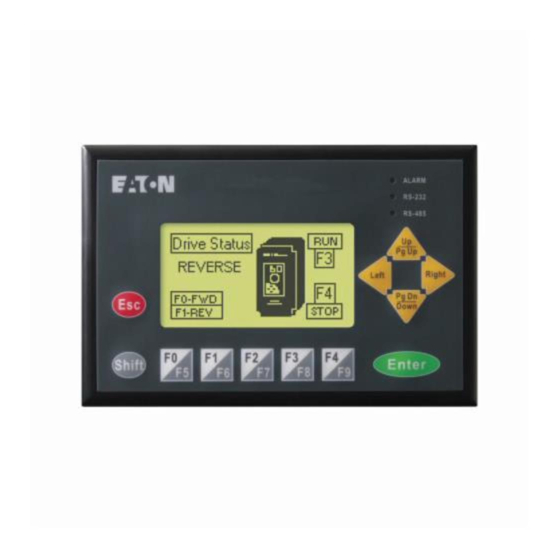
1.2 Outline
1.3 Panel Function Explanation
PANEL COMPONENT
EXPLANATION
Status 1: When power is on, the LED will flash three times slowly.
Alarm Indication LED
Status 2: When there is an abnormal situation, the LED will flash quickly along with an
(RED)
alarm sound.
RS-232 Indication LED
It will be flashing when transmitting program and communicating by using RS-232.
(Yellow)
RS-485/RS-422
It will be flashing when communicating by using RS-485/RS-422.
Indication LED (Green)
LCD Display Area
Liquid Crystal Module display area used to display current program state.
Escape/Exit
Used to cancel an incorrect input, or to Exit a programming step.
UP/Pg Up: Used to increase the value or move up one page.
Pg Dn/DOWN: Used to decrease the value or move down one page.
Arrow Keys
Left: Left direction key. (move curser to left)
Right: Right direction key. (move cursor to right)
Shift Key
Used to select keys F5, F6, F7, F8, F9.
Enter Key
Used to input a value or accept a programming command.
F0/F5: They are used to be constant 0 (F0) and 5 (Shift+F0) when they are in system
menu and user can define the functions separately when they are in user page.
F1/F6: They are used to be constant 1 (F1) and 6 (Shift+F1) when they are in system
menu and user can define the functions separately when they are in user page.
F2/F7: They are used to be constant 2 (F2) and 7 (Shift+F2) when they are in system
Function Keys
menu and user can define the functions separately when they are in user page.
F3/F8: They are used to be constant 3 (F3) and 8 (Shift+F3) when they are in system
menu and user can define the functions separately when they are in user page.
F4/F9: They are used to be constant 4 (F4) and 9 (Shift+F4) when they are in system
menu and user can define the functions separately when they are in user page.
1.4 Back Panel
BATTERY
SWITCH OR
RS-485/422
1.5 Dimension
Front panel (unit: mm [inch])
97.00
[3.82]
147.00 [5.79]
Vertical view (Unit: mm)
1.6 Installation
Mounting ELC-GP04 into the opening is done by carefully fitting the unit into the opening and
pressing firmly on all four corners. You could fix it by using the fixed support packaged with
ELC-GP04.
Warning: If you turn the screw exceeds torque: 4-5(kg-cm), ELC-GP04 may be damaged.
(Note:the flat surface should be a Type 4 "Indoor Use Only" enclosure or equivalent.)
Please leave sufficient space (more than 50mm) around the unit for heat dissipation.
Thickness:
0.5~9.0mm
50mm
2
2.1 Electrical Specification
ITEM
Function Key/Digital Key
External Input Power
Memory Capacity
CPU
RAM of System
Communication Interface
Waterproof Class of Front Panel
Environment Condition
Storage Temperature for Hardware
5-PIN terminals:
Wire gauge: 12-24 AWG
Vibration
Torque: 4.5 lb.-inch
Impact
Radiated Emission
Electrostatic Discharge Immunity
Radiated Immunity
Electrical Fast Transient
Right side diagram (unit: mm [inch])
Weight/Dimension
Cooling Method
Temperature Code
85.00
Hazardous Location rating
[3.35]
2.2 Function Specification
ITEM
Screen
Color
Backlight
Resolution
Display Range
Contrast Adjustment
IL05003006E.pdf
Mounting dimension (unit: mm [inch])
50mm
85
[3.35]
135~136.5[5.31~5.37]
Thickness Range 0.5~9mm
SPECIFICATION
ELC-GP04
F0~F4, ESC, SHIFT, ENTER and ARROW keys
24VDC (-15%~20%) 3.5W MAX.
256K Byte
Hitachi HD64F3064F
32K Byte
COM1: RS232; COM2: RS485/RS422(See Section 6)
IP65/NEMA4/UL Type 4 (indoor use)
0~50℃, relative humidity 20-90% RH (non-condensing)
-20~60℃
5Hz≦f<9Hz = Continuous: 1.75mm / Occasional: 3.5mm
9Hz≦f≦150Hz = Continuous: 0.5g / Occasional: 1.0g
15g peak, 11ms duration, half-sine, three shocks in each direction per
axis, on 3 mutually perpendicular axes (total of 18 shocks)
CISPR11, Class A
EN61000-4-2
EN61000-4-3
EN61000-4-4
0.24kg/147×97×35.5mm (Width × Height × Deep)
Natural Air Cooling
T6
Class I, Division 2, Group A, B, C, and D
ELC-GP04
STN-LCD
Monochromatic
The back-light automatic turn off time is 1~99 minutes
(0 = do not turn off)
(back-light life is about 50 thousand hours at 25℃)
128X64 Points
72mm (W) X 40mm (H); 3.00" (diagonal preferred)
10-step contrast adjustment
Advertisement
Table of Contents

Related Manuals for Eaton ELC-GP04


Summary of Contents for Eaton ELC-GP04
- Page 1 IL05003006E.pdf 1.3 Panel Function Explanation 1.6 Installation Mounting ELC-GP04 into the opening is done by carefully fitting the unit into the opening and PANEL COMPONENT EXPLANATION pressing firmly on all four corners. You could fix it by using the fixed support packaged with Status 1: When power is on, the LED will flash three times slowly.
- Page 2 GP XMOD XMOD GP RS-422: 4. Date and Time: It is used to set the ELC-GP04 built-in RTC including year, month, day, Turn the switch on the XMOD to XMOD GP Turn the switch on the XMOD to GP XMOD hour, minute, second and week.
Need help?
Do you have a question about the ELC-GP04 and is the answer not in the manual?
Questions and answers