Table of Contents
Advertisement
Quick Links
A-Series With Display
ACCESS MANAGEMENT SYSTEM
Models 3006-2xx, 3007-2xx, 3028-2xx, and 3029-2xx
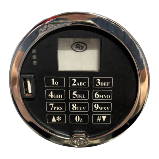
The Sargent & Greenleaf A-Series with Display
designed to provide a high level of security combined with flexible features that allow multiple levels of control over
normal operations and service access. Follow these instructions carefully to get the best possible use from your lock.
•
For instructions in English, visit the website: www.sargentandgreenleaf.com/ASeriesWithDisplay/
•
Für Anweisungen auf Deutsh besuchen Sie bitte die folgende website: www.sargentandgreenleaf.com/ASeriesWithDisplay/
•
Pour obtenir les instructions en français, veuillez consulter le site ci-dessous:
•
Para obtener instrucciones en español, visite la siguiente página web:
Introduction
•
It is recommended you run the latest version of Lock Management System (LMS). Running an older version of LMS
may not give you access to all features of lock firmware.
•
S&G electronic safe locks incorporate sophisticated electronic circuitry. These locks are suitable for indoor use
only.
•
The keypad should only be cleaned with a soft, dry cloth. Avoid using solvents or liquids.
•
Never attempt to lubricate the lock or keypad components. Service should only be performed by a qualified
technician.
•
Anytime the keypad is removed from its mounting base, either disconnect the lock cable or support the keypad
so that it does not hang by the cable. This could adversely affect the cable connector or the keypad receptacle.
•
Each time a button is pressed and the lock accepts the input, it will emit a beep, the red LED on the keypad will
flash momentarily, and a * will be displayed on the screen.
•
All the letters of the English alphabet are displayed on the keypad. This allows you to devise numeric,
alphanumeric, or word-based codes. Use whatever approach works best for you.
•
All codes end with #. This signals to the lock that you have finished entering all digits of the code.
•
Personal data directly related to a code holder, such as a birthdate, should not be used in making up a lock code.
Avoid codes that can be easily guessed.
•
After the lock is changed to a new code, check the lock function by locking and unlocking at least
3 times with the container door open. Make sure the lock functions correctly before closing the door.
•
The audit features, peripheral devices and accessories, software features, one-time code functionality, USB
functionality, and other additional features are beyond the scope of the UL 2058 standard and are not a part of the
UL Listing.
Sargent & Greenleaf, Inc.
One Security Drive
Nicholasville, KY 40356
Phone: (800)-826-7652 Fax: (800)-634-4843
Phone: (859)-885-9411 Fax: (859)-887-2057
Copyright 2005-2018 Sargent & Greenleaf, Inc.
Programming and
™
Operations Guide
TM
Locks (models 3006-2xx, 3007-2xx, 3028-2xx, and 3029-2xx) are
www.sargentandgreenleaf.com/ASeriesWithDisplay/
www.sargentandgreenleaf.com/ASeriesWithDisplay/
Sargent & Greenleaf S.A.
9, Chemin du Croset
1024 Ecublens, Switzerland
Phone: +41-21 694 34 00
Fax: + 41-21 694 34 09
Document 630-902
Revised 05/10/2019
Advertisement
Table of Contents

Subscribe to Our Youtube Channel
Related Manuals for Sargent and Greenleaf A-Series


Summary of Contents for Sargent and Greenleaf A-Series
- Page 1 Operations Guide Models 3006-2xx, 3007-2xx, 3028-2xx, and 3029-2xx The Sargent & Greenleaf A-Series with Display Locks (models 3006-2xx, 3007-2xx, 3028-2xx, and 3029-2xx) are designed to provide a high level of security combined with flexible features that allow multiple levels of control over normal operations and service access.
-
Page 2: Table Of Contents
TABLE OF CONTENTS 1. GENERAL INFORMATION .............................. 4 1.1 — About Your Locking System..........................4 1.2 — Factory Default Settings ............................. 4 2. OPERATING THE LOCK ..............................5 2.1 — Operating Mode, PIN Positions, and User Codes ....................5 2.2 —... - Page 3 3.16 — Command 43: Identify Lock Mechanics ......................20 3.17 — Command 44: Identify Operating Mode (Bank Mode) ..................20 3.18 — Command 45: Initializing the Lock ........................20 3.19 — Command 46: Setting Up the Time Delay Override Options................20 3.20 —...
-
Page 4: General Information
The S&G A-Series with Display Electronic Lock has the following hardware components: Lock – There are four different lock models available for the A-Series with Display Platform. These models include the 3006 (Pivot Bolt), 3007 (Direct Drive), 3028 (Motor Driven, Dead Latching), and 3029 (Motor Driven, Push / Pull). -
Page 5: Operating The Lock
2. OPERATING THE LOCK 2.1 — Operating Mode, PIN Positions, and User Codes The A-Series with Display Lock has a code hierarchy of Programmer (PIN position 00) Managers (PIN positions 01, 02, 03) Supervisors (PIN positions 0409) Users (PIN positions 10 through 29) See Tables A &... -
Page 6: Beep Patterns
Start time delay (when programmed). Send duress alarm (when programmed). Change their PIN Code. 2.3 — Beep Patterns The following table lists the beep patterns heard when using the A-Series with Display Lock. beep1 is the sound emitted when any single button is pressed... -
Page 7: Opening The Lock
2.4 — Opening the Lock Time Delay —The lock may be programmed with a time delay from 0 - 99 minutes with an opening window of 1 minute to 99 minutes. If your lock does not use the time delay: Enter: Your 8-digit PIN Code # Turn the safe handle to the unlocked position within 6 seconds. -
Page 8: Low Battery Indicator
2.9 — Low Battery Indicator If you enter a correct User Code and hear 5 double beeps when the lock opens, the batteries are low. Change the batteries. You will also see the following icon on the screen: If the batteries are so low that the lock can’t open, the lock will beep 20 times when a User code is entered. Change the batteries right away and re-enter a User code to open the lock. -
Page 9: Programming The Lock
3. PROGRAMMING THE LOCK These programming commands allow you to perform a variety of lock functions. Command ... . . Description/Function 0 0 *... . . Enable/disable manual secure 0 3*. -
Page 10: Command 00: Enable/Disable Manual Secure Mode
3.1 — Command 00: Enable/Disable Manual Secure Mode You can enable or disable the motor behavior in the 3006/3028/3029 locks. This will keep the lock motor in the retracted or unlocked position until you enter the 00# command, causing the lock motor/bolt to return to the secure position. This To enable/disable manual secure mode, perform the following steps: should be performed before initialization. -
Page 11: Command 04: Set Daylight Savings Time - Start Date
Example To set the start day to the last Sunday in March: Step 1 Enter: 0 4 * ♪♪♪♪♪ Step 2 Enter: 0 0 1 2 3 4 5 6 # ♪♪♪ Step 3 Enter: 0 4 0 1 0 3 # ♪♪♪... -
Page 12: Command 06: Verify Daylight Savings Mode Settings
3.6 — Command 10: Enable Daylight Savings Time In order to implement Daylight Savings Time (DST) features, you must enable the DST feature. Once the DST features have been enabled, the lock will automatically update the time to match the settings that were entered with the 03 –... -
Page 13: Command 12: Set Time
3.8 — Command 12: Set Time You must set the time to use Service Mode and audit trail functions. The time should be set in HHmm format based on a 24-hour clock, where HH = hours and mm = minutes. The time should be set before initializing the lock. The time is to always be set in local standard time. -
Page 14: Command 22: Changing A Pin Code
3.10 — Command 22: Changing a PIN Code Use command 22 to change your PIN Code. You should always leave the safe door open while changing codes. When changing any code, you will need to enter the new 8-digit PIN Code twice for confirmation. The PIN position does not change. -
Page 15: Command 28: Audit Download (Bank Mode)
3.11 — Command 28: Audit Download The A-Series with Display Lock Audit Trail can store as many as 1,000 events that include times & dates. Some examples of events are: • Adding or deleting a PIN code. • Changing a PIN code. -
Page 16: Command 32: Setting The Operating Mode
3.12 — Command 32: Setting the Operating Mode Enable Manager/Employee Mode The lock may be enabled for Manager/Employee mode by performing the following steps: Step 1 Enter: 3 2 * ♪♪♪♪♪ Step 2 Enter: 8-digit Programmer Code # ♪♪♪ Step 3 Enter: 2 (Function Number) # ♪♪♪... -
Page 17: Enable Day / Night Mode #1
Enable Day / Night Mode #1 For “Day / Night Mode #1”, the customer can setup the lock so that there is an opening window where the lock can be opened using one valid user. The opening window is established using command 59. Once in the opening window, the lock can be enabled for “day mode”... -
Page 18: Command 33: Changing A Pin Code
Try the new PIN Code at least three times to confirm operation before closing the safe door. 3.14 — Command 38: Setting the Duress Alarm Feature The A-Series with Display Lock has an optional duress, or silent alarm, option that can be configured. Using the Duress Alarm Feature To send a duress alarm to the alarm center, enter any code that is one number higher or lower than the last number of a normal PIN Code and press the # key. -
Page 19: Command 42: Identify Lock Type
Lock Type Step 1 Enter: 4 2 * A-Series Step 2 Listen for the beeps to determine the lock type. The lock will emit one low beep, one high beep, and one low beep to begin the sequence. The next set of beeps will indicate the type of lock being used. -
Page 20: Command 43: Identify Lock Mechanics
Please see Section 4.1 – Initializing the Lock for more information on initializing the lock. 3.19 — Command 46: Setting Up the Time Delay Override Options When the time delay feature is enabled, the A-Series with Display Lock can be programmed with a time delay override (TDO) feature that will allow a specific user to bypass the time delay countdown. -
Page 21: Command 47: Setting Up The Time Delay
3.20 — Command 47: Setting up the Time Delay The A-Series with Display Lock can be programmed with a time delay feature. Time delay applies only to those users who can open the lock. The time delay can be set from 0 to 99 minutes. If the lock is in the time delay period, the red LED light on the keypad flashes and a single beep sounds every 10 seconds. -
Page 22: Command 48: Setting Up The Opening Window
Do not set the time delay until you have finished all other programming functions, or you will have to wait through the time delay before making any other programming changes. Set time delay duration If the time delay has already been set, enter a User Code to start the time delay. When the time delay expires (the lock emits 10 rapid beeps) and the opening window has begun, immediately proceed to change the time delay by performing the following steps: Step 1... -
Page 23: Command 54: Initializing The Lock
Please see Section 4.1 – Initializing the Lock for more information on initializing the lock. 3.23 — Command 55: Enable / Disable the Lock (manager / employee mode) The A-Series with Display Lock can be programmed to work in Manager/Employee mode. In this mode, Managers and Supervisors enable the lock and Users open the lock (only when enabled). -
Page 24: Command 57: Enable/Disable Managers And Supervisors To Open The Lock In Manager / Employee Mode
3.25 — Command 57: Enable/Disable Managers and Supervisors to Open the Lock in Manager / Employee Mode When the lock is in Manager/Employee mode, the lock can be setup to allow the Managers and Supervisors to open the lock. By default, Managers and Supervisors can enable & disable the lock. Command 57 allows Managers and Supervisors to open the lock in Manager/Employee mode or disable this ability. -
Page 25: Command 75: Adding Code Positions (Manager / Employee/ Multi User / Dual)
3.27 — Command 75: Adding Code Positions (Manager/Employee - Multi User Mode) To add a user position, perform the following steps: Step 1 Enter: 7 5 * ♪♪♪♪♪ Step 2 Enter: 8-digit Manager PIN Code (01, 02, or 03) # ♪♪♪... -
Page 26: Command 77: Pin Position Verification
3.28 — Command 76: Deleting Code Positions To delete a user position, perform the following steps: Step 1 Enter: 7 6 * ♪♪♪♪♪ Step 2 Enter: 8-digit Manager PIN Code (01, 02, or 03) # ♪♪♪ Step 3 Enter: New 2-digit PIN position to delete # ♪♪♪... -
Page 27: Command 79: Identify Firmware Version
Example To set the time as 1:42 PM, use 13:42 (using the factory default Codes): Step 1 Enter: 7 8 * ♪♪♪♪♪ Step 2 Enter: 0 0 1 2 3 4 5 6 # ♪♪♪ Step 3 Enter: 1 3 4 2 # ♪♪♪... -
Page 28: Command 90: Display Lock Serial Number
3.34 — Command 90: Display Lock Serial Number This command will allow the user to view the lock serial number on the display. Step 1 Enter: 9 0 * Lock Serial 12345678 3.35 — Command 96: Check Battery Level This command will allow the user to check the estimated battery level. An icon will show the approximate battery level of the unit. -
Page 29: Service Mode Operation
To initialize multiple locks or initialize locks remotely (Command 45): Step 1 Set the date & time using the appropriate procedures. Step 2 Snap the Management touch key into the keypad extension receptacle. ♪♪♪♪♪ Step 3 4 5 * 0 1 2 3 4 5 6 # Step 4 The yellow LED will remain lit during the initialization process. -
Page 30: Service Mode Operation Codes
The yellow LED will be illuminated, the iButton icon will be displayed, and the green LED will flash in conjunction with a periodic beep. This beeping will prompt the User to present the touch key. The User will have approximately 15 seconds to present the touch key before the lock resets. -
Page 31: Program Bank Features
4.3.1.1 — Open Lock (Manual Secure) If the lock has been configured for manual secure, the user will need to enter 00# to return the lock motor to the secured position. The Display interface will show a “00#“ icon indicating to the user the lock has been configured for manual secure mode. -
Page 32: Download Audit Log With Manager Key
4.3.9 — Download Audit Log with Manager Key This is a management operation code that downloads the audit log of the lock. This code does not open the lock. The lock’s entire audit log (up to 400 events) is transferred to the touch key for uploading and reporting to the Lock Management System. -
Page 33: Pin Code Verification Worksheet (Bank Mode)
5. PIN Code Verification Worksheet (Bank Mode) Code Set? Position Description User Name/Initials YES or NO Programmer Manager Manager Manager Supervisor Supervisor Supervisor Supervisor Supervisor Supervisor User User User User User User User User User User User User User User User User User... -
Page 34: Appendix A - Beep Patterns / Display Icons
APPENDIX A – Beep Patterns / Display Icons Action / Description Beep Response Display Icon Key Press 1 beep ---------- Lock Processing -------------------- Penalty Time 2 BRAPs whenever key is pressed ---------- 3 quick beeps at start of time delay 1 beep every 10 seconds during time delay -------------------- Time Delay... - Page 35 Action / Description Beep Response Display Icon Set Time Enter Code --------------------------- Enter Time HH:MM 5 beeps after valid Programmer Code is entered Lock Programming – 78* Set Time 3 beeps after each valid programming entry --------------------------- (legacy command) 1 BRAP after incorrect entry Confirm Time HH:MM Start Clock...
- Page 36 Action / Description Beep Response Display Icon S: WW/DD/MM 5 beeps after valid Programmer Code is entered Lock Programming – 06* Verify --------------------------- 3 beeps after each valid programming entry DST Settings E: WW/DD/MM 1 BRAP after incorrect entry HHmm Enable DST Enter Code ---------------------------...
- Page 37 Action / Description Beep Response Display Icon Add Code Enter Auth Code --------------------------- Enter New Code 5 beeps after valid authorization code is entered Position 3 beeps after position is entered --------------------------- Lock Programming – 75* Add Code 3 beeps after new code is entered Enter New 3 beeps after new code is entered / 1 BRAP if failed Code...
- Page 38 Action / Description Beep Response Display Icon Audit Download Enter Code --------------------------- 5 beeps after valid Programmer code is entered # Events Lock Programming – 28* Audit Trail 3 beeps after selection (1-6) (Bank Mode) 3 beeps after selection / 1 BRAP if failed --------------------------- Confirm (1-6)
- Page 39 Action / Description Beep Response Display Icon Enable Service Enter Code --------------------------- 5 beeps after valid Programmer code is entered Lock Programming – 45* Initialize Yellow LED flashes --------------------------------- (while reading touch key) 1001 Enable Service Enter Code --------------------------- 5 beeps after valid Programmer code is entered Lock Programming –...
- Page 40 Yellow LED flashes (while reading touch key) Touch Key Security Bit Not Set ----------------------------- 1 BRAP Page:40...
-
Page 41: Appendix B - Error Codes
APPENDIX B – Error Codes Result/Error Code Description Type 1002 Operation timeout iButton 1003 Invalid touch key used iButton 1004 Touch key header issue iButton 1005 Touch key checksum error iButton 1006 Touch key “unsecure” iButton 1007 Owner block not found iButton 1008 Unrecognized iButton/wrong iButton type... -
Page 42: Appendix C - 1006/2006/3006 Pivotbolt Specifications
APPENDIX C – 1006/2006/3006 PivotBolt Specifications Attaching Screws: Use only the screws provided with the lock. They must engage the mounting plate by at least four full threads. Do not use lock washers or thread sealing compounds. Recommended Attaching Screw Torque: 30 to 40 inch-pounds (33.9 to 45.2 dNm) Minimum Lock Cable (Spindle) Hole Diameter: 0.312 inch (7.9 mm) Maximum Lock Cable (Spindle) Hole Diameter: 0.406 inch (10.3 mm) Lock is Designed to Move: 0.0 lbs. - Page 43 S&G Confidential The information contained in this document is proprietary to Sargent & Greenleaf, Inc. Any publication or duplication of this copyrighted document is strictly prohibited. WARRANTY A-Series with Display Electronic Safe Lock and Model 31KP Keypad Limited Warranty Seller warrants that for two (2) years from the date of shipment from Seller’s point of manufacture, the goods will be free from defects in material and workmanship, provided the goods are normally and properly used according to the Seller’s written instructions.
Need help?
Do you have a question about the A-Series and is the answer not in the manual?
Questions and answers