Advertisement
Quick Links
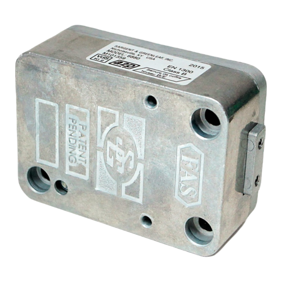
Installation and Operating Instructions for:
6860, 6870, 6880, 6890 Key Operated Safe Lock
• Für Anweisungen auf Deutsh besuchen Sie bitte die folgende Website:
• Pour obtenir les instructions en français, veuillez consulter le site ci-dessous:
This Sargent & Greenleaf key operated safe lock combines ease of
key changing with a very high level of security. Its advanced design
makes it easy to operate and easy to change keys. Follow these
instructions carefully to get the best possible service from your lock.
Precautions:
• Read this entire page before you begin to change the keys.
• Keep the safe door open until the lock has been successfully
changed to new keys and checked.
• Never force the lock or key.
• Always keep your key(s) in a safe place.
• If a key is lost or misplaced, change the lock to a new key as soon as
possible, even if the original key is recovered.
Key Changing Procedure:
The key changing procedure is very simple. Follow these basic
precautions to prevent problems:
STEP 1.
Open the safe door. If the door incorporates boltwork, turn
the safe handle to extend the bolts fully.
STEP 2.
With the door open, turn the key counterclockwise to its
stop, and remove it from the lock.
STEP 3.
Locate the changing button on the back of the lock. Use a
probe (such as the tip of a ball point pen) to depress the
button. Keep the button depressed for Step 4.
STEP 4.
Insert the old key and turn it clockwise 180º until it reaches
its stop. Release the changing button and remove the key.
STEP 5.
Insert the new key and turn it counterclockwise 180º to its
stop. Remove the new key. Your lock is now set to the new
key, and the old key is no longer operable.
STEP 6.
Check the operation of the new key(s) in your lock at least
three times before closing the safe door.
Note:
The key is always to be removed after the opening
and locking procedure so that no unauthorized person has
access to the key. Always keep your key(s) in a safe place.
CHANGING BUTTON
www.sargentgreenleaf.com/OPinstr.php
Follow These Basic Considerations and Precautions:
• The bolt of the Key Lock can withstand an end load up to 1.8 lbs. (8 N).
Forces greater than this amount may prevent the lock from working properly.
• The key requires a minimum keyhole diameter of ½ inch (12,7 mm).
If a guide tube is used with the lock, the minimum diameter increases to
11/16 inch (17,5 mm).
• Installer modifications to the Key Lock are not covered by the
manufacturer's warranty.
• Take precautions to prevent metal shavings, safe insulation, paint, weld
spatter, or other foreign material from entering the lock.
• Make sure the lock is not installed in a manner that will allow objects to come
in contact with the changing button.
• The lock can be mounted right-hand (RH), left-hand (LH), vertical-up (VU),
or vertical-down (VD).
• It is recommended the safe incorporate a relock device, or have a plate of
at least 12-gauge steel attached to the back of the lock. Plate dimensions
are given in the drawing at right. Attaching screws must be inserted into
the blind holes on the lock's back.
• The lock should only be serviced and lubricated by trained service
personnel. Improper service or lubrication will damage the lock and void
the manufacturer's warranty.
1.5"
38,1 mm
ATTACH PLATE TO LOCK USING (2) 8-32X
3/8" THREAD FORMING SCREWS
Installation Procedure
STEP 1.
Insure that the mounting surface for
the lock is smooth and flat, and that the
keyhole is perpendicular to the
mounting surface.
STEP 2.
Attach the lock to the mounting surface
using three ¼-20 or three M6 machine
screws, depending on the dimensions
of the screw threads in the mounting
surface. An Option or Recommendation:
Attach the safe relock device or
recommended 12-gauge back plate.
(see illustration above).
Document 630-011
Revised 3/28/2016
For S&G/FAS
Double-Bitted Key Locks
GUIDE
TUBE
Advertisement

Subscribe to Our Youtube Channel
Related Manuals for Sargent and Greenleaf 6860


Summary of Contents for Sargent and Greenleaf 6860
- Page 1 Revised 3/28/2016 Installation and Operating Instructions for: For S&G/FAS 6860, 6870, 6880, 6890 Key Operated Safe Lock Double-Bitted Key Locks • Für Anweisungen auf Deutsh besuchen Sie bitte die folgende Website: • Pour obtenir les instructions en français, veuillez consulter le site ci-dessous: www.sargentgreenleaf.com/OPinstr.php...
- Page 2 Note: Every installation of this product must comply with these requirements and those in the product installation instructions to qualify for the manufacturer’s warranty and to comply with EN1300 requirements. Dimensions: Sargent & Greenleaf / FAS 6860, 6870, 6880, 6890 (inches) [millimeters] Sargent &...
Need help?
Do you have a question about the 6860 and is the answer not in the manual?
Questions and answers