Table of Contents
Advertisement
Quick Links
Advertisement
Table of Contents

Subscribe to Our Youtube Channel
Related Manuals for EDAN U60


Summary of Contents for EDAN U60
- Page 2 Release Date: Dec. 2019 © Copyright EDAN INSTRUMENTS, INC. 2018-2019. All rights reserved. Responsibility of the Manufacturer EDAN only considers itself responsible for any effects on safety, reliability and performance of the equipment if: Assembly operations, extensions, re-adjustments, modifications or repairs are carried out by persons authorized by EDAN.
-
Page 3: Table Of Contents
Table of Contents Chapter 1 Introduction ......................... 1 1.1. Overview .......................... 1 1.2. Features ..........................1 1.3. Indications for Use/Intended Use ..................2 1.4. Model ..........................2 1.5. Contraindications ......................2 Chapter 2 Safety Guidance ......................3 2.1. Warnings and cautions ..................... 3 2.1.1. - Page 4 5.6. Dialog Box Operation ....................47 5.7. Presetting ........................48 5.7.1. Entering Presetting ....................48 5.7.2. Displaying / Modifying Presetting Parameters ........... 48 5.7.3. System Preset ...................... 48 5.7.4. Probe Preset ......................51 5.7.5. Exam Preset ......................52 5.7.6. Image Parameter Preset ..................53 5.7.7.
- Page 5 Chapter 7 Abdominal Measurements & Calculations ............. 117 7.1. Measurements and Calculations .................. 117 7.1.1. Liver ........................117 7.1.2. Gallbladder ......................117 7.1.3. Pancreatic ......................118 7.1.4. Spleen ........................ 118 7.2. Abdominal Report ....................... 118 Chapter 8 Obstetric Measurements and Calculations .............. 120 8.1.
- Page 6 9.1.4. LVMW, LVMWI ....................144 9.2. Cardiac Measurements and Calculations in B Mode ........... 145 9.2.1. LV ........................148 9.2.2. RV (Right Ventricle Internal Diameter) ............151 9.2.3. PA (Pulmonary Artery) ..................151 9.2.4. MVA (Mitral Valve Area) .................. 151 9.2.5.
- Page 7 15.1. Daily Checklist ......................175 15.2. Cleaning and Disinfection ................... 176 15.2.1. Transducer Cleaning and Disinfection .............. 176 15.2.1.1. Cleaning ....................177 15.2.1.2. Disinfection .................... 177 15.2.1.3. Using Transducers .................. 180 15.2.1.4. Storage ....................182 15.2.2. Needle Guide Bracket Cleaning and Sterilization ..........182 15.2.2.1 Cleaning ........................
- Page 8 A2.4.1. Factors that Contribute to Uncertainty in the Output Display ......198 A2.4.2. Differences between Actual and Displayed MI/TI ..........199 A2.4.3. Measurement Uncertainty ................. 199 A2.5: Operator Control Features ..................201 A2.6: Prudent Use Statement ....................201 A2.7: References for Acoustic Output and Safety .............. 202 A2.8: Probe Acoustic Output Parameters List ..............
-
Page 9: Chapter 1 Introduction
Introduction Chapter 1 Introduction 1.1. Overview The U60 is a portable Diagnostic Ultrasound System, which applies advanced technologies such as Phased Inversion Harmonic Compound Imaging (eHCI), Multi-Beam-Forming (mBeam), Speckle Resistance Imaging (eSRI), and Spatial Compounding Imaging, etc. Various image parameter adjustments, 15 inch LCD and diverse probes are configured to provide clear and stable images. -
Page 10: Indications For Use/Intended Use
Introduction 1.3. Indications for Use/Intended Use The diagnostic ultrasound system (U60) is applicable for adults, pregnant women, pediatric patients’ ultrasound evaluation in hospitals and clinics. It is intended for use in abdominal, obstetrics, gynecology, pediatric, small parts, urology, peripheral vascular, musculoskeletal (conventional and superficial), endovaginal and cardiac clinical applications, by or on the order of a physician or similarly qualified health care professional. -
Page 11: Chapter 2 Safety Guidance
U60 Diagnostic Ultrasound System User Manual Safety Guidance Chapter 2 Safety Guidance 2.1. Warnings and cautions In order to use the equipment safely and effectively, and avoid possible dangers caused by improper operation, please read through the user manual and be sure to be familiar with all functions of the equipment and proper operation procedures before use. - Page 12 If it is necessary, consult EDAN or authorized representatives for service. 18. Equipment connected to the U60 and located near the patient must be powered from a medically-isolated power source or must be a medically-isolated device. Equipment powered from a non-isolated source can cause your system to exceed leakage current limits.
- Page 13 U60 Diagnostic Ultrasound System User Manual Safety Guidance WARNING 22. Use an extension cord or multi-socket outlet setup to provide power to the ultrasound system or to the system’s peripheral devices, may compromise the system grounding and cause your system to exceed leakage current limits.
- Page 14 Ultrasound machines also generate EMI. The U60 complies with limits as stated on the EMC label. However, there is no guarantee that interference will not occur in a particular installation.
- Page 15 44. To ensure safety, two people are required to move the device across slopes when the device works with the mobile trolley. 45. All repairs on products must be performed or approved by EDAN. Unauthorized repairs will void the warranty. In addition, whether or not covered under warranty, any product repair shall be exclusively be performed by EDAN certified service personnel.
-
Page 16: Battery Safety
Electromagnetic Compatibility (EMC) Operating the U60 in close proximity to sources of strong electromagnetic fields, such as radio transmitter stations or similar installations may lead to interference visible on the monitor screen. -
Page 17: General Cautions
Always minimize the exposure time while acquiring necessary clinical information To ensure proper grounding and leakage current levels, it is the policy of EDAN to have an authorized EDAN representative or an EDAN approved third party to perform all on-board connections of documentation and storage devices to the U60. -
Page 18: Network Security Cautions
Always ensure the privacy of patient information and data displayed/stored in the ultrasound system or exported to external storage devices. The software upgrade can only be performed by EDAN-qualified service professionals with upgrade files of known provenance. Make sure the ultrasound system is used under secure network environment, and all the approved devices connecting with the ultrasound system are physically secure. -
Page 19: Labeling Symbols
U60 Diagnostic Ultrasound System User Manual Safety Guidance When the ultrasound system is returned for maintenance, disposed of, or removed from the medical institution for other reasons, ensure all patient data are removed from the ultrasound system. Hide your password wherever possible when entering it, protecting it from being disclosed. - Page 20 U60 Diagnostic Ultrasound System User Manual Safety Guidance Caution: Federal (U.S.) law restricts this device to sale by or on the order of a physician. Type BF Applied Part Alternating Current (a.c.) Equipotential grounding VGA output, External Monitor Video Output...
- Page 21 U60 Diagnostic Ultrasound System User Manual Safety Guidance Conforms to AAMI Std. ES 60601-1, IEC Std. 60601-2-37, IEC Std. 60601-1-6 Certified to CSA Std. No. 60601-1, No 60601-2-37, No. 60601-1-6 Table 2-1 Descriptions of Symbols Descriptions of symbols of the packaging are shown in table 2-2:...
-
Page 22: Chapter 3 System Overview
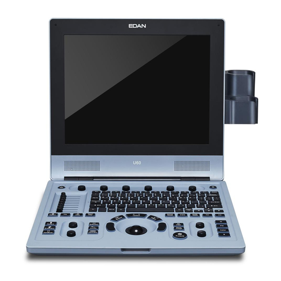
U60 Diagnostic Ultrasound System User Manual System Overview Chapter 3 System Overview 3.1. Appearance 3.1.1. Front View Figure 3-1 Front View 1. Display screen 2. Control panel 3. I/O ports NOTE: 1. Please check the details of I/O ports on Figure 4-7 I/O Ports on the Left Panel. -
Page 23: Rear View
U60 Diagnostic Ultrasound System User Manual System Overview 3.1.2. Rear View Figure 3-2 Rear View Handle Heat dissipation orifice Probe sockets Fuse-box Appliance inlet Equipotential terminal Probe holder Battery compartment door CAUTION Ensure system vents are clear and unobstructed. - 15... -
Page 24: Configuration
U60 Diagnostic Ultrasound System User Manual System Overview 3.2. Configuration 3.2.1. Standard Configuration 1 main unit 1 power cord 1 ground wire 2 pieces of fuse, φ5×20, T3.15AH250V 2 USB disks 1 hard disk ... - Page 25 U60 Diagnostic Ultrasound System User Manual System Overview For the probe C422UB, BGK-R20UB R20UB Needle Guide Bracket Kit Supports: 14G~23G For the probe L552UB, BGK-L50UB L50UB Needle Guide Bracket Kit Supports: 14G~23G For the probe C5-2b, BGK-C5-2 BGK-C5-2 Needle Guide Bracket Kit...
-
Page 26: Chapter 4 Installation Instructions
After unpacking the device, you should follow the packing list to check the product carefully and to make sure that no damage has occurred during transportation. For installation, please contact your local distributor or the EDAN service department at: support@edan.com.cn. -
Page 27: Installing And Uninstalling A Battery
U60 Diagnostic Ultrasound System User Manual Installation Instructions 4.3.1. Installing and Uninstalling a Battery To install a battery (if necessary): 1. Turn off the device, and take out the battery from the package. 2. Press the button on the battery compartment door and pull the door out. -
Page 28: Connecting And Disconnecting Probes
U60 Diagnostic Ultrasound System User Manual Installation Instructions To uninstall a battery: 1. Turn off the device, and press the button on the battery compartment door and pull the door out. 2. Turn the lever counterclockwise to hide it. 3. Pull the battery out. - Page 29 U60 Diagnostic Ultrasound System User Manual Installation Instructions The scan direction mark located at the side of probe indicates the beginning direction of scanning. The scan direction mark is shown below. Scan Direction Mark Figure 4-5 Probe Scan Direction Mark Schematic Diagram There is information about Model and SN on the probe connector.
-
Page 30: Peripheral Connections
Once the probe is connected to the main unit, please do not reinstall it frequently. This is to avoid poor contact between the probe and the main unit. 4.3.3. Peripheral Connections Video connections are located on the left panel of the U60. WARNING 1. Accessory equipment connected to the analog and digital interfaces must be certified according to the respective IEC/EN standards (e.g., IEC/EN 60950 for data... - Page 31 Installation Instructions CAUTION To ensure proper grounding and leakage current levels, it is the policy of EDAN to have an authorized EDAN representative or EDAN approved third party perform all on-board connections of documentation and storage devices to the U60.
-
Page 32: Equipotential Bonding
Any use of other devices with the system is at the user’s risk and may void the system warranty. In order to fulfill IEC/EN 60601-1 requirements, connections of peripheral equipment to the U60 must adhere to one of the following conditions: ... -
Page 33: Printer Installation
IEC/EN 60601-1. If in doubt, consult our technical service department or your local distributor. 5. If you want to use a multiple portable socket-outlet to supply power to the whole U60 system, you are suggested to calculate the system power consumption when building a U60 system so as to match the system power consumption with the power sustained by a multiple portable socket-outlet. -
Page 34: Chapter 5 System Control
U60 Diagnostic Ultrasound System User Manual System Control Chapter 5 System Control 5.1. Powering On/Off Device To power on the device Before powering on this device, check as below: 1. Check the potential equalization conductor and make sure it is connected properly. - Page 35 U60 Diagnostic Ultrasound System User Manual System Control To Switch Users If Password Protection is enabled, switching users is allowed without restarting the system. 1. Press Power on/off key, and the system will display a confirmation dialog box. 2. Select User from the confirmation dialog box. A login information dialog box will be displayed providing access to changing user.
-
Page 36: Examining
U60 Diagnostic Ultrasound System User Manual System Control The device displays the wrong information, and it lasts a long time. The device displays abnormally. The device can not execute an operation. 5.2. Examining Apply an appropriate amount of coupling gel (medical ultrasound coupling agent) to the body area to be examined, and then contact the area with the acoustic window of the probe firmly. -
Page 37: Screen Layout
U60 Diagnostic Ultrasound System User Manual System Control 5.3. Screen Layout ① ⑤ ③ ② ④ ⑥ ⑦ ⑧ Figure 5-1 Monitor Display ①Information Field: Manufacturer logo, Institution/Hospital name, Patient name, Patient ID, Current examination ③ type, Probe model, Probe frequency, “Freeze” icon, MI, TI, System date and time, etc. - Page 38 U60 Diagnostic Ultrasound System User Manual System Control ⑦Menu Controls Field: Image parameters adjustment/ program menus control, the items correspond to system menus in different modes or status. ⑧ Status Prompt Field: The lower left side of the field displays operation prompt, examination type;...
-
Page 39: Control Panel
U60 Diagnostic Ultrasound System User Manual System Control 5.4. Control Panel ① ⑥ ② ③ ⑤ ④ Figure 5-2 Control Panel ① Power/running indicators ② Power on/off key ③ TGC sliders ④ Function controls ⑤ PC keyboard ⑥ Menu Controls 5.4.1. -
Page 40: 0~9" Numeric Keys
U60 Diagnostic Ultrasound System User Manual System Control NOTE: 1. Please be gentle when running the trackball. 2. Please keep the surface of trackball clean. 5.4.2. “0~9” Numeric Keys Numbers are used for time calibrating, data setting, age notating, and comment adding, etc. - Page 41 U60 Diagnostic Ultrasound System User Manual System Control Glide the slide controls to adjust the TGC, glide the upper segments to adjust the near field gain, and the lower segments to adjust the far field gain; glide rightward to increase TGC, and glide leftward to decrease.
- Page 42 U60 Diagnostic Ultrasound System User Manual System Control 1. Press to toggle between current image modes in duplex or triplex. 2. After the image is frozen, the system enters Cine Review status by default. Press Active Mode to switch between different frozen imaging modes and Cine Review status.
- Page 43 U60 Diagnostic Ultrasound System User Manual System Control Generic Measurement key Generic Press to activate or exit the generic measurement Measurement function. 1. In annotation status, press to display the comment library. 2. In measuring status, you can press Update once to...
- Page 44 U60 Diagnostic Ultrasound System User Manual System Control Rotate the Gain button to increase or decrease Gain the overall gain of the current mode. In real time mode, rotate the Depth button to Depth adjust depth. File management key Press this key to enter or to exit the file management system.
- Page 45 U60 Diagnostic Ultrasound System User Manual System Control Press to decrease brightness. And the brightness symbol will be displayed at the bottom of the screen. Press to increase brightness. And the brightness symbol will be displayed at the bottom of the screen.
-
Page 46: Imaging Functions
U60 Diagnostic Ultrasound System User Manual System Control Page down: You can press on menu controls panel to flip through pages of the menu controls field. Press the key again, and it returns to the first page circularly if the current page is the last one. - Page 47 U60 Diagnostic Ultrasound System User Manual System Control Color mode Imaging Control Follow the same procedure as described under B Mode to locate the anatomical area of interest. After optimizing the B mode image, press Color, move the scan area of interest as close to the center of the image as possible;...
- Page 48 U60 Diagnostic Ultrasound System User Manual System Control Dual-split mode of B+Color/PDI: In dual-split mode of 2B, press Color/PDI, and then press to enter dual-split mode of B+Color/PDI, the two windows are in B+Color/PDI mode. In single B+Color/PDI mode, press to enter dual-split mode of B+Color/PDI, the two windows are in B+Color/PDI mode.
- Page 49 U60 Diagnostic Ultrasound System User Manual System Control Figure 5-4 Example of B+Color+PW Scan In B+PW mode, you can choose scanning in synchronized or unsynchronized mode by pressing Duplex/Triplex menu control: in unsynchronized mode, the active mode is PW; while, in synchronized mode, the B and PW mode are both active.
- Page 50 U60 Diagnostic Ultrasound System User Manual System Control After entering B+PW, or B+Color/PDI+PW mode, in unsynchronized mode, roll the trackball to move the sample line and sample area, the B or B+Color/PDI image is active, and PW image is frozen; when the trackball stops moving, the B or B+Color/PDI image is frozen, and PW image is active.
- Page 51 U60 Diagnostic Ultrasound System User Manual System Control NOTE: 1. The HPRF mode is possible with C5-2b, P5-1b and L15-7b probes only. 2. The HPRF mode can be activated only in real-time mode. 3. The HPRF mode is available according to the following table. At each sample volume depth, HPRF will first occur at the scale range and PRF listed.
-
Page 52: Menu
U60 Diagnostic Ultrasound System User Manual System Control CW mode Display Control To enter CW mode: 1. In B or B+Color/ PDI/ DPDI mode, adjust image parameters; 2. Press CW to display sample line, move the trackball left or right to position the sample line in the region of interest, move the trackball up or down to adjust the depth of focus;... - Page 53 U60 Diagnostic Ultrasound System User Manual System Control Figure 5-5 B Mode Imaging Menu Measurement and calculation menu: Perform an operation. For instance, begin a distance measurement, and then the measurement cursor is displayed. The following are generic and application measurement and calculation menus.
- Page 54 U60 Diagnostic Ultrasound System User Manual System Control Figure 5-7 Obstetric Measurement and Calculation Menu in B mode Submenu: The symbol “►” indicates that there is a submenu associated with the menu option. Roll the trackball to highlight the menu option with “►”, the system displays a submenu for the selected option.
-
Page 55: Dialog Box Operation
U60 Diagnostic Ultrasound System User Manual System Control 5.6. Dialog Box Operation The dialog box may have a few tabs, as shown below. You can select one tab at a time with trackball and Set. Also, you can modify the parameter following the prompt instruction, and then highlight OK and press Set to save the modified parameters and close the dialog box;... -
Page 56: Presetting
U60 Diagnostic Ultrasound System User Manual System Control 5.7. Presetting 5.7.1. Entering Presetting Press Set up, and the system displays the preset menu, as shown below. Figure 5-10 Preset Menu 5.7.2. Displaying / Modifying Presetting Parameters Select a type of preset and press Set to display the relevant dialog box, and you can modify the parameter following the prompt instruction. - Page 57 U60 Diagnostic Ultrasound System User Manual System Control Figure 5-11 System Preset Dialog Box Preset items Options Functions Set hospital name displayed on the top Hospital Name Input freely left of the screen and diagnosis report. Chinese, English, etc.(The language...
- Page 58 U60 Diagnostic Ultrasound System User Manual System Control sleep mode (5-60 min), then screensaver is displayed and acoustic output is disabled. Set the grade of refresh speed during Refresh Speed 1-10 system dormancy. Set the color of the comment when...
-
Page 59: Probe Preset
U60 Diagnostic Ultrasound System User Manual System Control 5.7.4. Probe Preset In preset menu, move the cursor to highlight Probe Preset and press Set to display Probe preset dialog box, as shown below. Figure 5-12 Probe Preset Dialog Box The Probe preset dialog box displays probe selection and Exam mode selection. This page is used to assign an exam type to a specific probe. -
Page 60: Exam Preset
U60 Diagnostic Ultrasound System User Manual System Control 3. Arrange the sequence of the associated exams: after the exams associated with the probe are set, you can select an exam, and click on to adjust the sequence of it gradually. -
Page 61: Image Parameter Preset
U60 Diagnostic Ultrasound System User Manual System Control prompt “Delete the exam?” Click on Yes to delete the exam, or click on No to exit. To add an exam: Press Add to display the Add new Exam Mode dialog box, as shown below. - Page 62 U60 Diagnostic Ultrasound System User Manual System Control Figure 5-15 Image Parameter Preset Dialog Box The Exam Mode field on the left side of the dialog box displays all exam modes supported by the probe. While the right side of the dialog box displays all parameter settings for the probe in different image modes.
- Page 63 U60 Diagnostic Ultrasound System User Manual System Control curve map Rejection Set the default rejection Scan Mode HiDen/HiFPS Set the default scan mode Depth 1.9 cm-32.4 cm(C5-2b) Set the default examine depth Scan Angle 0/1/2/3 Set the default scan angle...
- Page 64 U60 Diagnostic Ultrasound System User Manual System Control 0-15, 0.9kHz-14.7kHz Set the default PRF in PW mode WallFilter Set the default wallfilter in PW mode Dyn Rng 30-90, in increments of 2 Set the default dynamic range of PW mode Sample Volume 0.5-20.0...
-
Page 65: Measurement Preset
U60 Diagnostic Ultrasound System User Manual System Control Figure 5-16 Default Image Mode Preset Dialog Box 5.7.7. Measurement Preset In the preset menu, move the cursor to highlight Measure Preset and press Set to display Measure Preset dialog box, as shown below:... - Page 66 U60 Diagnostic Ultrasound System User Manual System Control Figure 5-17 Measure Preset Dialog Box Parameter References Parameter References Tokyo Tokyo Hellman Hadlock Rempen Hansmann China China Robinson Tokyo Tokyo Hadlock Hadlock1 Merz Hadlock2 Rempen Hadlock3 Osaka Hadlock4 China Shepard Hansmann...
-
Page 67: Comment Preset
U60 Diagnostic Ultrasound System User Manual System Control Osaka Hansmann Hadlock, Merz, Hansmann Jeanty Osaka Goldstein Hansmann Oriental, Occidental 40 weeks/41 weeks Table 5-8 Measurement Preset Information 5.7.8. Comment Preset The comment library includes eight tabs: Abd, OB, Sml, Gyn, Ped, Card, Uro, and Vas. Each tab has a few sets of comments defined at the factory, and you can create up to 16 user-defined comments for each tab by using the Add button. - Page 68 U60 Diagnostic Ultrasound System User Manual System Control To create user-defined comments (take Abd tab for instance): 1. Press Abd tab to open the Abd comment library. 2. Roll the trackball to the Comment editable filed in the Custom Comment box, and press Set.
-
Page 69: Preset Data
U60 Diagnostic Ultrasound System User Manual System Control 2. Roll the trackball to highlight a user-defined comment, and press Set. 3. Press Del to delete the comment. 4. Press OK to save the modification, or press Cancel to give up and close the dialog box. -
Page 70: Connectivity
U60 Diagnostic Ultrasound System User Manual System Control 5.7.10. Connectivity Press Set up, roll the trackball to highlight Connectivity, and press Set. Then the Connectivity dialog box is displayed, as shown below. Figure 5-21 Connectivity Preset Item Description System AE Title... -
Page 71: Maintenance
3. Anti-virus software is not installed on this device. Please take anti-virus measures in the network environment where your ultrasound systems are used. 5.7.11. Maintenance The maintenance can be only done by EDAN authorized personnel. Operations such as installing DICOM and upgrading software can be accessed on the maintenance menu. - 63... -
Page 72: System Information
U60 Diagnostic Ultrasound System User Manual System Control 5.7.12. System Information In the preset menu, move the cursor to highlight System Info and press Set to display System information interface. 5.7.13. User Login Press Set up, roll the trackball to highlight User, and press Set. Then the User dialog box is displayed, as shown below. - Page 73 U60 Diagnostic Ultrasound System User Manual System Control Click the an user to select it for editing operation Table 5-10 User Login Presetting Information User type includes Administrator and Operator. Administrator users have authority to enable/disable password protection, add/delete/edit users and can view all exams in the patient database.
-
Page 74: Printing
4. Before printing, make sure the printer power cord and the USB cable are connected well. 5. Do not cut off the printer power supply or the USB cable during printing. 6. If the printer can not work normally, please restart the printer and the U60. - 66... - Page 75 U60 Diagnostic Ultrasound System User Manual System Control To use the print proxy function for graph/text report printing: The print proxy function allows you to connect the ultrasound system with a PC, and then all the graph/text report printing work can be done by the graph/text printers connected to the PC, which provides you wide choices of printers for graph/text report printing.
-
Page 76: Chapter 6 Operation
U60 Diagnostic Ultrasound System User Manual Operation Chapter 6 Operation 6.1. Entering or Editing Patient Information NOTE: Before a patient exam, EndExam should be pressed. Pressing EndExam will automatically erase all cache memory (Including patient data, comments, measurements, calculations and reports of the last exam,except for archived Images.) CAUTION To avoid patient information errors, always check the information with the patient. -
Page 77: Selecting A Probe And An Examination Type
U60 Diagnostic Ultrasound System User Manual Operation 6.2. Selecting a Probe and an Examination Type Connect a probe to the system, and press Transducer to open a dialog box as shown in the figure below. Roll the trackball to select the desired exam type corresponding to the probe, such as abdominal, obstetrics, gynecology, pediatric, small parts, urology, peripheral vascular, musculoskeletal (conventional and superficial), and cardiac exams. -
Page 78: Selecting An Imaging Mode
The system will display the default mode after it is powered on. You can select an imaging mode by pressing , or and then begin an examination. 6.4. Image Adjustments The U60 also provides the following additional control functions, which are available through status menus and Menu Controls panel. Control Description Parameter Range Operations... - Page 79 U60 Diagnostic Ultrasound System User Manual Operation This function is used to increase target signals, weaken the speckle Spatial Comp noises, enhance image contrast of (Spatial the target area, and decrease On/Off Compounding influences sound shadow, Imaging) ultrasound loss and the occurrence of reverberation.
- Page 80 U60 Diagnostic Ultrasound System User Manual Operation Control Description Parameter Range Operations Functions CFM: Increase the overall strength of color flow echoes, but the color map will not be affected. 1-80, Gain PDI: Power Doppler Imaging. The Gain knob in increments of 1...
- Page 81 U60 Diagnostic Ultrasound System User Manual Operation Reverse the color of blood flow. Off: Red toward (positive velocities) Invert On/Off and Blue away(negative velocities) On: opposite to the above. Adjust the velocity range of forward flow /reverse flow. Minimize aliasing...
- Page 82 U60 Diagnostic Ultrasound System User Manual Operation Control Description Parameter Range Operations Functions Increases or decreases the amount 1-80, Gain of echo information. It may brighten Gain knob in increments of 1 or darken the PW mode image. sample volume...
- Page 83 U60 Diagnostic Ultrasound System User Manual Operation colorization conventional B/PW mode image to Pseudo Color enhance the visibility so as to 6 types distinguish B, M and PW mode intensity. The echoes information in the sample volume is used to evaluate Sample Volume spectral.
- Page 84 U60 Diagnostic Ultrasound System User Manual Operation Control Description Parameter Range Operations Functions Increases or decreases the amount 1-80, Gain of echo information. It may brighten Gain knob in increments of 1 or darken the CW mode image. Position of sample...
- Page 85 U60 Diagnostic Ultrasound System User Manual Operation Insulate the Doppler signal from excessive noise caused from vessel WallFilter movement The bigger the value, the more low velocity signals will be Menu controls filtered out. Adjust the scanning speed level of Sweep Speed the CW mode image.
-
Page 86: Generic Measurements And Calculations
U60 Diagnostic Ultrasound System User Manual Operation Save image parameter preset: 1. After the image parameter adjustments, press Save Preset Data key (user-defined key F1/F2/F3/F4). 2. Press OK in the “Save current image parameters data?” dialog box. 3. Press OK in the “Overwrite the current exam preset data?” dialog box to save the image parameter preset to the current exam mode;... -
Page 87: Generic Measurements In B Mode
U60 Diagnostic Ultrasound System User Manual Operation 6.5.1. Generic Measurements in B Mode The default measurement of B mode is distance measurement. B mode measurement menus are shown as follows: Figure 6-3 B Mode Generic Measurement and Calculation Menu Distance To measure distance: 1. - Page 88 U60 Diagnostic Ultrasound System User Manual Operation axis of ellipse. 4. Roll the trackball and press Set to anchor the end point of fixed axis of ellipse. 5. Roll the trackball, and press Set to define the size of the ellipse.
- Page 89 U60 Diagnostic Ultrasound System User Manual Operation measurement. You can measure a maximum of eight groups of data. The outcome will be displayed in the measurement result window, as shown below. 6. Press Caliper to finish and exit. Trace1 Circ...
- Page 90 U60 Diagnostic Ultrasound System User Manual Operation and then freeze it. 4. Measure the length of the third axis in the vertical section image with the distance measurement method. The outcome will be displayed in the measurement result window. In the 2B mode or 4B mode To measure volume: 1.
- Page 91 U60 Diagnostic Ultrasound System User Manual Operation 2. Measure the length and the width. 3. Unfreeze the system to acquire a new image (vertical-section image), and then freeze it. 4. Measure the height. The outcome will be displayed in the measurement result window.
- Page 92 U60 Diagnostic Ultrasound System User Manual Operation the system interchanges the numerator and denominator. 6. Roll the trackball and press Set to complete the measurement, and the calculation result will be displayed in the measurement result window. 7. Roll the trackball and press Set to begin a new ratio measurement.
- Page 93 U60 Diagnostic Ultrasound System User Manual Operation 6. Roll the trackball and press Set to complete the measurement, and the calculation result will be displayed in the measurement result window. 7. Roll the trackball and press Set to begin a new stenosis measurement.
- Page 94 U60 Diagnostic Ultrasound System User Manual Operation 7. Press Caliper to finish and exit. Figure 6-11 Area Stenosis Measurement and the Results Angle To determine an angle, draw two lines: A and B. The system calculates the angle. To measure angle: 1.
- Page 95 U60 Diagnostic Ultrasound System User Manual Operation 1 Angle Dist1 Dist2 Angle 2Angle Dist1 Dist2 Angle Figure 6-12 Angle measurement The image will be frozen automatically after entering histogram Histogram measurement. 1. Press Caliper to activate generic measurement function. 2. Roll the trackball to highlight menu Histogram, and then press Set to activate a measurement cursor on the screen.
-
Page 96: Generic Measurements In M Mode
U60 Diagnostic Ultrasound System User Manual Operation 6.5.2. Generic Measurements in M Mode M mode measurements and calculations include distance, time, slope and heart rate (2 cycles). These are for B+M and M display modes only. The default measurement of B+M and M mode is heart rate measurement. - Page 97 U60 Diagnostic Ultrasound System User Manual Operation interval and then press Set. 5. Roll the trackball and press Set to begin a new time measurement. You can measure a maximum of eight groups of data. The outcome will be displayed in the measurement result window, as shown below.
-
Page 98: Generic Measurements In Color/Pdi Mode
U60 Diagnostic Ultrasound System User Manual Operation and then press Set to anchor start position, and the measurement mark turns to a vertical line. 4. Roll the trackball to move the second measurement maker on the peak systole following two complete cycles and then press Set to anchor end position. - Page 99 U60 Diagnostic Ultrasound System User Manual Operation NOTE: Heart rate and time measurement methods are the same as those in the M mode. Reference Section 6.5.2 Generic Measurements in M Mode. To measure velocity of a point on the Doppler wave: Velocity 1.
- Page 100 U60 Diagnostic Ultrasound System User Manual Operation 3. Roll the trackball and press Set to anchor the first peak point, measuring Vel1. 4. Roll the trackball and press Set to anchor the second peak point, measuring Vel2, calculating RI. 5. Roll the trackball and press Set to begin a new RI measurement. You can measure a maximum of eight groups of data.
- Page 101 U60 Diagnostic Ultrasound System User Manual Operation Auto The trace in PW mode is shown below: (Auto trace) Figure 6-19 Trace Diagram Where, VPS is the maximum velocity in the cycle; VED is the velocity at the end of diastole;...
-
Page 102: Application Measurements And Calculations
U60 Diagnostic Ultrasound System User Manual Operation 6.6. Application Measurements and Calculations To enter application measurements and calculations menu, select a probe and the examination type and press Measure, then you can choose the measurement item you need. Please find more... -
Page 103: Worksheet (Report)
U60 Diagnostic Ultrasound System User Manual Operation The system-defined examinations are abbreviated as follows: Abd: Abdominal; OB: Obstetric; Sml: Small Parts; Gyn: Gynecology; PED: Pediatrics Urol: Urology; Vas: Vascular After entering the application measurement, the first item of the measurement menu is activated by default. -
Page 104: Comment Function
U60 Diagnostic Ultrasound System User Manual Operation To edit the worksheet: Move the trackball to the text box and edit the worksheet. Press OK to save. To add images to the report: Press Image in the worksheet dialog box to add at most four images to the report. - Page 105 U60 Diagnostic Ultrasound System User Manual Operation To add a comment by using the comment library: 1. Press Comment, and there is a cursor “І” displayed in the image area for annotating; 2. Press Update, the system displays the comment library of current exam by default. You can switch to other tabs by moving the trackball and pressing Set;...
- Page 106 U60 Diagnostic Ultrasound System User Manual Operation Figure 6-20 System-defined Comment Library - 98...
-
Page 107: Body Mark Function
U60 Diagnostic Ultrasound System User Manual Operation 6.9. Body Mark Function To add a body mark: 1. Press Body Mark, the system displays the Body Mark dialog box of current exam by default. You can switch to other tabs by moving the trackball and pressing Set. The often-used body marks are listed under each tab, and you can press More to enter the page of seldom-used body marks and press Back to return to the page of often-used body marks. -
Page 108: Zoom
U60 Diagnostic Ultrasound System User Manual Operation Figure 6-21 System Body Mark Library (Abd tab) 6.10. Zoom Zoom is used to magnify images for better viewing. To zoom in real-time/frozen B mode: In real-time or frozen B mode, press Zoom knob, and the system displays a zooming window in the middle of the image;... -
Page 109: Cine Review
U60 Diagnostic Ultrasound System User Manual Operation displays a zooming window, rotate the zooming adjustment knob to adjust magnification factor, and press Set to enter the zoomed status. But in the zoomed B+C status, the ROI cannot be displayed or moved. - Page 110 U60 Diagnostic Ultrasound System User Manual Operation To perform the automatic playback: 1. Press Freeze to freeze the image, and the system displays the cine menu. 2. Set the start frame: in manual playback status, roll the trackball to review frame by frame...
-
Page 111: File Management
U60 Diagnostic Ultrasound System User Manual Operation 6.12. File Management Press File to display the file menu, as shown below. Figure 6-24 File Menu (the left—with no DICOM installed, the right—with DICOM installed) 6.12.1. Saving Files Clip types: The clip types include CIN and AVI. - Page 112 U60 Diagnostic Ultrasound System User Manual Operation Set repeatedly to cycle between JPG, BMP, FRM and DCM (if DICOM is installed). To save a file: The system provides two ways to save images: Press Store Image or Store Clip on thecontrol pannel;...
- Page 113 U60 Diagnostic Ultrasound System User Manual Operation Save As When obtaining a satisfying image: 1. Press File and select Save As…in the file menu to display the File Save As dialog box. 2. Select a destination drive from the Drive pull-down menu, and a folder from the directory on the left, or press New Folder to create a folder for storing files.
-
Page 114: File Manager
U60 Diagnostic Ultrasound System User Manual Operation 6.12.2. File Manager You can use the file manager to perform the file management or browse the images. In real-time or frozen status, press File to display file menu, and select File Manager, the File Manager dialog box pops up, as shown below. - Page 115 U60 Diagnostic Ultrasound System User Manual Operation NOTE: 1. When you are sending, deleting or renaming a file, do not connect or disconnect the USB disk. 2. USB disk must be in FAT32 format, while hard disk must be in EXT2 format.
-
Page 116: Sending Files
U60 Diagnostic Ultrasound System User Manual Operation To open files 1. Select a desired drive from the Drive pull-down menu and file format, and then press Set. 2. Point to the file that needs to be opened and press Set, press Open or double click on the file, a prompt Loading file…... - Page 117 U60 Diagnostic Ultrasound System User Manual Operation Figure 6-27 File Menu (with DICOM Function) To send a DCM Image 1. Highlight the submenu DCM Image, and then press Set. 2. If the server is running normally, the current image will be sent to the server.
-
Page 118: Needle Guide Function
EDAN customer engineer. 3. The displayed needle guide pathway on the EDAN video monitor is intended for reference during biopsy procedures. A variety of factors outside EDAN’s control, such... -
Page 119: Installing Needle Guide Bracket
U60 Diagnostic Ultrasound System User Manual Operation needle guide components, please contact your EDAN customer engineer before using it. 6.13.1. Installing Needle Guide Bracket WARNING 1. For illustration purpose only, transducer and bracket may be shown without a protective sheath. Always place a protective sheath on transducer and bracket to protect cross infection. - Page 120 U60 Diagnostic Ultrasound System User Manual Operation 3. Secure the angle knob. 4. Press the tab release and place the biopsy needle into the needle guide path. Use the adjusting knob to properly secure the needle. 5. After biopsy, press the tab release to remove the needle, and loosen the locking knob to remove the bracket from the transducer.
- Page 121 U60 Diagnostic Ultrasound System User Manual Operation BGK-CR10UA Structures: Needle Guide Path Locking Knob Clamp Installation and Use Steps: 1. Place an appropriate amount of gel on transducer surface, and insert transducer into the sheath. 2. Loosen the locking knob to open the clamp of bracket. Attach the bracket to the transducer by aligning the locating markers on the bracket and the transducer.
-
Page 122: Activating Needle Guide Function
U60 Diagnostic Ultrasound System User Manual Operation 6.13.2. Activating Needle Guide Function To enable the needle guide function: In the real-time or measurement state of B mode imaging, press File on the keyboard, highlight Needle Guide and then press the Set to activate Needle Guide function. -
Page 123: To Display Or To Hide The Needle Guide Line
U60 Diagnostic Ultrasound System User Manual Operation 6.13.4. To Display or To Hide the Needle Guide Line Highlight Display in the needle guide menu, and press the Set key repeatedly to display or to hide the needle guide line. 6.13.5. To Adjust the Needle Guide Line Needle guide line has been verified when the device is produced. -
Page 124: Performing Puncture Function
U60 Diagnostic Ultrasound System User Manual Operation 6.13.6. Performing Puncture Function To perform puncture: The needle guide line is displayed on the image of the ultrasound system, and the numbers on the right of the menu stand for the situation of puncture;... -
Page 125: Chapter 7 Abdominal Measurements & Calculations
U60 Diagnostic Ultrasound System User Manual Abdominal Measurements and Calculations Chapter 7 Abdominal Measurements & Calculations 7.1. Measurements and Calculations The abdominal examination is usually performed in the B mode. 1. Press Transducer, select the desired probe model and the exam mode Abdomen/ Abd Difficult/ Aorta, and then press OK, or double click on the exam type. -
Page 126: Pancreatic
U60 Diagnostic Ultrasound System User Manual Abdominal Measurements and Calculations measurement. Reference Section 6.5.1Generic Measurements in B Mode. 3. After the measurement, the result of gallbladder will be displayed in the measurement result window. 7.1.3. Pancreatic 1. In the abdominal measurement menu, roll the trackball to highlight Pancreatic, select Panc Duct/ Panc Head/ Panc Body/ Panc Tail from the submenu, and then press Set. - Page 127 U60 Diagnostic Ultrasound System User Manual Abdominal Measurements and Calculations Figure 7-2 Abdominal Worksheet The diagnosis editing column displays the cursor “І”, and you can enter diagnosis information. For specific operations of editing or printing the report, please refer to Section 6.7 Worksheet(Report).
-
Page 128: Chapter 8 Obstetric Measurements And Calculations
U60 Diagnostic Ultrasound System User Manual Obstetric Measurements and Calculations Chapter 8 Obstetric Measurements and Calculations The obstetric examination is usually performed in the B mode, PW mode, and M mode. 8.1. Obstetric Measurements and Calculations in B Mode To enter B mode obstetric examination: 1. - Page 129 U60 Diagnostic Ultrasound System User Manual Obstetric Measurements and Calculations BBT: Basal Body Temperature EFW: Estimated Fetal Weight B-OB MEAS 1: Label Description Channel Method Results display Single Axis, 2-Axis, Gestational Sac Diameter 3-Axis Crown Rump Length Nuchal Translucency...
-
Page 130: Crl
U60 Diagnostic Ultrasound System User Manual Obstetric Measurements and Calculations 8.1.1. GS 1. In the B-Obstetric measurement menu, roll the trackball to highlight the menu GS, Select Single, 2-Axis or 3-Axis, press Set, and move the cursor to image and display “+”. For 2-Axis and 3-Axis, it is required to measure the length of two and three axis of GS respectively, and the MA and EDD are calculated from average GS measurement results. -
Page 131: Bpd
U60 Diagnostic Ultrasound System User Manual Obstetric Measurements and Calculations 4. To begin a new NT measurement, repeat steps 1 through 3. You can measure a maximum of one group of data. 8.1.4. BPD To measure BPD: 1. In the B-Obstetric measurement menu, roll the trackball to highlight the menu BPD, press Set, and move the cursor to image and display “+”. -
Page 132: Afi
U60 Diagnostic Ultrasound System User Manual Obstetric Measurements and Calculations 3. The results are displayed in measurement result window. 4. To begin a new AC measurement, repeat steps 1 through 3. You can measure a maximum of one group of data. -
Page 133: Apad
U60 Diagnostic Ultrasound System User Manual Obstetric Measurements and Calculations Reference Section 6.5.1Generic Measurements in B Mode. 3. The results are displayed in measurement result window. 4. To begin a new TAD measurement, repeat steps 1 through 3. You can measure a maximum of one group of data. -
Page 134: Fta
U60 Diagnostic Ultrasound System User Manual Obstetric Measurements and Calculations 2. Measure CER by the method of distance measurement. Reference Section 6.5.1Generic Measurements in B Mode. 3. The results are displayed in measurement result window. 4. To begin a new CER measurement, repeat steps 1 through 3. You can measure a maximum of one group of data. -
Page 135: Fbp
U60 Diagnostic Ultrasound System User Manual Obstetric Measurements and Calculations Set, and move the cursor to image and display “+”. 2. Measure THD by the method of distance measurement. Reference Section 6.5.1Generic Measurements in B Mode. 3. The results are displayed in measurement result window. -
Page 136: Edc Calculation
U60 Diagnostic Ultrasound System User Manual Obstetric Measurements and Calculations FBP Report 1. In the B-Obstetric measurement menu, roll the trackball to highlight the menu FBP, select FBP Report and press Set to get the FBP report window. 2. Press Cancel to exit. -
Page 137: Efw Calculation
U60 Diagnostic Ultrasound System User Manual Obstetric Measurements and Calculations 4. Select OK and press Set to do the calculation automatically, or Cancel to give up the calculation. NOTE: 1. For EDC calculation, make sure that the system date is correct. The standard pregnancy period in the system can be set to 40 or 41 weeks. -
Page 138: Obstetric Measurements And Calculations In Pw Mode
U60 Diagnostic Ultrasound System User Manual Obstetric Measurements and Calculations Measurement Measurement items vary with formulas. So you should perform the measurement items according to the preset formula. Take Osaka formula, for instance, to calculate EFW: EFW = 1.25674* (BPD ) + 3.50665*FTA*FL+6.3... -
Page 139: Fhr
U60 Diagnostic Ultrasound System User Manual Obstetric Measurements and Calculations Ductus V: Ductus Venosus Table 8-4 Obstetric Measurements in PW Mode 8.2.1. FHR To measure FHR: 1. In the PW-Obstetric measurement menu, select FHR. 2. Measure FHR by the method of heart rate measurement. -
Page 140: Fetal Ao
U60 Diagnostic Ultrasound System User Manual Obstetric Measurements and Calculations 8.2.4. Fetal AO To measure Fetal AO: 1. In the PW-Obstetric measurement menu, select Fetal AO. 2. Measure Fetal AO by the method of D trace measurement. Reference Section 6.5.4 Generic Measurements in D Mode. -
Page 141: Ductus V
U60 Diagnostic Ultrasound System User Manual Obstetric Measurements and Calculations 8.2.7. Ductus V To measure Ductus V: 1. In the PW-Obstetric measurement menu, select Ductus V. 2. Measure Ductus V by the method of D trace measurement. Reference Section 6.5.4 Generic Measurements in D Mode. -
Page 142: Growth Curve
U60 Diagnostic Ultrasound System User Manual Obstetric Measurements and Calculations 8.4.1. Growth Curve You can define the fetus growth by comparing the measured parameter value with the fetus growth curve. Operation procedure: 1. Measure one or more fetus growth parameters (GS, CRL, BPD, FL, AC, HC, CER, FTA, HUM, or THD). -
Page 143: Obstetric Report
U60 Diagnostic Ultrasound System User Manual Obstetric Measurements and Calculations Figure 8-6 Fetal Growth Curve (Four) NOTE: Press Single/Four to display single growth graphics or four growth graphics. 8.4.2. Obstetric Report After obstetric examination, the system will generate an obstetrical diagnosis worksheet automatically. - Page 144 U60 Diagnostic Ultrasound System User Manual Obstetric Measurements and Calculations Figure 8-7 Obstetric Worksheet The diagnosis editing column displays the cursor “І”, and you can enter diagnosis information. NOTE: The system will display the completed measurements and calculations; the uncompleted measurements and calculations will not be displayed.
-
Page 145: Chapter 9 Cardiac Measurements And Calculations
U60 Diagnostic Ultrasound System User Manual Cardiac Measurements and Calculations Chapter 9 Cardiac Measurements and Calculations The cardiac examination is usually performed in the B mode, B+M mode or PW mode. Press Transducer, select the desired probe model and the exam mode Adult Cardiac/ Pedia Cardiac, and then press OK, or double click on the exam type. - Page 146 U60 Diagnostic Ultrasound System User Manual Cardiac Measurements and Calculations 1. CUBE formula: NOTE: d: end diastolic; s: end systolic Label Description Method LVIDd Left Ventricle Internal Diameter Distance (mm) LVIDs Left Ventricle Internal Diameter Ejection Time Time (ms or s)
- Page 147 U60 Diagnostic Ultrasound System User Manual Cardiac Measurements and Calculations 2. TEICHHOLZ formula: NOTE: d: end diastolic; s: end systolic Label Description Method LVIDd Left Ventricle Internal Diameter Distance (mm) LVIDs Left Ventricle Internal Diameter Distance (mm) Ejection Time Time (ms or s)
- Page 148 U60 Diagnostic Ultrasound System User Manual Cardiac Measurements and Calculations Aortic Valve Volume Opened, MAVO1 beginning Aortic Valve Volume Opened, Distance (mm) MAVO2 ending Aortic Amplitude LVMW (g) =1.04* ({IVSTd (cm)+LVIDd (cm)+LVPWd LVMW Left Ventricular Muscle Weight (cm)} -LVIDd (cm) )-13.6...
- Page 149 U60 Diagnostic Ultrasound System User Manual Cardiac Measurements and Calculations Left Ventricular Muscle Weight LVMWI LVMWI (No unit)=LVMW/BSA Index The ratio of CA to CE A/E (No unit)= CA (mm)/CE (mm) Left Atrium Diameter / Aortic LAD/AOD LAD/AOD (No unit)= LAD (mm)/AOD (mm)
- Page 150 U60 Diagnostic Ultrasound System User Manual Cardiac Measurements and Calculations Move the cursor to the end systolic of the left ventricle, and then measure LVIDs. The method is the same as the generic M mode distance measurement method. LVIDs, ESV, SV, EF, and FS will be displayed in the measurement result window.
-
Page 151: Mitral Valve
U60 Diagnostic Ultrasound System User Manual Cardiac Measurements and Calculations Figure 9-4 Height and Weight Input Dialog Box Input suitable values in the Height and Weight boxes. Roll the trackball to highlight OK and press Set. The measurements and calculations of all the LV parameters are as below. -
Page 152: Aorta
U60 Diagnostic Ultrasound System User Manual Cardiac Measurements and Calculations Measurement operation procedure: In the M-cardiac measurement menu, roll the trackball to highlight Mitral to display the submenu. Roll the trackball to highlight Valve Volume, and press Set. Measure DEV, by the method of generic M mode slope measurement. -
Page 153: Cardiac Measurements And Calculations In B Mode
U60 Diagnostic Ultrasound System User Manual Cardiac Measurements and Calculations window. The system will display LVWMI if you have keyed in Height and Weight before the measurement. If you had measured LV before, it will renovate the LV results. 9.2. Cardiac Measurements and Calculations in B Mode Press Transducer, select the desired probe model and the exam mode Adult Cardiac/ Pedia Cardiac, and then press OK, or double click on the exam type. - Page 154 U60 Diagnostic Ultrasound System User Manual Cardiac Measurements and Calculations Heart Rate Key in (bpm) /LVLd End Diastolic Volume EDV (mL)= (8/3π)×{LVALd (mm (mm) /1000 /LVLs End Systolic Volume ESV (mL)= (8/3π)×{LVALs (mm (mm) /1000 Stroke volume SV (mL)=EDV (mL)-ESV (mL) Cardiac Output CO (L/min)= SV (mL) ×...
- Page 155 U60 Diagnostic Ultrasound System User Manual Cardiac Measurements and Calculations Stroke Index SI (No unit)= SV (mL)/ BSA (m Cardiac Index CI (No unit)= CO (L/min)/ BSA (m Body Surface Area Calculate by the selected formula (m Table 9-7 Measurement and Calculation Items with Dual Plane Ellipse Formula 3.
- Page 156 U60 Diagnostic Ultrasound System User Manual Cardiac Measurements and Calculations LVLd Left Ventricular Length Distance (mm) Left Ventricular Fractional Area of LVAPd Papillary Muscles Ellipse Area (mm , cm , or dm LVAMs Left Ventricular Anterior Wall LVLs Left Ventricular Length...
- Page 157 U60 Diagnostic Ultrasound System User Manual Cardiac Measurements and Calculations Measurement items: LVLd, LVALd , LVLs and LVALs, To measure LV: 1. In the B-cardiac measurement menu, roll the trackball to highlight LV. Then select S-P Ellipse and press Set.
- Page 158 U60 Diagnostic Ultrasound System User Manual Cardiac Measurements and Calculations To calculate MVCF: 1. Move the cursor to Input. Then select the submenu LVET and press Set to display an ET input dialog box, as shown below. Figure 9-7 ET Input Dialog Box 2.
-
Page 159: Rv (Right Ventricle Internal Diameter)
U60 Diagnostic Ultrasound System User Manual Cardiac Measurements and Calculations 9.2.2. RV (Right Ventricle Internal Diameter) 1. In the B-cardiac measurement menu, roll the trackball to highlight RV. 2. Measure RV by the method of distance. 3. The result will be displayed in the measurement result window. - Page 160 U60 Diagnostic Ultrasound System User Manual Cardiac Measurements and Calculations For the steps of heart rate, time and slope measurement, please refer to Section 6.5.2 Generic Measurement in M mode. To measure PG of a point on the Doppler wave:...
-
Page 161: Cardiac Report
U60 Diagnostic Ultrasound System User Manual Cardiac Measurements and Calculations backwards. 4. Press Set to anchor the end point, the system displays the results of Mean velocity, MeanPG, and VTI (Velocity Time Integral), etc. in measurement result window. 5. Roll the trackball and press Set to begin a new trace. You can measure a maximum of eight groups of data. - Page 162 U60 Diagnostic Ultrasound System User Manual Cardiac Measurements and Calculations The diagnosis editing column displays the cursor “І”, and you can enter diagnosis information. For specific operations of editing or printing the report, please refer to Section 6.7 Worksheet(Report). - 154...
-
Page 163: Chapter 10 Gynecology Measurements & Calculations
U60 Diagnostic Ultrasound System User Manual Gynecology Measurements and Calculations Chapter 10 Gynecology Measurements & Calculations The gynecology examination is usually performed in the B mode and PW mode. 10.1. Measurements and Calculations in B Mode 1. Press Transducer, select the desired probe model and the exam mode Gynecology/ Endovaginal, and then press OK, or double click on the exam type. -
Page 164: Endo
U60 Diagnostic Ultrasound System User Manual Gynecology Measurements and Calculations R. OV-L Right Ovary Length R. OV-W Right Ovary Width Distance (mm) R. OV-H Right Ovary Height Left Follicle Volume L.FO-Vol Vol(cm )=π/6 ×D1(mm)×D2(mm)×D3(mm)/1000 (Left Follicle 1-4) L. FO-D1 Left Follicle Distance 1 L. -
Page 165: Ov-Vol
U60 Diagnostic Ultrasound System User Manual Gynecology Measurements and Calculations 10.1.3. OV-Vol The measurement of OV-Vol includes L.OV-Vol and R.OV-Vol. To measure L.OV-Vol: 1. In the B-gynecology measurement menu, roll the trackball to highlight OV-Vol, and then highlight the submenu L.OV-Vol, press Set. -
Page 166: Cx-L
U60 Diagnostic Ultrasound System User Manual Gynecology Measurements and Calculations To measure R. FO: 1. In the B-gynecology measurement menu, roll the trackball to highlight FO, select R. FO1/ R. FO2/ R. FO3/ R. FO4 in the submenu, and then press Set. -
Page 167: Measurements And Calculations In Pw Mode
U60 Diagnostic Ultrasound System User Manual Gynecology Measurements and Calculations 10.2. Measurements and Calculations in PW Mode 1. Press Transducer, select the desired probe model and the exam mode Gynecology/ Endovaginal, and then press OK, or double click on the exam type. -
Page 168: R Ut A
U60 Diagnostic Ultrasound System User Manual Gynecology Measurements and Calculations 10.2.2. R UT A In the PW-gynecology measurement menu, select R UT A. Measure R UT A by the method of D trace measurement. Reference Section 6.5.4 Generic Measurements in D Mode. -
Page 169: Gynecologic Report
U60 Diagnostic Ultrasound System User Manual Gynecology Measurements and Calculations 10.3. Gynecologic Report After the gynecologic examination, the system generates a gynecologic worksheet. 1. Select the desired probe model and the exam mode Gynecology/ Endovaginal. 2. In B/PW mode, after application measurements press Report to open Gynecologic worksheet. -
Page 170: Chapter 11 Small Parts Measurements & Calculations
U60 Diagnostic Ultrasound System User Manual Small Parts Measurements and Calculations Chapter 11 Small Parts Measurements & Calculations 11.1. Measurements and Calculations The small parts examination is usually performed in the B mode. 1. Press Transducer, select the desired probe model and the exam mode Thyroid, and then press OK, or double click on the exam type. -
Page 171: Small Parts Report
U60 Diagnostic Ultrasound System User Manual Small Parts Measurements and Calculations 2. Measure three pieces of data: L.THY-L, L.THY-W and L.THY-H, by the method of distance measurement. Reference Section 6.5.1Generic Measurements in B Mode. 3. After the three measurements, the result of L.THY-V will be displayed in the measurement result window. - Page 172 U60 Diagnostic Ultrasound System User Manual Small Parts Measurements and Calculations Figure 11-2 Small Parts Worksheet Figure 11-3 Thyroid Worksheet The diagnosis editing column displays the cursor “І”, and you can enter diagnosis information. For specific operations of editing or printing the report, please refer to Section 6.7 Worksheet(Report).
-
Page 173: Chapter 12 Urology Measurements And Calculations
U60 Diagnostic Ultrasound System User Manual Urology Measurements and Calculations Chapter 12 Urology Measurements and Calculations 12.1. Measurements and Calculations The urology examination is usually performed in the B mode. 1. Press Transducer, select the desired probe model and the exam mode Urology/ Endorectal, and then press OK, or double click on the exam type. - Page 174 U60 Diagnostic Ultrasound System User Manual Urology Measurements and Calculations ADR-L Adrenal Length ADR-W Adrenal Width Distance (mm) ADR-H Adrenal Height Kidney Volume ) = /6×L(mm)×W(mm)×H(mm) KID-V(L/R) KID-V(mm (Left/Right) KID-L Kidney Length KID-W Kidney Width Distance (mm) KID-H Kidney Height...
- Page 175 U60 Diagnostic Ultrasound System User Manual Urology Measurements and Calculations 3. After the three measurements, the results of Prostate Vol and PPSA will be displayed in the measurement result window. To measure ADR: 1. In the urology measurement menu, roll the trackball to highlight ADR, select L.ADR or R.ADR from the submenu, and then press Set.
-
Page 176: Urologic Report
U60 Diagnostic Ultrasound System User Manual Urology Measurements and Calculations Figure 12-2 SPSA Input Dialog Box 12.2. Urologic Report After the urologic examination, the system generates a urologic worksheet. 1. Select the desired probe model and the exam mode Urology/ Endorectal. -
Page 177: Chapter 13 Peripheral Vascular Measurements & Calculations
U60 Diagnostic Ultrasound System User Manual Peri. Vascular Measurements & Calculations Chapter 13 Peripheral Vascular Measurements & Calculations The vascular examination is usually performed in the PW mode. 13.1. Measurements and Calculations in PW Mode Press Transducer, select the desired probe model and the exam mode Carotid / PV Artery/ PV Vein, and then press OK, or double click on the exam type. -
Page 178: Ica
U60 Diagnostic Ultrasound System User Manual Peri. Vascular Measurements & Calculations Reference Section 6.5.4 Generic Measurements in D Mode. 3. The results are displayed in measurement result window. 4. To begin a new CCA measurement, repeat steps 1 through 3. You can measure a maximum of one group of data. -
Page 179: Upper
U60 Diagnostic Ultrasound System User Manual Peri. Vascular Measurements & Calculations Reference Section 6.5.4 Generic Measurements in D Mode. 3. The results are displayed in measurement result window. 4. To begin a new Vert A measurement, repeat steps 1 through 3. You can measure a maximum of one group of data. - Page 180 U60 Diagnostic Ultrasound System User Manual Peri. Vascular Measurements & Calculations Figure 13-2 Vascular Worksheet The diagnosis editing column displays the cursor “І”, and you can enter diagnosis information. For specific operations of editing or printing the report, please refer to Section 6.7 Worksheet(Report).
-
Page 181: Chapter 14 Pediatrics Measurements & Calculations
U60 Diagnostic Ultrasound System User Manual Pediatrics Measurements and Calculations Chapter 14 Pediatrics Measurements & Calculations The pediatrics examination is usually performed in the B mode. The pediatrics measurements include HIP. Press Transducer, select the desired probe model and the exam mode Pedia Abd, and then press OK, or double click on the exam type. - Page 182 U60 Diagnostic Ultrasound System User Manual Pediatrics Measurements and Calculations Figure 14-2 HIP Worksheet The diagnosis editing column displays the cursor “І”, and you can enter diagnosis information. For specific operations of editing or printing the report, please refer to Section 6.7 Worksheet(Report).
-
Page 183: Chapter 15 Inspection And Maintenance
Check before the system is switched on, if any system malfunction is experienced, eliminate the malfunction before use, or contact EDAN or authorized representatives for service if needed. Visually inspect all the probes. Do not use any damaged probe. -
Page 184: Cleaning And Disinfection
U60 Diagnostic Ultrasound System User Manual Inspection and Maintenance 15.2. Cleaning and Disinfection Use only the EDAN-approved substances and methods listed in this chapter to clean or disinfect your equipment. Warranty does not cover damage caused by using unapproved substances or methods. -
Page 185: Cleaning
U60 Diagnostic Ultrasound System User Manual Inspection and Maintenance 15.2.1.1. Cleaning The validated cleaning agents for cleaning the transducer are: Ethanol (75%) Isopropanol (70%) Cleaning agents should be applied and removed using a clean, soft, sterile, non-abrasive cloth or paper towel. - Page 186 U60 Diagnostic Ultrasound System User Manual Inspection and Maintenance Transducer Applied Region Transducer Type Disinfecting Intensity Disinfecting Method Contact intact body surface Body surface Spraying or wiping Contact mucous membrane Intra-cavity Immersion Note: LLD=Low-level Disinfection; HLD=High-level disinfection The validated disinfectants for transducer are:...
- Page 187 U60 Diagnostic Ultrasound System User Manual Inspection and Maintenance Note: If Ethanol or Isopropanol is used for both cleaning and disinfecting, then a new cloth is required for the disinfection step. Disinfecting by Immersion: 1. Disconnect the transducer from the system.
-
Page 188: Using Transducers
1. Do not immerse the transducer connector. If the cable connector is immersed, do not plug the connector into the system. Rinse the connector under running water and dry it thoroughly. If necessary, contact EDAN for service. 2. Prohibit infiltration of any type of liquid into the device or the transducer. - Page 189 U60 Diagnostic Ultrasound System User Manual Inspection and Maintenance CAUTION 1. Do not disinfect or clean transducers under high temperatures. The temperature should be below 45° C. 2. To avoid damaging the device, the disinfection method is limited to the regular maintenance of devices in hospitals.
-
Page 190: Storage
2. Inspect the bracket for damage such as cracks or breakage. If damage is evident, discontinue use of bracket and contact your Edan representative for disposal guidance. 3. Sterilize the bracket before disposal or sending back to manufacturer for repair. -
Page 191: Cleaning
U60 Diagnostic Ultrasound System User Manual Inspection and Maintenance 15.2.2.1 Cleaning 1. Wear sterile protective gloves to prevent infection. 2. Disconnect the needle guide bracket from the transducer after each use, and remove all visible residues from the needle guide bracket using a small and soft-bristled brush or other similar devices. -
Page 192: System Cleaning And Disinfection
U60 Diagnostic Ultrasound System User Manual Inspection and Maintenance 1. Ensure the bracket is cleaned, sterilized and completely dried before storage. 2. Store the bracket in a sterile environment or in a disposable sterile package. 3. Store the bracket under the following conditions: a) Atmospheric Temp.: -20℃〜+55℃... - Page 193 U60 Diagnostic Ultrasound System User Manual Inspection and Maintenance To clean the trackball: 1. Remove the front panel bezel. 2. Remove the trackball as shown in Figure 15-2 3. Wipe the trackball, X and Y rollers, and the auxiliary idler wheel with a soft cloth dampened with the disinfecting agent until no visible contaminants remain.
- Page 194 U60 Diagnostic Ultrasound System User Manual Inspection and Maintenance System Surface Disinfection The validated disinfecting agents for disinfecting the system are: Ethanol (75%) Isopropanol (70%) To disinfect the system surface: 1. Switch off the system and unplug it.
-
Page 195: Replacing Fuses
Step 1. Pull out the fuse-box using tweezers; Step 2. Use the tweezers to pull the fuses out through the small hole on the top of the box; Step 3. Put new fuses (φ5×20, T3.15AH250V) provided by EDAN in position, and reposition the fuse-box. -
Page 196: Maintenance
The leakage current should never exceed the limit. The data should be recorded in an equipment log. If the device is not functioning properly or any of the above tests fail, please contact the maintenance personnel of EDAN. - 188... -
Page 197: Chapter 16 Transportation And Storage
U60 Diagnostic Ultrasound System User Manual Transportation and Storage Chapter 16 Transportation and Storage 16.1. Moving the System The system is designed to be portable and easily transported. Power off the system and secure all accessories before moving it to another location. -
Page 198: Chapter 17 Troubleshooting
U60 Diagnostic Ultrasound System User Manual Troubleshooting Chapter 17 Troubleshooting 17.1. Checkup Check whether the power supply works properly and the power cord is well connected and plugged into the power socket. Check whether the probe is properly connected to the main unit. -
Page 199: Chapter 18 Warranty And Service
EDAN will, at its discretion, repair or replace the defective part(s) free of charge. EDAN will not provide a substitute product for use when the defective product is being repaired. -
Page 200: Appendix I: Specifications
U60 Diagnostic Ultrasound System User Manual Specifications Appendix I: Specifications A1.1: Electrical Safety Classifications Internally powered equipment, According to the type of protection against electric shock Class I equipment According to the degree of protection against Type BF electric shock Whole device: Ordinary equipment (Sealed equipment without liquid proof);... -
Page 201: A1.3: Machine Specifications
U60 Diagnostic Ultrasound System User Manual Specifications A1.3: Machine Specifications Main unit dimensions 37cm(L)x20cm(W)x35cm(H) Net weight About 8.5kg (including the Lithium battery but not including probes) A1.4: Display Specifications Display TFT-LCD Diagonal Size 15-inch View Angle 170º Pixel Number 1024*768 White Luminance Typ.: 350 cd/m... -
Page 202: A1.6: Probe Specifications
U60 Diagnostic Ultrasound System User Manual Specifications Image Conversion Up/Down flip, Left/Right flip, 90° rotate, B/W invert Chinese, English, etc. (The language options varies with language software Language Conversion installed.) Focus Number Max. 4 Abdomen, obstetric, small parts, gynecology, cardiology, urology, vascular Software Packages and pediatrics. -
Page 203: A1.7: Operating, Storage And Transportation Environment
U60 Diagnostic Ultrasound System User Manual Specifications Probe Index Table-1: Probe C352UB L742UB L1042UB E612UB Index Convex array Linear array Linear array Micro Convex Probe type array probe (R10) probe(R50) probe probe Central frequency, Probe Index Table-2: Probe C612UB C6152UB... -
Page 204: Appendix Ii: Ultrasound Intensity And Safety
U60 Diagnostic Ultrasound System User Manual Ultrasound Intensity and Safety Appendix II: Ultrasound Intensity and Safety A2.1: Ultrasound in Medicine The use of diagnostic ultrasound has proved to be a valuable tool in medical practice. Given its known benefits for non-invasive investigations and medical diagnosis, including investigation of the human fetus, the question of clinical safety with regards to ultrasound intensity arises. -
Page 205: A2.3: Explanation Of Mi/Ti
U60 Diagnostic Ultrasound System User Manual Ultrasound Intensity and Safety Acoustic output will be changed with the change of the focus position even the beam power level and the beam aperture have not been Focus position changed. Generally, the acoustic output will be higher with it gets nearer to the probe. -
Page 206: A2.3.2. Ti (Thermal Index)
U60 Diagnostic Ultrasound System User Manual Ultrasound Intensity and Safety A2.3.2. TI (Thermal Index) Heating of tissues is caused by absorption of ultrasound when the ultrasound energy is applied. The temperature rise is determined by the acoustic intensity, exposed area and thermophysical properties of the tissue. -
Page 207: A2.4.2. Differences Between Actual And Displayed Mi/Ti
U60 Diagnostic Ultrasound System User Manual Ultrasound Intensity and Safety Measurement variability and accuracy The number of operating conditions of which the system is capable and the number tested in obtaining display accuracy results Whether display accuracy will be determined by specific combinations of system, mode, transducer assembly and transmit patterns, or all allowed combinations of them ... - Page 208 U60 Diagnostic Ultrasound System User Manual Ultrasound Intensity and Safety all sources of measurement hydrophone oscilloscope calibration uncertainty, based on all calibration certificate. certificate. sources being independent. Table 2 The intensity and pressure measurement uncertainties table Transducer Temp Spatial Ave.
-
Page 209: A2.5: Operator Control Features
U60 Diagnostic Ultrasound System User Manual Ultrasound Intensity and Safety C6152UB ± 22.91% ± 0.2% ± 11.68% L552UB ± 22.91% ± 0.2% ± 11.68% Notes Uncertainties based on Uncertainties based Uncertainties based on intensity on the oscilloscope. the pressure and center uncertainties. -
Page 210: A2.7: References For Acoustic Output And Safety
U60 Diagnostic Ultrasound System User Manual Ultrasound Intensity and Safety A2.7: References for Acoustic Output and Safety 1. “Bioeffects and Safety of Diagnostic Ultrasound” issued by AIUM in 1993 2. “Medical Ultrasound Safety” issued by AIUM in 1994 3. "Acoustic Output Measurement Standard for Diagnostic Ultrasound Equipment, Revision 3"... -
Page 211: A2.8: Probe Acoustic Output Parameters List
U60 Diagnostic Ultrasound System User Manual Ultrasound Intensity and Safety A2.8: Probe Acoustic Output Parameters List A2.8.1. Test of Probe C5-2b Acoustic Output Reporting Table for IEC60601-2-37 Operating Mode: B mode Transducer: C5-2b Index label Below Below surface surface surface... - Page 212 U60 Diagnostic Ultrasound System User Manual Ultrasound Intensity and Safety Acoustic Output Reporting Table for IEC60601-2-37 Operating Mode: M mode Transducer: C5-2b Index label Below Below surface surface surface surface Maximum index value 0.69 0.04 0.11 Index Component Value 0.04 0.02...
- Page 213 U60 Diagnostic Ultrasound System User Manual Ultrasound Intensity and Safety Acoustic Output Reporting Table for IEC60601-2-37 Operating Mode: B+M mode Transducer: C5-2b Index label Below Below surface surface surface surface Maximum index value 0.69 1.05 1.12 Index Component Value 1.05 1.03...
- Page 214 U60 Diagnostic Ultrasound System User Manual Ultrasound Intensity and Safety Acoustic Output Reporting Table for IEC60601-2-37 Operating Mode: PW mode Transducer: C5-2b Index label Below Below surface surface surface surface Maximum index value 1.28 1.07 1.07 Index Component Value 1.07 0.74...
- Page 215 U60 Diagnostic Ultrasound System User Manual Ultrasound Intensity and Safety Acoustic Output Reporting Table for IEC60601-2-37 Operating Mode: B+PW mode Transducer: C5-2b Index label Below Below surface surface surface surface Maximum index value 1.28 2.08 2.08 Index Component Value 2.08 1.75...
- Page 216 U60 Diagnostic Ultrasound System User Manual Ultrasound Intensity and Safety Acoustic Output Reporting Table for IEC60601-2-37 Operating Mode:B+C/B+PDI/B+DPDI mode Transducer: C5-2b Index label Below Below surface surface surface surface Maximum index value 1.04 0.13 0.13 Index Component Value 0.13 0.13 0.13...
- Page 217 U60 Diagnostic Ultrasound System User Manual Ultrasound Intensity and Safety Acoustic Output Reporting Table for IEC60601-2-37 Operating Mode: B+C+PW/B+PDI+PW/B+DPDI+PW mode Transducer: C5-2b Index label Below Below surface surface surface surface Maximum index value 1.28 1.20 1.20 Index Component Value 1.20 0.87...
-
Page 218: A2.8.2. Test Of Probe P5-1B
U60 Diagnostic Ultrasound System User Manual Ultrasound Intensity and Safety A2.8.2. Test of Probe P5-1b Acoustic Output Reporting Table for IEC60601-2-37 Operating Mode: B mode Transducer: P5-1b Index label Below Below surface surface surface surface Maximum index value 1.12 0.52 0.52... - Page 219 U60 Diagnostic Ultrasound System User Manual Ultrasound Intensity and Safety Acoustic Output Reporting Table for IEC60601-2-37 Operating Mode: M mode Transducer: P5-1b Index label Below Below surface surface surface surface Maximum index value 1.12 0.02 0.09 Index Component Value 0.02 0.02...
- Page 220 U60 Diagnostic Ultrasound System User Manual Ultrasound Intensity and Safety Acoustic Output Reporting Table for IEC60601-2-37 Operating Mode: B+M mode Transducer: P5-1b Index label Below Below surface surface surface surface Maximum index value 1.12 0.54 0.54 Index Component Value 0.54 0.02...
- Page 221 U60 Diagnostic Ultrasound System User Manual Ultrasound Intensity and Safety Acoustic Output Reporting Table for IEC60601-2-37 Operating Mode: PW mode Transducer: P5-1b Index label Below Below surface surface surface surface Maximum index value 1.14 0.74 0.74 Index Component Value 0.74 0.32...
- Page 222 U60 Diagnostic Ultrasound System User Manual Ultrasound Intensity and Safety Acoustic Output Reporting Table for IEC60601-2-37 Operating Mode: B+PW mode Transducer: P5-1b Index label Below Below surface surface surface surface Maximum index value 1.14 1.26 1.26 Index Component Value 1.26 0.84...
- Page 223 U60 Diagnostic Ultrasound System User Manual Ultrasound Intensity and Safety Acoustic Output Reporting Table for IEC60601-2-37 Operating Mode: B+C/B+PDI/B+DPDI mode Transducer: P5-1b Index label Below Below surface surface surface surface Maximum index value 0.77 0.05 0.05 Index Component Value 0.05 0.05...
- Page 224 U60 Diagnostic Ultrasound System User Manual Ultrasound Intensity and Safety Acoustic Output Reporting Table for IEC60601-2-37 Operating Mode: B+C+PW/B+PDI+PW/B+DPDI+PW mode Transducer: P5-1b Index label Below Below surface surface surface surface Maximum index value 1.14 0.79 0.79 Index Component Value 0.79 0.37...
- Page 225 U60 Diagnostic Ultrasound System User Manual Ultrasound Intensity and Safety Acoustic Output Reporting Table for IEC60601-2-37 Operating Mode: CW mode Transducer: P5-1b Index label Below Below surface surface surface surface Maximum index value 0.04 0.24 1.24 Index Component Value 0.24 0.01...
-
Page 226: A2.8.3. Test Of Probe L15-7B
U60 Diagnostic Ultrasound System User Manual Ultrasound Intensity and Safety A2.8.3. Test of Probe L15-7b Acoustic Output Reporting Table for IEC60601-2-37 Operating Mode: B mode Transducer: L15-7b Index label Below Below surface surface surface surface Maximum index value 0.88 0.22 0.22... - Page 227 U60 Diagnostic Ultrasound System User Manual Ultrasound Intensity and Safety Acoustic Output Reporting Table for IEC60601-2-37 Operating Mode: M mode Transducer: L15-7b Index label Below Below surface surface surface surface Maximum index value 0.88 0.003 0.01 Index Component Value 0.003 0.001...
- Page 228 U60 Diagnostic Ultrasound System User Manual Ultrasound Intensity and Safety Acoustic Output Reporting Table for IEC60601-2-37 Operating Mode: B+M mode Transducer: L15-7b Index label Below Below surface surface surface surface Maximum index value 0.88 0.22 0.23 Index Component Value 0.22 0.22...
- Page 229 U60 Diagnostic Ultrasound System User Manual Ultrasound Intensity and Safety Acoustic Output Reporting Table for IEC60601-2-37 Operating Mode: PW mode Transducer: L15-7b Index label Below Below surface surface surface surface Maximum index value 1.16 0.31 0.55 Index Component Value 0.31 0.08...
- Page 230 U60 Diagnostic Ultrasound System User Manual Ultrasound Intensity and Safety Acoustic Output Reporting Table for IEC60601-2-37 Operating Mode: B+PW mode Transducer: L15-7b Index label Below Below surface surface surface surface Maximum index value 1.16 0.53 0.77 Index Component Value 0.53 0.30...
- Page 231 U60 Diagnostic Ultrasound System User Manual Ultrasound Intensity and Safety Acoustic Output Reporting Table for IEC60601-2-37 Operating Mode: B+C/B+PDI/B+DPDI mode Transducer: L15-7b Index label Below Below surface surface surface surface Maximum index value 1.11 0.06 0.06 Index Component Value 0.06 0.06...
- Page 232 U60 Diagnostic Ultrasound System User Manual Ultrasound Intensity and Safety Acoustic Output Reporting Table for IEC60601-2-37 Operating Mode: B+C+PW/B+PDI+PW/B+DPDI+PW mode Transducer: L15-7b Index label Below Below surface surface surface surface Maximum index value 1.16 0.37 0.61 Index Component Value 0.37 0.14...
-
Page 233: A2.8.4. Test Of Probe C352Ub
U60 Diagnostic Ultrasound System User Manual Ultrasound Intensity and Safety A2.8.4. Test of Probe C352UB Acoustic Output Reporting Table for IEC60601-2-37 Operating Mode: B mode Transducer: C352UB Index label Below Below surface surface surface surface Maximum index value 0.53 0.36 0.36... - Page 234 U60 Diagnostic Ultrasound System User Manual Ultrasound Intensity and Safety Acoustic Output Reporting Table for IEC60601-2-37 Operating Mode: M mode Transducer: C352UB Index label Below Below surface surface surface surface Maximum index value 0.54 0.01 0.10 Index Component Value 0.01 0.01...
- Page 235 U60 Diagnostic Ultrasound System User Manual Ultrasound Intensity and Safety Acoustic Output Reporting Table for IEC60601-2-37 Operating Mode: B+M mode Transducer: C352UB Index label Below Below surface surface surface surface Maximum index value 0.54 0.37 0.46 Index Component Value 0.37 0.37...
- Page 236 U60 Diagnostic Ultrasound System User Manual Ultrasound Intensity and Safety Acoustic Output Reporting Table for IEC60601-2-37 Operating Mode: PW mode Transducer: C352UB Index label Below Below surface surface surface surface Maximum index value 0.54 0.45 0.45 Index Component Value 0.45 0.23...
- Page 237 U60 Diagnostic Ultrasound System User Manual Ultrasound Intensity and Safety Acoustic Output Reporting Table for IEC60601-2-37 Operating Mode: B+PW mode Transducer: C352UB Index label Below Below surface surface surface surface Maximum index value 0.54 0.81 0.81 Index Component Value 0.81 0.59...
- Page 238 U60 Diagnostic Ultrasound System User Manual Ultrasound Intensity and Safety Acoustic Output Reporting Table for IEC60601-2-37 Operating Mode: B+C/B+PDI/B+DPDI mode Transducer: C352UB Index label Below Below surface surface surface surface Maximum index value 0.67 0.04 0.04 Index Component Value 0.04 0.04...
- Page 239 U60 Diagnostic Ultrasound System User Manual Ultrasound Intensity and Safety Acoustic Output Reporting Table for IEC60601-2-37 Operating Mode:B+C+PW/B+PDI+PW/B+DPDI+PW mode Transducer: C352UB Index label Below Below surface surface surface surface Maximum index value 0.54 0.49 0.49 Index Component Value 0.49 0.27 0.49...
-
Page 240: A2.8.5. Test Of Probe L742Ub
U60 Diagnostic Ultrasound System User Manual Ultrasound Intensity and Safety A2.8.5. Test of Probe L742UB Acoustic Output Reporting Table for IEC60601-2-37 Operating Mode: B mode Transducer: L742UB Index label Below Below surface surface surface surface Maximum index value 0.46 0.23 0.23... - Page 241 U60 Diagnostic Ultrasound System User Manual Ultrasound Intensity and Safety Acoustic Output Reporting Table for IEC60601-2-37 Operating Mode: M mode Transducer: L742UB Index label Below Below surface surface surface surface Maximum index value 0.51 0.01 0.05 Index Component Value 0.01 0.002...
- Page 242 U60 Diagnostic Ultrasound System User Manual Ultrasound Intensity and Safety Acoustic Output Reporting Table for IEC60601-2-37 Operating Mode: B+M mode Transducer: L742UB Index label Below Below surface surface surface surface Maximum index value 0.51 0.24 0.28 Index Component Value 0.24 0.23...
- Page 243 U60 Diagnostic Ultrasound System User Manual Ultrasound Intensity and Safety Acoustic Output Reporting Table for IEC60601-2-37 Operating Mode: PW mode Transducer: L742UB Index label Below Below surface surface surface surface Maximum index value 0.55 0.35 0.49 Index Component Value 0.35 0.06...
- Page 244 U60 Diagnostic Ultrasound System User Manual Ultrasound Intensity and Safety Acoustic Output Reporting Table for IEC60601-2-37 Operating Mode: B+PW mode Transducer: L742UB Index label Below Below surface surface surface surface Maximum index value 0.55 0.58 0.72 Index Component Value 0.58 0.29...
- Page 245 U60 Diagnostic Ultrasound System User Manual Ultrasound Intensity and Safety Acoustic Output Reporting Table for IEC60601-2-37 Operating Mode: B+C/B+PDI/B+DPDI mode Transducer: L742UB Index label Below Below surface surface surface surface Maximum index value 0.68 0.05 0.05 Index Component Value 0.05 0.05...
- Page 246 U60 Diagnostic Ultrasound System User Manual Ultrasound Intensity and Safety Acoustic Output Reporting Table for IEC60601-2-37 Operating Mode:B+C+PW/B+PDI+PW/B+DPDI+PW mode Transducer: L742UB Index label Below Below surface surface surface surface Maximum index value 0.55 0.40 0.54 Index Component Value 0.40 0.11 0.40...
-
Page 247: A2.8.6. Test Of Probe L1042Ub
U60 Diagnostic Ultrasound System User Manual Ultrasound Intensity and Safety A2.8.6. Test of Probe L1042UB Acoustic Output Reporting Table for IEC60601-2-37 Operating Mode: B mode Transducer: L1042UB Index label Below Below surface surface surface surface Maximum index value 0.48 0.25 0.25... - Page 248 U60 Diagnostic Ultrasound System User Manual Ultrasound Intensity and Safety Acoustic Output Reporting Table for IEC60601-2-37 Operating Mode: M mode Transducer: L1042UB Index label Below Below surface surface surface surface Maximum index value 0.51 0.01 0.03 Index Component Value 0.01 0.002...
- Page 249 U60 Diagnostic Ultrasound System User Manual Ultrasound Intensity and Safety Acoustic Output Reporting Table for IEC60601-2-37 Operating Mode: B+M mode Transducer: L1042UB Index label Below Below surface surface surface surface Maximum index value 0.51 0.26 0.28 Index Component Value 0.26 0.252...
- Page 250 U60 Diagnostic Ultrasound System User Manual Ultrasound Intensity and Safety Acoustic Output Reporting Table for IEC60601-2-37 Operating Mode: PW mode Transducer: L1042UB Index label Below Below surface surface surface surface Maximum index value 0.46 0.31 0.47 Index Component Value 0.31 0.04...
- Page 251 U60 Diagnostic Ultrasound System User Manual Ultrasound Intensity and Safety Acoustic Output Reporting Table for IEC60601-2-37 Operating Mode: B+PW mode Transducer: L1042UB Index label Below Below surface surface surface surface Maximum index value 0.46 0.56 0.73 Index Component Value 0.56 0.30...
- Page 252 U60 Diagnostic Ultrasound System User Manual Ultrasound Intensity and Safety Acoustic Output Reporting Table for IEC60601-2-37 Operating Mode: B+C/B+PDI/B+DPDI mode Transducer: L1042UB Index label Below Below surface surface surface surface Maximum index value 0.58 0.04 0.04 Index Component Value 0.04 0.04...
- Page 253 U60 Diagnostic Ultrasound System User Manual Ultrasound Intensity and Safety Acoustic Output Reporting Table for IEC60601-2-37 Operating Mode:B+C+PW/B+PDI+PW/B+DPDI+PW mode Transducer: L1042UB Index label Below Below surface surface surface surface Maximum index value 0.46 0.35 0.51 Index Component Value 0.35 0.08 0.35...
-
Page 254: A2.8.7. Test Of Probe E612Ub
U60 Diagnostic Ultrasound System User Manual Ultrasound Intensity and Safety A2.8.7. Test of Probe E612UB Acoustic Output Reporting Table for IEC60601-2-37 Operating Mode: B mode Transducer: E612UB Index label Below Below surface surface surface surface Maximum index value 0.51 0.15 0.15... - Page 255 U60 Diagnostic Ultrasound System User Manual Ultrasound Intensity and Safety Acoustic Output Reporting Table for IEC60601-2-37 Operating Mode: M mode Transducer: E612UB Index label Below Below surface surface surface surface Maximum index value 0.53 0.004 0.02 Index Component Value 0.004 0.001...
- Page 256 U60 Diagnostic Ultrasound System User Manual Ultrasound Intensity and Safety Acoustic Output Reporting Table for IEC60601-2-37 Operating Mode: B+M mode Transducer: E612UB Index label Below Below surface surface surface surface Maximum index value 0.53 0.15 0.17 Index Component Value 0.15 0.15...
- Page 257 U60 Diagnostic Ultrasound System User Manual Ultrasound Intensity and Safety Acoustic Output Reporting Table for IEC60601-2-37 Operating Mode: PW mode Transducer: E612UB Index label Below Below surface surface surface surface Maximum index value 0.60 0.28 0.44 Index Component Value 0.28 0.06...
- Page 258 U60 Diagnostic Ultrasound System User Manual Ultrasound Intensity and Safety Acoustic Output Reporting Table for IEC60601-2-37 Operating Mode: B+PW mode Transducer: E612UB Index label Below Below surface surface surface surface Maximum index value 0.60 0.43 0.59 Index Component Value 0.43 0.21...
- Page 259 U60 Diagnostic Ultrasound System User Manual Ultrasound Intensity and Safety Acoustic Output Reporting Table for IEC60601-2-37 Operating Mode: B+C/B+PDI/B+DPDI mode Transducer: E612UB Index label Below Below surface surface surface surface Maximum index value 0.65 0.03 0.03 Index Component Value 0.03 0.03...
- Page 260 U60 Diagnostic Ultrasound System User Manual Ultrasound Intensity and Safety Acoustic Output Reporting Table for IEC60601-2-37 Operating Mode:B+C+PW/B+PDI+PW/B+DPDI+PW mode Transducer: E612UB Index label Below Below surface surface surface surface Maximum index value 0.60 0.31 0.47 Index Component Value 0.31 0.09 0.31...
-
Page 261: A2.8.8. Test Of Probe C612Ub
U60 Diagnostic Ultrasound System User Manual Ultrasound Intensity and Safety A2.8.8. Test of Probe C612UB Acoustic Output Reporting Table for IEC60601-2-37 Operating Mode: B mode Transducer: C612UB Index label Below Below surface surface surface surface Maximum index value 0.64 0.30 0.30... - Page 262 U60 Diagnostic Ultrasound System User Manual Ultrasound Intensity and Safety Acoustic Output Reporting Table for IEC60601-2-37 Operating Mode: M mode Transducer: C612UB Index label Below Below surface surface surface surface Maximum index value 0.68 0.01 0.03 Index Component Value 0.01 0.001...
- Page 263 U60 Diagnostic Ultrasound System User Manual Ultrasound Intensity and Safety Acoustic Output Reporting Table for IEC60601-2-37 Operating Mode: B+M mode Transducer: C612UB Index label Below Below surface surface surface surface Maximum index value 0.68 0.31 0.33 Index Component Value 0.31 0.30...
- Page 264 U60 Diagnostic Ultrasound System User Manual Ultrasound Intensity and Safety Acoustic Output Reporting Table for IEC60601-2-37 Operating Mode: PW mode Transducer: C612UB Index label Below Below surface surface surface surface Maximum index value 0.54 0.36 0.56 Index Component Value 0.36 0.07...
- Page 265 U60 Diagnostic Ultrasound System User Manual Ultrasound Intensity and Safety Acoustic Output Reporting Table for IEC60601-2-37 Operating Mode: B+PW mode Transducer: C612UB Index label Below Below surface surface surface surface Maximum index value 0.54 0.65 0.86 Index Component Value 0.65 0.37...
- Page 266 U60 Diagnostic Ultrasound System User Manual Ultrasound Intensity and Safety Acoustic Output Reporting Table for IEC60601-2-37 Operating Mode: B+C/B+PDI/B+DPDI mode Transducer: C612UB Index label Below Below surface surface surface surface Maximum index value 0.62 0.03 0.03 Index Component Value 0.03 0.03...
- Page 267 U60 Diagnostic Ultrasound System User Manual Ultrasound Intensity and Safety Acoustic Output Reporting Table for IEC60601-2-37 Operating Mode: B+C+PW/B+PDI+PW/B+DPDI+PW mode Transducer: C612UB Index label Below Below surface surface surface surface Maximum index value 0.54 0.39 0.59 Index Component Value 0.39 0.10...
-
Page 268: A2.8.9. Test Of Probe C6152Ub
U60 Diagnostic Ultrasound System User Manual Ultrasound Intensity and Safety A2.8.9. Test of Probe C6152UB Acoustic Output Reporting Table for IEC60601-2-37 Operating Mode: B mode Transducer: C6152UB Index label Below Below surface surface surface surface Maximum index value 0.62 0.46 0.46... - Page 269 U60 Diagnostic Ultrasound System User Manual Ultrasound Intensity and Safety Acoustic Output Reporting Table for IEC60601-2-37 Operating Mode: M mode Transducer: C6152UB Index label Below Below surface surface surface surface Maximum index value 0.63 0.01 0.06 Index Component Value 0.01 0.003...
- Page 270 U60 Diagnostic Ultrasound System User Manual Ultrasound Intensity and Safety Acoustic Output Reporting Table for IEC60601-2-37 Operating Mode: B+M mode Transducer: C6152UB Index label Below Below surface surface surface surface Maximum index value 0.63 0.47 0.52 Index Component Value 0.47 0.46...
- Page 271 U60 Diagnostic Ultrasound System User Manual Ultrasound Intensity and Safety Acoustic Output Reporting Table for IEC60601-2-37 Operating Mode: PW mode Transducer: C6152UB Index label Below Below surface surface surface surface Maximum index value 0.64 0.47 0.49 Index Component Value 0.47 0.10...
- Page 272 U60 Diagnostic Ultrasound System User Manual Ultrasound Intensity and Safety Acoustic Output Reporting Table for IEC60601-2-37 Operating Mode: B+PW mode Transducer: C6152UB Index label Below Below surface surface surface surface Maximum index value 0.64 0.93 0.95 Index Component Value 0.93 0.56...
- Page 273 U60 Diagnostic Ultrasound System User Manual Ultrasound Intensity and Safety Acoustic Output Reporting Table for IEC60601-2-37 Operating Mode: B+C/B+PDI/B+DPDI mode Transducer: C6152UB Index label Below Below surface surface surface surface Maximum index value 0.65 0.05 0.05 Index Component Value 0.05 0.05...
- Page 274 U60 Diagnostic Ultrasound System User Manual Ultrasound Intensity and Safety Acoustic Output Reporting Table for IEC60601-2-37 Operating Mode: B+C+PW/B+PDI+PW/B+DPDI+PW mode Transducer: C6152UB Index label Below Below surface surface surface surface Maximum index value 0.64 0.52 0.54 Index Component Value 0.52 0.15...
-
Page 275: A2.8.10. Test Of Probe C422Ub
U60 Diagnostic Ultrasound System User Manual Ultrasound Intensity and Safety A2.8.10. Test of Probe C422UB Acoustic Output Reporting Table for IEC60601-2-37 Operating Mode: B mode Transducer: C422UB Index label Below Below surface surface surface surface Maximum index value 0.58 0.41 0.41... - Page 276 U60 Diagnostic Ultrasound System User Manual Ultrasound Intensity and Safety Acoustic Output Reporting Table for IEC60601-2-37 Operating Mode: M mode Transducer: C422UB Index label Below Below surface surface surface surface Maximum index value 0.57 0.01 0.13 Index Component Value 0.01 0.004...
- Page 277 U60 Diagnostic Ultrasound System User Manual Ultrasound Intensity and Safety Acoustic Output Reporting Table for IEC60601-2-37 Operating Mode: B+M mode Transducer: C422UB Index label Below Below surface surface surface surface Maximum index value 0.57 0.42 0.54 Index Component Value 0.42 0.41...
- Page 278 U60 Diagnostic Ultrasound System User Manual Ultrasound Intensity and Safety Acoustic Output Reporting Table for IEC60601-2-37 Operating Mode: PW mode Transducer: C422UB Index label Below Below surface surface surface surface Maximum index value 0.62 0.60 0.60 Index Component Value 0.60 0.28...
- Page 279 U60 Diagnostic Ultrasound System User Manual Ultrasound Intensity and Safety Acoustic Output Reporting Table for IEC60601-2-37 Operating Mode: B+PW mode Transducer: C422UB Index label Below Below surface surface surface surface Maximum index value 0.62 1.01 1.01 Index Component Value 1.01 0.69...
- Page 280 U60 Diagnostic Ultrasound System User Manual Ultrasound Intensity and Safety Acoustic Output Reporting Table for IEC60601-2-37 Operating Mode: B+C/B+PDI/B+DPDI mode Transducer: C422UB Index label Below Below surface surface surface surface Maximum index value 0.80 0.07 0.07 Index Component Value 0.07 0.07...
- Page 281 U60 Diagnostic Ultrasound System User Manual Ultrasound Intensity and Safety Acoustic Output Reporting Table for IEC60601-2-37 Operating Mode: B+C+PW/B+PDI+PW/B+DPDI+PW mode Transducer: C422UB Index label Below Below surface surface surface surface Maximum index value 0.62 0.67 0.67 Index Component Value 0.67 0.35...
-
Page 282: A2.8.11. Test Of Probe L552Ub
U60 Diagnostic Ultrasound System User Manual Ultrasound Intensity and Safety A2.8.11. Test of Probe L552UB Acoustic Output Reporting Table for IEC60601-2-37 Operating Mode: B mode Transducer: L552UB Index label Below Below surface surface surface surface Maximum index value 0.71 0.60 0.60... - Page 283 U60 Diagnostic Ultrasound System User Manual Ultrasound Intensity and Safety Acoustic Output Reporting Table for IEC60601-2-37 Operating Mode: M mode Transducer: L552UB Index label Below Below surface surface surface surface Maximum index value 0.76 0.02 0.13 Index Component Value 0.02 0.01...
- Page 284 U60 Diagnostic Ultrasound System User Manual Ultrasound Intensity and Safety Acoustic Output Reporting Table for IEC60601-2-37 Operating Mode: B+M mode Transducer: L552UB Index label Below Below surface surface surface surface Maximum index value 0.76 0.62 0.73 Index Component Value 0.62 0.61...
- Page 285 U60 Diagnostic Ultrasound System User Manual Ultrasound Intensity and Safety Acoustic Output Reporting Table for IEC60601-2-37 Operating Mode: PW mode Transducer: L552UB Index label Below Below surface surface surface surface Maximum index value 0.73 0.54 0.56 Index Component Value 0.54 0.16...
- Page 286 U60 Diagnostic Ultrasound System User Manual Ultrasound Intensity and Safety Acoustic Output Reporting Table for IEC60601-2-37 Operating Mode: B+PW mode Transducer: L552UB Index label Below Below surface surface surface surface Maximum index value 0.73 1.14 1.16 Index Component Value 1.14 0.76...
- Page 287 U60 Diagnostic Ultrasound System User Manual Ultrasound Intensity and Safety Acoustic Output Reporting Table for IEC60601-2-37 Operating Mode: B+C/B+PDI/B+DPDI mode Transducer: L552UB Index label Below Below surface surface surface surface Maximum index value 0.73 0.05 0.05 Index Component Value 0.05 0.05...
- Page 288 U60 Diagnostic Ultrasound System User Manual Ultrasound Intensity and Safety Acoustic Output Reporting Table for IEC60601-2-37 Operating Mode: B+C+PW/B+PDI+PW/B+DPDI+PW mode Transducer: L552UB Index label Below Below surface surface surface surface Maximum index value 0.73 0.59 0.61 Index Component Value 0.59 0.21...
-
Page 289: Appendix Iii: Measurement Accuracy
U60 Diagnostic Ultrasound System User Manual Measurement Accuracy Appendix III: Measurement Accuracy Parameter Range Accuracy Two-dimension Measurement Full Screen Distance/depth < ± 5% Full Screen Area (Trace) < ± 10% Full Screen Area (Ellipse) < ± 10% Full Screen Angle <... -
Page 290: Appendix Iv: Emc Information-Guidance And Manufacture's Declaration
Electromagnetic Emissions Guidance and manufacture’s declaration – electromagnetic emission U60 is intended for use in the electromagnetic environment specified below. The customer or the user of U60 should assure that they are used in such an environment. Electromagnetic environment – guidance... - Page 291 Electromagnetic Immunity Guidance and manufacture’s declaration – electromagnetic immunity U60 is intended for use in the electromagnetic environment specified below. The customer or the user of U60 should assure that they are used in such an environment. IEC/EN 60601 test...
- Page 292 Electromagnetic Immunity Guidance and manufacture’s declaration – electromagnetic immunity U60 is intended for use in the electromagnetic environment specified below. The customer or the user of U60 should assure that they are used in such an environment. IEC/EN 60601 test...
- Page 293 RF transmitters, an electromagnetic site survey should be considered. If the measured field strength in the location in which U60 is used exceeds the applicable RF compliance level above, U60 should be observed to verify normal operation. If abnormal performance is observed, additional measures may be necessary, such as reorienting or relocating U60.
- Page 294 U60 Diagnostic Ultrasound System User Manual EMC Information Table 1 Test specifications for ENCLOSURE PORT IMMUNITY to RF wireless communications equipment Test Band Service Modulation Maximum Distance Immunit frequency (MHz) power (W) y test (MHz) level (V/m) 380-390 TETRA 400...
- Page 295 Recommended separation distances between portable and mobile RF communications equipment and U60 U60 is intended for use in an electromagnetic environment in which radiated RF disturbances are controlled. The customer or the user of U60 can help prevent electromagnetic interference by...
-
Page 296: Appendix V: Order List
WARNING Only accessories supplied or recommended by EDAN can be used, the battery and probes of EDAN can be only used on EDAN’s systems. Otherwise, the performance and electric shock protection can not be guaranteed. If electrical or mechanical equipment from other companies need to be connected to the device, please contact EDAN or authorized representatives before connection. - Page 297 U60 Diagnostic Ultrasound System User Manual Order List Freeze footswitch 21.10.027169 MT-805 Mobile trolley 83.63.560344 Rechargeable Lithium-Ion battery 01.21.064143 Hand carried bag 01.56.466571 Dustproof cloth 01.57.471026 USB Disk 01.18.052245 NOTE: The part name may vary depending on the context, but the part number is constant.
-
Page 298: Appendix Vi: Glossary
U60 Diagnostic Ultrasound System User Manual Glossary Appendix VI: Glossary Abbreviated Description Obstetrics Estimated Date of Confinement Menstrual Age Last Menstrual Period Basal Body Temperature Estimated Fetal Weight Gestational Sac Diameter Crown Rump Length Biparietal Diameter Head Circumference Abdominal Circumference... - Page 299 U60 Diagnostic Ultrasound System User Manual Glossary MVCF Mean Velocity Circumferential Fiber Shortening Body Surface Area Aortic root Diameter Left Atrium Diameter LAD/AOD Left Atrium Diameter / Aortic root Diameter Cardiac cycle apex A Cardiac cycle apex E CA/CE The ratio of CA to CE...
- Page 300 U60 Diagnostic Ultrasound System User Manual Glossary L UT A Left Uterus Aorta R UT A Right Uterus Aorta L OV A Left Ovary Aorta R OV A Right Ovary Aorta Small Parts Thyroid L. THY-V Left Thyroid Volume L. THY-L Left Thyroid Length L.
- Page 301 U60 Diagnostic Ultrasound System User Manual Glossary HPRF High Pulse Repetition Frequency Pulsatility Index Resistance Index Peak Systolic Velocity End Diastolic Velocity TAMAX Time Averaged Maximum Velocity Pressure Gradient Pressure Half Time Velocity Time Integral Mitral Valve Area - 293...
Need help?
Do you have a question about the U60 and is the answer not in the manual?
Questions and answers