
Related Manuals for HID Lumidigm M Series


Summary of Contents for HID Lumidigm M Series
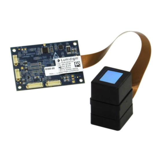
- Page 1 Lumidigm Lumidigm M-Series M3xx Modules Mechanical Integration Guide PLT-02217, Rev. A.0 December 2014 hidglobal.com...
-
Page 2: Table Of Contents
Lumidigm M-Series M3xx Modules Mechanical Integration Guide, PLT-02217, Rev. A.0 Contents Introduction ..........................4 1.1 M-Series Modules Overview ........................4 Human Factor Considerations .................... 5 2.1 Summary of human factor considerations ................... 5 2.2 Human Factor Design Discussion ......................6 Mounting Considerations ..................... - Page 3 HID Global Corporation Trademarks HID GLOBAL, HID, and the HID logo are the trademarks or registered trademarks of HID Global Corporation, or its licensors, in the U.S. and other countries. Lumidigm is a registered trademark of Lumidigm, Inc.
-
Page 4: Introduction
Lumidigm M-Series M3xx Modules Mechanical Integration Guide, PLT-02217, Rev. A.0 Introduction Thank you for your interest in the Lumidigm M-Series M3xx modules. After a brief overview, there are three main sections in this document. First we discuss the human factor considerations that must be taken into account when designing the ergonomics of a successful M-Series module-based product. -
Page 5: Human Factor Considerations
Lumidigm M-Series M3xx Modules Mechanical Integration Guide, PLT-02217, Rev. A.0 2 Human Factor Considerations To achieve the highest biometric performance and the fastest transaction times, the enclosure design incorporating the M3xx module must consider human factors. For a biometric device, it is important to take a design approach that makes finger placement intuitive and naturally guides finger placement to rapidly achieve optimal finger position. -
Page 6: Human Factor Design Discussion
Lumidigm M-Series M3xx Modules Mechanical Integration Guide, PLT-02217, Rev. A.0 • Enclosure materials and ergonomic features should be kept as thin as possible around the platen area to allow easy contact with the platen and avoid the creation of a depression so deep that finger–platen contact is difficult to achieve. •... - Page 7 Lumidigm M-Series M3xx Modules Mechanical Integration Guide, PLT-02217, Rev. A.0 or enforce stable placement so that once a finger is placed, subsequent movement is minimized for about 150ms. • The actual opening in the ergonomic feature that is in contact with the M3xx sensor head should remain rectangular to provide a reliable sealing surface between the ergonomic and the sensor head.
-
Page 8: Mounting Considerations
Lumidigm M-Series M3xx Modules Mechanical Integration Guide, PLT-02217, Rev. A.0 3 Mounting Considerations Presence Detection Illumination System The PD illumination system is directional and the user must approach the sensor from the correct direction, the side opposite of where the flex cable enters the M3xx sensor head. The mechanical design of the enclosure should enforce this approach direction. -
Page 9: Sensor Head
Lumidigm M-Series M3xx Modules Mechanical Integration Guide, PLT-02217, Rev. A.0 Figure 4: PD Figure 5: PD illumination pattern, illumination pattern, side view front view 3.2 Sensor Head The M30x and the M31x product lines use the same sensor head. Figure 6 shows a cutaway view of the M3xx sensor head showing the platen area, enclosure, and an assembly consisting of a PCB with the imager and LEDs and a plastic element that contains lenses for the LEDs and the imager itself. - Page 10 Lumidigm M-Series M3xx Modules Mechanical Integration Guide, PLT-02217, Rev. A.0 The enclosure is constructed from plastic which can be deformed by incorrect or poorly- designed mounting. Thus, while the design itself is resilient, care must be taken while mounting to ensure that pressure is sufficient to seal the platen area but not so excessive that the M3xx sensor head enclosure is deformed.
- Page 11 Lumidigm M-Series M3xx Modules Mechanical Integration Guide, PLT-02217, Rev. A.0 It is strongly suggested that the customer mechanical design be completed in a way such that the capture features used to secure the M3xx sensor head to the enclosure have positive stop features so that the pressure set can be reliably achieved without careful control of retaining screw torque.
- Page 12 M3xx sensor head enclosure and securely grip the mounting features present. Note: M3xx modules do not ship with a mounting clip. 3D CAD models and samples of the clip shown are available from HID Global. Figure 9: Example M3xx sensor head retaining clip...
-
Page 13: Sensor Head Mounting Summary
Lumidigm M-Series M3xx Modules Mechanical Integration Guide, PLT-02217, Rev. A.0 Once the pressure set and compressive properties of the gasket material are determined, the final design consideration is reviewing the overall design for part-to-part tolerances so that when the M3xx is secured to the enclosure, the required minimum gasket pressure is achieved for the loosest part-to-part stack up. -
Page 14: Ecu - M30X
Lumidigm M-Series M3xx Modules Mechanical Integration Guide, PLT-02217, Rev. A.0 3.4 ECU - M30x Note: This section applies to the M30x module ECU only. If you are designing for an M31x module, please refer to the M31x ECU discussion that follows this section. The M30x ECU dimensions are shown in Figure 11. -
Page 15: Connectivity
Lumidigm M-Series M3xx Modules Mechanical Integration Guide, PLT-02217, Rev. A.0 3.4.1 Connectivity Detail for M30x ECU connectivity is provided in Figure 12 and in the chart, both below: Figure 12: M30x ECU connector positions J3, J4, and J7 Connector Position J3 GPIO Mating Hirose connector housing p/n is DF13-7S-1.25C with 26-30AWG crimp terminal p/n DF13-2630SCF. -
Page 16: Ecu - M31X
Lumidigm M-Series M3xx Modules Mechanical Integration Guide, PLT-02217, Rev. A.0 Connector Position J7 RS232 & Alternate Power. Mating Hirose connector housing p/n is DF13-4S-1.25C with 26-28AWG crimp terminal p/n DF13-2630SCF. J7-1 = RS232 RD J7-2 = RS232 TD J7-3 = Ground J7-4 = 5VDC (only if J4-1 is unused) 3.5 ECU - M31x Note: This section applies to the M31x module ECU only. -
Page 17: Connectivity
Lumidigm M-Series M3xx Modules Mechanical Integration Guide, PLT-02217, Rev. A.0 3.5.1 Connectivity Detail for M31x ECU connectivity is provided in Figure 14 and in the chart, both below: Figure 14: M31x ECU connector positions Connector Position MH (USB) White MH3 (USB) Green MH4 (USB) -
Page 18: Gpio Controls
Lumidigm M-Series M3xx Modules Mechanical Integration Guide, PLT-02217, Rev. A.0 3.5.2 GPIO Controls User LEDs can be turned on/off on for M31x products. Sample code follows. “First” corresponds to the MH7 control, “Second” corresponds to the MH9 control. These controls are GPIO ports on a Xilinx part;... -
Page 19: Ecu-To-Sensor Connection
Lumidigm M-Series M3xx Modules Mechanical Integration Guide, PLT-02217, Rev. A.0 3.6 ECU-to-Sensor Connection The M3xx is shipped as three separate components: the ECU, the sensor head, and the connecting flex cable. Care must be taken to assemble the unit correctly to avoid damage to the components. -
Page 20: Environmental Considerations
Lumidigm M-Series M3xx Modules Mechanical Integration Guide, PLT-02217, Rev. A.0 4 Environmental Considerations Previous sections provided mounting approaches that result in an IP65-rated seal where the M3xx platen area meets the external environment. This section provides additional design guidance for engineers responsible for designing an outdoor enclosure containing the M3xx. -
Page 21: Example Outdoor Enclosure
Lumidigm M-Series M3xx Modules Mechanical Integration Guide, PLT-02217, Rev. A.0 4.2 Example Outdoor Enclosure Figure 17 provides an example of an outdoor enclosure design that incorporates design recommendations made in this document. The sensor platen area is shielded from direct exposure to sunlight when the enclosure is mounted on a vertical wall. -
Page 22: M3Xx Specifications
Lumidigm M-Series M3xx Modules Mechanical Integration Guide, PLT-02217, Rev. A.0 4.3.2 M3xx Specifications Operating temperature internal 0C to 60°C Operating humidity internal 0 to 95% RH non condensing Maximum background light intensity 18Klux Platen seal rating IP65 Unit seal rating None - open to environment Electronics conformal coating None... - Page 23 Lumidigm M-Series M3xx Modules Mechanical Integration Guide, PLT-02217, Rev. A.0 If the enclosure’s control surfaces are shaded but the unit itself is placed in direct sunlight the interior temperature of the enclosure will approach the external temperature + the solar gain.
-
Page 24: Water And Dust Sealing Considerations
Lumidigm M-Series M3xx Modules Mechanical Integration Guide, PLT-02217, Rev. A.0 4.5 Water and Dust Sealing Considerations IP enclosure ratings indicate the level of protection the enclosure has against ingress of solids and water into the enclosure. Ratings are displayed in the format “IPxy”, where: x - indicates the level of protection that the enclosure provides against ingress of solid foreign objects 5 - dust protected... -
Page 25: Background Light Considerations
Lumidigm M-Series M3xx Modules Mechanical Integration Guide, PLT-02217, Rev. A.0 4.6 Background Light Considerations The M3xx imaging system uses a direct imaging path, similar to that of a camera, to take pictures of the finger. It transforms these pictures into a contrast-enhanced grayscale fingerprint image. -
Page 26: Condensation Considerations
Lumidigm M-Series M3xx Modules Mechanical Integration Guide, PLT-02217, Rev. A.0 4.7 Condensation Considerations Any enclosure with an interior air mass containing water vapor must provide controls to prevent or manage condensation. Condensation will form on any surface with a temperature at or below the dew point of the air mass. The dew point temperature is a function of the absolute amount of water present in the air mass and the air mass temperature. -
Page 27: Conclusion
Lumidigm M-Series M3xx Modules Mechanical Integration Guide, PLT-02217, Rev. A.0 This not only helps make sure the interior platen temperature is warmer than the enclosure air mass, but it also addresses the human comfort issues mentioned in the earlier discussion on temperature control. - Page 28 hidglobal.com...
Need help?
Do you have a question about the Lumidigm M Series and is the answer not in the manual?
Questions and answers