Advertisement
Output Control Module
Supplied parts
◾ HID Aero X300 Ouput Control Module (1)
◾ Installation guide (1)
◾ Mounting screws (4) 0.138" × 1" (3.5 mm × 25 mm)
Recommended parts
(not supplied)
◾ Certified DC power supply
◾ Drill with various bits for mounting hardware
◾ For DIN rail mounting: Brackets (2) - Phoenix Contact,
USA 10 Series Rail Adapter, part number 1201578.
Screws (4) - Self tapping, countersunk,
3.0 mm × 10 mm (or 3.0 mm × 8 mm)
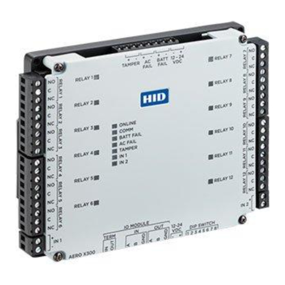
X300 Overview
The X300 has 12 relays, five inputs and one RS-485 port for IO module connection.
See page 6
RELAYS 1-12
See step 4.
"
4.53
(115 mm)
INPUTS 1-2
See step 3.
JUMPERS
See step 2.
INSTALLATION GUIDE
CABLE REQUIREMENTS (NOT SUPPLIED)
IO Module
Alarm Inputs
Relay Outputs As required for the load
Power
POWER, TAMPER, AC FAIL, BATT FAIL
See step 6.
"
5.51
(140 mm)
PLT-04236, Rev. A.3
One twisted pair, shielded, 24 AWG, 120
impedance, 4,000 ft (1,200 m) maximum
One twisted pair, 30 maximum
2-conductor shielded
18 to 16 AWG, 500 ft (150 m)
Status LEDs
See page 6
RELAYS 1-12
See step 4.
INPUTS 1-2
See step 3.
DIP SWITCH
See step 5.
IO MODULE PORT
See step 2.
Advertisement
Table of Contents

Related Manuals for HID Aero X300


Summary of Contents for HID Aero X300
- Page 1 INSTALLATION GUIDE Output Control Module PLT-04236, Rev. A.3 Supplied parts CABLE REQUIREMENTS (NOT SUPPLIED) ◾ HID Aero X300 Ouput Control Module (1) One twisted pair, shielded, 24 AWG, 120 IO Module ◾ Installation guide (1) impedance, 4,000 ft (1,200 m) maximum ◾...
- Page 2 HID Aero™ X300 Installation Guide Mounting the X300 ATTENTION Observe precautions for handling ELECTROSTATIC SENSITIVE DEVICES ◾ Always mount the controllers and interface panels in a secure area. ◾ Mount using the supplied screws 0.138" × 1" (3.5 mm × 25 mm).
- Page 3 HID Aero™ X300 Installation Guide Input circuit wiring Inputs are typically used for the following: Unsupervised circuit IN 1 or IN 2 ◾ To monitor door position. ◾ Request to exit. ◾ Alarm contacts. Input IN 1 and IN 2 circuits can be configured as unsupervised or supervised and can use normally open or normally closed contacts.
- Page 4 HID Aero™ X300 Installation Guide DIP switch configuration Switches 1 through 5 select the device address. Switches 6 and 7 select the communication baud rate. Switch 8 is not in use. SELECTION Address 0 Address 1 Address 2 Address 3...
- Page 5 HID Aero™ X300 Installation Guide Input power, cabinet tamper, and UPS fault input wiring The X300 requires 12-24 V DC power. Connect power with minimum of 18 AWG wire. Connect power ground to earth ground in only ONE LOCATION within the system. Multiple earth ground connections may cause ground loop problems and is not advised.
- Page 6 HID Aero™ X300 Installation Guide Status LEDs POWER NORMAL OPERATION ON SELF-TEST Heartbeat and Online status. Offline = 1 sec rate, 20% ON. Online encrypted comm .1 sec ONLINE ON then OFF ON, .1 sec OFF, .1 sec ON, .1 sec OFF, .1 sec ON, .1 sec OFF, .1 sec ON, .3 sec OFF. Waiting for application download .1 sec ON, .1 sec OFF.
- Page 7 HID Aero™ X300 Installation Guide Specifications HID AERO X300 Input Voltage 12 to 24 V DC ± 10% Maximum Input Current 500 mA 2-wire RS-485, 2,400 to 115,200 bps, asynchronous, IO Module half-duplex, 1 start bit, 8 data bits, and 1 stop bit Five unsupervised/supervised, standard EOL: 1k/1k, 1%, ¼...
Need help?
Do you have a question about the Aero X300 and is the answer not in the manual?
Questions and answers