
Related Manuals for HID ADC-AC-X300


Summary of Contents for HID ADC-AC-X300
- Page 1 X300 Output Control Expansion Module Installation Guide Only compatible with HID Aero Series ADC-AC-X300 controllers...
- Page 2 Have you taken the Smarter Access Control Already familiar with Smarter Access Control? Great! You can take training course yet? the Fast Track training assessment to complete the training requirement. All training can be found here: https://academy.alarm.com/series/ This course is recommended for every installer and is required for three access-control or by scanning the reps per Service Provider before Access Control hardware can be added to QR code above in MobileTech.
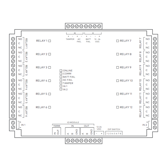
- Page 3 X300 Output Control Expansion Module The ADC-AC-X300 expansion module provides a TAMPER BATT 12 - 24 RELAY 1 RELAY 7 FAIL FAIL solution for controlling twelve additional outputs. Three dedicated inputs are provided for Tamper, RELAY 2 RELAY 8 AC Fail, and Battery Fail. Two inputs are provided...
- Page 4 Wiring Connections TB1-1 TB2-4 TB4-4 Relay 8 Normally Open Contact TB5-7 Relay 12 Normally Open Contact Relay 5 Normally Open Contact Relay 1 Normally Open Contact TB2-5 RELAY 5 TB4-5 RELAY 8 Relay 8 Common Contact TB5-8 RELAY 12 Relay 12 Common Contact TB1-2 RELAY 1 Relay 5 Common Contact...
-
Page 5: Status Leds
Status LEDs TB7-7 Input Power Ground LED Label Represents Initialization Normal Operation OFF = Inactive, RELAY 4 ON = Energized AC FAIL ON then OFF ON = Active, 12-24 VDC Input Power Ground Heartbeat and RELAY 5 ON = Energized Flash = Fault* TB7-8 (from local power) -
Page 6: Communication Wiring
(minimum 24 AWG) with drain wire and shield for X300 X300 communication. If the ADC-AC-X300 is the last device on ∙ If there are additional downstream expansion the communication bus, jumper J1 must be set to “IN”. modules, set jumper to “OUT”... -
Page 7: Relay Wiring
To minimize premature contact failure and to increase system reliability, a contact protection circuit may be Flip the DIP switches on the the ADC-AC-X300 expansion Twelve Form-C contact relays are provided for controlling used. The following circuit is recommended. Locate module according to the “Jumpers/Switches ON”... -
Page 8: Diode Selection
Diode Selection Specifications Certifications The input circuit wiring configurations shown are UL 294 and UL1076 recognized supported but may not be typical. ∙ The interface is for use in low voltage, Class 2 CE compliant Diode current rating: 1x strike current circuits only. - Page 9 Warranty Alarm.com warrants the product is free from defects in material and workmanship This device complies with part 15 of the FCC Rules. Operation is subject under normal use and service with proper maintenance for one year from the date to the following two conditions: of factory shipment.
- Page 10 Notes Notes...
- Page 11 8281 Greensboro Drive Suite 100 210406 Tysons, VA 22102 © 2021 Alarm.com. All rights reserved. Designed in the USA. Made in USA.
Need help?
Do you have a question about the ADC-AC-X300 and is the answer not in the manual?
Questions and answers