
Related Manuals for HID iCLASS SE


Summary of Contents for HID iCLASS SE
- Page 1 SE Reader Module Hardware Developer’s Guide SE3200-902, Rev. C.1 February 2014 h i d g l o b a l . c o m...
-
Page 2: Table Of Contents
SE Reader Module Hardware Developer’s Guide, SE3200-902, Rev. C.1 Contents Introduction ........................... 7 Product Description ............................7 1.1.1 Key Features ................................. 7 1.1.2 iCLASS SE Reader Module Products ......................... 8 1.1.3 Product Guide ................................9 Scope/Purpose ............................... 9 Terms and Abbreviations .......................... 10 Overview .......................... - Page 3 SE Reader Module Hardware Developer’s Guide, SE3200-902, Rev. C.1 RF Interfaces ........................27 HF Interface (13.56 MHz) .......................... 27 6.1.1 Ultra Low Power Mode ............................29 Prox Interface (125 kHz; SE32x0APx only) ..................30 Antennas..........................31 Basic Antenna Operation .......................... 31 7.1.1...
- Page 4 Basic Antenna Tuning Network ........................... 28 Figure 10: Tuning Network with ULPM Support ........................ 29 Figure 11: iCLASS SE Reader Module Prox Interface with Antenna ................. 30 Figure 12: Inductive Coupling Principle ..........................32 Figure 13: Mutual Inductance between Reader and Transponder Antenna ............32 Figure 14: Load Modulation Principle .............................
- Page 5 Table 23: Power Considerations .............................. 39 Table 24: 4090A11 HF Antenna with Standard ID1 Transponders Read Ranges ..........40 Table 25: Typical Read Ranges 4090A11 HF Antenna - HID Multi Technology Cards ........42 Table 26: ULPM Card Detection Ranges 4090A10 HF Antenna ................43 Table 27: ISO/IEC14443 Type A Modulation Waveforms ....................
- Page 6 HID Global Corporation. Trademarks HID GLOBAL, HID, the HID logo, iCLASS, iCLASS SE, and SIO are the trademarks or registered trademarks of HID Global Corporation, or its licensors, in the U.S. and other countries.
-
Page 7: Introduction
Approved Products List (APL) allowing straightforward integration into U.S. Government applications. The iCLASS SE Reader’s dual frequency capability allows the use of both high and low frequency credentials with the same reader, providing a solution for mixed credential and credential migration applications. -
Page 8: Iclass Se Reader Module Products
SE Reader Module Hardware Developer’s Guide, SE3200-902, Rev. C.1 · FIPS 201 PIV II compliance with inclusion on the GSA APL · Ultra low power mode for battery- operated devices · EAL5+ certified secure element hardware for protection of keys and cryptographic operations to guard against security threats 1.1.2... -
Page 9: Product Guide
1.1.3 Product Guide The iCLASS SE reader module comes in two form factors. It can also be configured for high frequency card reading only or High & low frequency (prox). In addition, there are two different levels of security provided. -
Page 10: Terms And Abbreviations
SE Reader Module Hardware Developer’s Guide, SE3200-902, Rev. C.1 Terms and Abbreviations Abbreviation/Term Description Antenna Advanced RISK Machine Card Serial Number Do Not Connect Electro Magnetic Compatibility Frequency Shift Keying Federal Communication Commission High Frequency (13.56 MHz) Light Emitting Diode... -
Page 11: Overview
SE Reader Module Hardware Developer’s Guide, SE3200-902, Rev. C.1 2 Overview Features Table 1: Feature Overview Type Feature Comment ISO/IEC14443 Type A&B up to 848kbps, ISO/IEC14443 MIFARE Classic, MIFARE DESFire 0.6 & EV1 ISO/IEC15693 CSN only Pico15693 ISO/IEC15693 with proprietary protocol... -
Page 12: Block Diagram
SE Reader Module Hardware Developer’s Guide, SE3200-902, Rev. C.1 2.2 Block Diagram Figure 1: iCLASS SE Reader Module Block Diagram February 2014 Page 12 of 52... -
Page 13: Theory Of Operation
Note: If developing a handheld unit, operate the iCLASS SE Reader Module in Normal Power Mode and disable the power when not in use. -
Page 14: Peripheral Circuits
· The OEM50 connector is a 2 X 6 0.1" space pin header or PWB hole pattern. · The OEM50 has a two-wire interface to the antenna and the iCLASS SE Reader has a 2-wire interface for NPM and a 5-wire interface for ULPM applications. -
Page 15: Oem75
SE Reader Module Hardware Developer’s Guide, SE3200-902, Rev. C.1 OEM50 SE32XX Pin 1 Open Output SE32XX does not have a similar signal Pin 2 Ground Same as P301 pin 2, signal Ground Wiegand data output is per the SIA AC-01 (1996.10) specification, except Voh is 3.3VDC max, and not 4.0 to... -
Page 16: Connector Configuration
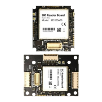
SE Reader Module Hardware Developer’s Guide, SE3200-902, Rev. C.1 3 Connector Configuration SE3200Axx Connectors Figure 2: SE3200Axx Connector Configuration 3.2 SE3210Axx Connectors Figure 3: SE3210Axx Connector Configuration February 2014 Page 16 of 52... -
Page 17: Pin Configuration
SE Reader Module Hardware Developer’s Guide, SE3200-902, Rev. C.1 3.3 Pin Configuration 3.3.1 P301 Host Interface Connector This connector is compatible with P1 of the OEM75 module. Table 2: P301 Pin Configuration Signal Name Type Function +3.3 VDC Output 0.1W maximum power sourced output... -
Page 18: P702 Board To Board Connector
SE Reader Module Hardware Developer’s Guide, SE3200-902, Rev. C.1 3.3.3 P702 Board to Board Connector This connector is an alternative interconnection method to P301 and P701. Table 4: P702 Pin Configuration Signal Name Type Function Signal that holds off the presentation of the card data. -
Page 19: P401 Hf Antenna Connector
SE Reader Module Hardware Developer’s Guide, SE3200-902, Rev. C.1 3.3.4 P401 HF Antenna Connector This antenna connection IS NOT compatible with an OEM75 antenna. Table 5: P401 Pin Configuration Signal Name Type Function Output 13.56 MHz antenna driving signal... -
Page 20: Mechanical Specifications
SE Reader Module Hardware Developer’s Guide, SE3200-902, Rev. C.1 4 Mechanical Specifications The following section details the mechanical specifications for the iCLASS SE Reader Module and its connectors. Detailed drawings are also available at the iCLASS SE Reader Module micro-site. SE3200Axx This form factor is compatible with OEM75 model 3141ADx. -
Page 21: Se3210Axx
SE Reader Module Hardware Developer’s Guide, SE3200-902, Rev. C.1 4.2 SE3210Axx This form factor is compatible with OEM75 modules 3141AAx, 3141AEx and 3141ACx. Figure 5: SE3210Axx Mechanical Drawing Page 21 of 52 February 2014... -
Page 22: Connector Types
SE Reader Module Hardware Developer’s Guide, SE3200-902, Rev. C.1 4.3 Connector Types 4.3.1 SE3210Axx Connector Types The following connectors are used for interconnection with host and antenna. Table 7: SE3210 Connector Types Connector Function Type / Counterpart Manufacturer: Molex... -
Page 23: Electrical Specifications
5.2 Current Draw The following measurements were performed with a 50 Ohm load connected to the HF interface. In the case a real antenna is connected to the iCLASS SE Reader Module’s power, consumption changes depending on the presence of a transponder and its relative position to the antenna. -
Page 24: Power Supply
SE Reader Module Hardware Developer’s Guide, SE3200-902, Rev. C.1 5.3 Power Supply Table 10: Power Supply Electrical Characteristics Signal Parameter Unit Input Voltage SE32x0A0x 10.00 Input Voltage SE32x0APx 10.00 Current Consumption Normal Operation Current Consumption Ultra Low Power Mode µA... -
Page 25: Regulated Voltage Outputs
SE Reader Module Hardware Developer’s Guide, SE3200-902, Rev. C.1 Table 12: Wiegand Electrical Characteristics – Host Interface Signal Parameter Unit WG_DATA0 Current Draw (into 1K + 10ohms) 2.6(*) WG_DATA1 WG_DATA0 High Level Output Voltage WG_DATA1 5.6 I/O The I/O signals are backward compatible to the OEM75 product. -
Page 26: Rf Interface (125 Khz/Prox)
SE Reader Module Hardware Developer’s Guide, SE3200-902, Rev. C.1 5.9 RF Interface (125 kHz/Prox) Table 16: 125 kHz RF Interface - Electrical Characteristics Power Supply Signal Parameter Unit PROX_TX1 Output Peak Current PROX_TX2 5.10 Start Up Voltages Although power supply rise time is not critical for the module, the best way to control the module at start up is by actively controlling the reset line. -
Page 27: Rf Interfaces
SE Reader Module Hardware Developer’s Guide, SE3200-902, Rev. C.1 6 RF Interfaces Depending on the configuration, the iCLASS SE Reader Module offers up to two different RF interfaces. · HF interface for 13.56 MHz transponders · Prox interface for 125 kHz transponders (SE32x0APx only) HF Interface (13.56 MHz) -
Page 28: Figure 9: Basic Antenna Tuning Network
In practice, Cs and Cp may consist of several parallel capacitors to get better granularity. Be aware that HID is offering further documents, support and services in terms of antenna design and support. These might require special or service level agreements. -
Page 29: Ultra Low Power Mode
SE Reader Module Hardware Developer’s Guide, SE3200-902, Rev. C.1 6.1.1 Ultra Low Power Mode To allow for the ULPM, take additional measures at the antenna circuit. A transistor, as well as two additional measurement lines, is introduced to enable the low power card detection circuit on the iCLASS SE Reader Module. -
Page 30: Prox Interface (125 Khz; Se32X0Apx Only)
SE Reader Module Hardware Developer’s Guide, SE3200-902, Rev. C.1 6.2 Prox Interface (125 kHz; SE32x0APx only) The Prox interface is optimized for connection to the HID Prox antenna 6500-101-03. If this antenna or one with equal electrical characteristics is used, no additional components are required. -
Page 31: Antennas
SE Reader Module Hardware Developer’s Guide, SE3200-902, Rev. C.1 7 Antennas All antennas offered for the iCLASS SE Reader Module are optimized for a free air environment. A free air environment is one in which there are no external effects on the field produced by the antenna and which might degrade its performance (for example, metal or stray capacitance). -
Page 32: Inductive Coupling
SE Reader Module Hardware Developer’s Guide, SE3200-902, Rev. C.1 7.1.1 Inductive Coupling An inductively coupled transponder usually consists of a single chip and an attached coil, which is used as an antenna. Most inductively coupled transponders are passive, meaning that power is supplied by the reader. -
Page 33: Load Modulation
SE Reader Module Hardware Developer’s Guide, SE3200-902, Rev. C.1 7.1.2 Load Modulation As previously mentioned, interpret the inductively coupled system as a transformer. Putting a transponder (with a SRF around 13.56 MHz) into the magnetic field of a reader absorbs energy from the field. This loading of the reader’s antenna, caused by the transponder, is represented as transformed impedance at the antenna. -
Page 34: 4090A10 Hf Antenna
SE Reader Module Hardware Developer’s Guide, SE3200-902, Rev. C.1 design services through a Customer Product Opportunity Program. 7.3 4090A10 HF Antenna Figure 15: 4090A10 HF Antenna The 4090A10 HF antenna has an impedance of 50W and is optimized for operation with a 50mm ribbon cable. - Page 35 SE Reader Module Hardware Developer’s Guide, SE3200-902, Rev. C.1 Transponder / Standard / Form Typical Read Manufacturer Factor Range [mm] IC Type Modulation Scheme [MHz] (SLE66CL160S) Technologies (Type A) 15.34 MIFARE Plus™ X ISO/IEC14443 ID1 Card 15.58 (MF1PLUSx0) Semiconductors (Type A) 14.94...
-
Page 36: Typical Read Ranges With Hid Multi Technology Cards
ULPM Card Detection Range The card detection range in Ultra Low Power Mode depends on the loading effect the transponder imposes on the iCLASS SE Reader Module’s antenna. That means that cards with lower loading effect will generally have a shorter detection range. -
Page 37: Rf Properties
RF Properties Provided is an overview on the RF properties of the 4090A10 HF antenna in combination with the iCLASS SE Reader Module. The modulation waveforms were measured at a distance of 10mm. Parameters may vary per unit due to component tolerances. -
Page 38: Table 20: Iso/Iec14443 Type A Modulation Waveforms
SE Reader Module Hardware Developer’s Guide, SE3200-902, Rev. C.1 Table 20: ISO/IEC14443 Type A Modulation Waveforms 2.52µs Pause Length 520ns Low Time 325ns Rise Time to 98ns Rise Time to Overshoot 8.53% Table 21: ISO/IEC14443 Type B Modulation Waveforms... -
Page 39: Power Considerations
SE Reader Module Hardware Developer’s Guide, SE3200-902, Rev. C.1 Table 22: FeliCa Waveforms 730ns Rise Time 610ns Fall Time Modulation 12.50% Index Overshoot 0.2 % Undershoot 0.1% 7.3.6 Power Considerations If a transponder is presented to the 4090A10 HF antenna, the impedance of the antenna is bound to change. -
Page 40: 4090A11 Hf Antenna
SE Reader Module Hardware Developer’s Guide, SE3200-902, Rev. C.1 7.4 4090A11 HF Antenna Figure 16: 4090A11 HF Antenna The 4090A11 HF antenna has an impedance of 50W and is optimized for operation with a 50mm ribbon cable. The antenna is tuned for a free air environment. - Page 41 SE Reader Module Hardware Developer’s Guide, SE3200-902, Rev. C.1 Typical Transponder / Standard / Manufacturer Form Factor Read Range IC Type Modulation Scheme [MHz] [mm] 14.51 MIFARE Ultralight ISO/IEC14443 (Type ID1 Card 14.64 (MF0ICU1) Semiconductors 15.17 MIFARE Ultralight ISO/IEC14443 (Type ID1 Card 14.12...
-
Page 42: Typical Read Ranges With Hid Multi Technology Cards
For Prox read ranges, see Section 7.5 6500-101-03 Prox Antenna. Note: Read range varies depending on the transponders antenna size, design, SRF and Quality. Table 25: Typical Read Ranges 4090A11 HF Antenna - HID Multi Technology Cards Card Type Manufacturer... -
Page 43: Ulpm Card Detection Range
ULPM Card Detection Range The card detection range in Ultra Low Power Mode depends on the loading effect the transponder imposes on the iCLASS SE Reader Module’s antenna. That means that cards with lower loading effect will generally have a shorter detection range. -
Page 44: Table 27: Iso/Iec14443 Type A Modulation Waveforms
SE Reader Module Hardware Developer’s Guide, SE3200-902, Rev. C.1 4090A10 Magnetic Field Strength H d[mm] Table 27: ISO/IEC14443 Type A Modulation Waveforms 2.39µs Pause Length 1.48µs Low Time 551ns Rise Time to 90% 198ns Rise Time to 60% Overshoot 1.03%... -
Page 45: Table 28: Iso/Iec14443 Type B Modulation Waveforms
SE Reader Module Hardware Developer’s Guide, SE3200-902, Rev. C.1 Table 28: ISO/IEC14443 Type B Modulation Waveforms 510ns Rise Time 267ns Fall Time Modulation Index 13.15% Overshoot 3.77% Undershoot 6.90% Table 29: FeliCa Waveforms 320ns Rise Time 480ns Fall Time Modulation Index 12.23%... -
Page 46: 45 7.4.7 Power Considerations
70mm distance Note: The measurements were taken with constant carrier on. 7.5 6500-101-03 Prox Antenna The iCLASS SE Reader Module is optimized for operation with this Prox antenna. No external components are required. Figure 17: 6500-101-03 Prox Antenna February 2014... -
Page 47: Mechanical Data
Detailed drawings are available at the iCLASS SE Reader Module micro-site. The antenna has two 76.2mm 28AWG mag wire leads for interconnection to the iCLASS SE Reader Module. For soldering, a strip end with 3.81mm is included. Figure 18: 6500-101-03 Mechanical Drawing 7.5.2... -
Page 48: Typical Read Ranges
SE Reader Module Hardware Developer’s Guide, SE3200-902, Rev. C.1 7.5.3 Typical Read Ranges The measured read ranges are indications only. Read range varies due to transponder antenna size and quality, as well as environmental effects. Table 32: Typical Read Ranges 6500-101-03 Prox Antenna... -
Page 49: Regulatory
· Transient surge protection (transorbs) is not provided for the SE32XX module. · The iCLASS SE Reader module is intended to be part of a reader. The reader in which the iCLASS SE Reader module is used must translate the 3 VDC module Voh signaling to 4 to 5.5 VDC Voh SIA AC-01 (1996.10) signaling requirements. -
Page 50: Fcc
SE Reader Module Hardware Developer’s Guide, SE3200-902, Rev. C.1 · Obtain FCC Certification by submitting the final product to a Telecommunications Certified Body (TCB) laboratory that performs the testing and issue the FCC Grant. Standard: Part 15, Subpart C. -
Page 51: Ce Marking
HID Global bestätigt hiermit, dass die Leser die wesentlichen Anforderungen und anderen relevanten Bestimmungen der Richtlinie 1999/5/EG erfüllen and 2006/95/EC. HID Global dichiara che i lettori di prossimità sono conformi ai requisiti essenziali e ad altre misure rilevanti come previsto dalla Direttiva europea 1999/5/EC and 2006/95/EC. - Page 52 HID Global Headquarters: North America: +1 949 732 2000 Toll Free: 1 800 237 7769 Europe, Middle East, Africa: +49 6123 791 0 Asia Pacific: +852 3160 9800 Latin America: +52 477 779 1492 support.hidglobal.com hidglobal.com...
Need help?
Do you have a question about the iCLASS SE and is the answer not in the manual?
Questions and answers