Table of Contents
Troubleshooting

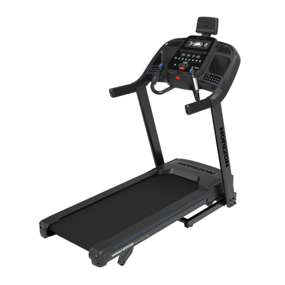
Related Manuals for Johnson Horizon Fitness 7.0AT-04


Summary of Contents for Johnson Horizon Fitness 7.0AT-04
- Page 1 Issue Date 22/11/2021 Edition Doc No. JOHNSON Revision Date Prepared by Claire Nguyen Page JOHNSON HEALTH INDUSTRY (VIETNAM) CO., LTD. 7.0AT-04 SERVICE MANUAL Approved by Reviewed by Prepared by Claire Nguyen...
- Page 2 PRODUCT BROWSER...
- Page 3 PRODUCT BROWSER...
-
Page 4: Table Of Contents
CONTENTS CHAPTER 1: SERIAL NUMBER INFORMATION ....................6 1. 1 SERIAL NUMBER LOCATION ....................... 6 1.2 MODEL APPLY LIST (for reference) ..................... 7 CHAPTER 2: PREVENTATIVE MAINTENANCE ....................8 2.1 PREVENTATIVE MAINTENANCE......................8 2.1.1 EVERY DAY (DAILY) ........................... 8 2.1.2 EVERY WEEK (WEEKLY) ........................8 2.1.3 EVERY MONTH –... - Page 5 CHAPTER 3: CONSOLE INSTRUCTION CHAPTER 6: PART REPLACEMENT GUIDE ....................39 6.1 MOTOR REPLACEMENT ........................39 6.2 REAR ROLLER REPLACEMENT ......................40 6.3 SIDE RAIL REPLACEMENT ........................41 6.4 RUNNING DECK REPLACEMENT ......................42 6.5 FRONT ROLLER REPLACEMENT ......................43 6.6 RUNNING BELT REPLACEMENT ......................
-
Page 6: Chapter 1: Serial Number Information
CHAPTER 1: SERIAL NUMBER INFORMATION CHAPTER 1: SERIAL NUMBER INFORMATION 1. 1 SERIAL NUMBER LOCATION (For example) -
Page 7: Model Apply List (For Reference)
CHAPTER 1: SERIAL NUMBER INFORMATION 1.2 MODEL APPLY LIST (for reference) ENTER YOUR SERIAL NUMBER AND MODEL NAME IN THE BOXES BELOW: Refer to the SERIAL NUMBER and MODEL NAME when calling for service. -
Page 8: Chapter 2: Preventative Maintenance
CHAPTER 2: PREVENTATIVE MAINTENANCE CHAPTER 2: PREVENTATIVE MAINTENANCE 2.1 PREVENTATIVE MAINTENANCE Preventative maintenance is the key to smoothly operating equipment, as well as keeping the user’s liability to a minimum. Equipment needs to be inspected at regular intervals. Defective components must be replaced immediately. -
Page 9: Tensioning & Centering The Running Belt
CHAPTER 2: PREVENTATIVE MAINTENANCE Your treadmill came with a bottle of lubricant which can be used for two applications. Turn off the treadmill with the on/off switch, then unplug the power cord at the wall outlet. Loosen both the rear roller bolts. (For best results, place two removable marks on both sides of the frame and note roller position). - Page 10 CHAPTER 2: PREVENTATIVE MAINTENANCE If the running belt is too far to the right side: With the treadmill running at 1 mph, turn the left adjustment bolt counter-clockwise ¼ turn at a time (using the supplied Allen wrench). Check the belt alignment. Allow belt to run a full cycle to gauge if more adjustment is needed.
-
Page 11: Chapter 3: Console Instruction
CHAPTER 3: CONSOLE INSTRUCTION CHAPTER 3: CONSOLE INSTRUCTION 3.1 CONSOLE OPERATION Note: There is a thin protective sheet of clear plastic on the overlay of the console that should be removed before use. A) LCD DISPLAY WINDOW: Calories, Place, Total time, Heart Rate, Incline, Speed B) LED DISPLAY: Segment Time, Incline, Speed, Distance, Total Time, Calories, Pace, Heart Rate. -
Page 12: Display Windows
CHAPTER 3: CONSOLE INSTRUCTION L) FAN: personal workout fan. M) SPEAKERS: music plays through speakers when your CD / MP3 player is connected to the console. N) AUDIO IN JACK: plug your CD / MP3 player into the console using the included audio adaptor cable. -
Page 13: Getting Started
CHAPTER 3: CONSOLE INSTRUCTION 3.3 GETTING STARTED 1) Check to make sure no objects are placed on the belt that will hinder the movement of the treadmill. 2) Plug in the power cord and turn the treadmill ON. (The ON/OFF switch is next to the power cord.) 3) Stand on the side rails of the treadmill. - Page 14 CHAPTER 3: CONSOLE INSTRUCTION To program the INTERVAL button, you must select a user, start the machine, set the desired speed and incline, press and hold the desired INTERVAL button for three seconds until the treadmill beeps. Now the INTERVAL button is programmed to your settings. After programming the INTERVAL button, it will remember the setting for that user until reprogrammed.
- Page 15 CHAPTER 3: CONSOLE INSTRUCTION BLUETOOTH HEART RATE MONITORING The 7.0AT is equipped with multi-channel Bluetooth which enables you to wirelessly connect compatible Bluetooth heart rate monitoring devices to this treadmill. You will need to ensure that your wireless heart rate monitoring device is Bluetooth 4.0 compatible and is also “open” to sharing data. Non-“open” or “closed”...
- Page 16 CHAPTER 3: CONSOLE INSTRUCTION WHEN UNIT IS POWERED OFF THEN BACK ON If you turn your treadmill or elliptical unit off, or if it goes into sleep mode, the next time it is powered on the unit will look to pair with the last music device with which it was paired. It will automatically pair at this time.
-
Page 17: Program Information
CHAPTER 3: CONSOLE INSTRUCTION 3.4 PROGRAM INFORMATION 1) MANUAL: Control everything about your workout – from start to finish. This program is a basic workout with no pre-defined settings, allowing you to manually adjust the machine at any time. It begins with an incline at 0 and speed at 0.5 mph. - Page 18 CHAPTER 3: CONSOLE INSTRUCTION 5) HILL CLIMB: Simulates a hill ascent and descent. This program helps tone muscle and improve cardiovascular ability. Incline changes and segments repeat every 30 seconds. 6) TARGET HEART RATE: This program is designed for you to improve your overall cardiovascular fitness levels.
- Page 19 CHAPTER 3: CONSOLE INSTRUCTION 7) MY FIRST 5K: This 9-week program is intended for inexperienced runners looking to run their first 5k or simply begin an exercise routine. It is designed specifically to keep you motivated and engaged, gradually building your strength, increasing your stamina and giving you the confidence it takes to complete your first 5k.
-
Page 20: Chapter 4: Engineering Mode
CHAPTER 4: ENGINEERING MODE CHAPTER 4: ENGINEERING MODE 4.1 ENGINEERING MODE To enter Engineering Mode, press and hold the in cline quick key 15 and speed quick key 12 for 3 to 5 seconds. Function Sub Function Operation Display show as Press incline 15 and speed Ready 12 at the same time for 3... - Page 21 CHAPTER 4: ENGINEERING MODE Clockwise rotate “push to No defined select” to enter Not function function Press “stop” 3 seconds to escape present function Clockwise rotate “push to Ready select” to enter ENG3 Energy save Press “push to select” to enter Switch function...
- Page 22 CHAPTER 4: ENGINEERING MODE Press “push to select” to MCB version enter Escape Escape present Press “stop” 3 seconds function...
-
Page 23: Engineering Mode Overview
CHAPTER 4: ENGINEERING MODE 4.2 ENGINEERING MODE OVERVIEW... - Page 24 CHAPTER 4: ENGINEERING MODE...
-
Page 25: Chapter 5: Troubleshooting
CHAPTER 5: TROUBLESHOOTING CHAPTER 5: TROUBLESHOOTING 5.1 WIRING SCHEMATIC 7.0AT-04 CONSOLE WIRE CONNECTION SCHEMATIC V1.0... - Page 26 CHAPTER 3: CONSOLE INSTRUCTION...
-
Page 27: Mcb Wiring Instructions
CHAPTER 5: TROUBLESHOOTING 5.2 MCB WIRING INSTRUCTIONS Power Line Incline motor power cable Speed sensor cable Console set cable Software burning cable Drive motor cable MCB LED Configuration... - Page 28 CHAPTER 5: TROUBLESHOOTING Table 1 LED No Color Active Inactive Function Symptom Light on Light off Drive Motor active No voltage to drive motor LED1 Green flash -------- MCU status see Table 2 See table 2 Table 2 LED Flash Status Action Condition Failure Parts...
- Page 29 CHAPTER 5: TROUBLESHOOTING Console Circuit Board Instruction: To LCD display J1IC From hear rate grip (left) J2IC From hear rate grip (right) J2KB From Quick key Left hand bar J3KB From Quick key Right hand bar J1IA To MCB J5AA To Audio In &...
-
Page 30: Troubleshooting Summary
CHAPTER 5: TROUBLESHOOTING 5.3 TROUBLESHOOTING SUMMARY Code Description Symptom Solution NO POWER TO THE Turn on the power switch, but the See section 5.4 CONSOLE console will no light up The safety key inserted in console, but NO FUNCTIN FOR SAFETY display window still shows “safety key See section 5.5 off”... -
Page 31: Power To The Console
CHAPTER 5: TROUBLESHOOTING 5.4 NO POWER TO THE CONSOLE Preliminary Solution: A. Check circuit breaker, reset if necessary.(Fig-1) B. Check if the outlet is well. - If no, please try another functional outlet. C. Check if the power cord connected well. - If the power cord connected well but console doesn’t turn on, try another one. -
Page 32: Function For Safety Key
CHAPTER 5: TROUBLESHOOTING 5.5 NO FUNCTION FOR SAFETY KEY SOLUTION: A. Check if the safety key is totally inserted into the console. - If not, remove and insert again. B. Check if the safety key is oxidized or its condition does not affect its function. - If yes, try cleaning it or replace it. -
Page 33: Response For Machine (Console & Motor)
CHAPTER 5: TROUBLESHOOTING 5.6 NO RESPONSE FOR MACHINE (CONSOLE & MOTOR) SOLUTION: A. Check if the console beeps when all keys are pressed. If no, replace the keypads. B. Enter Engineering Mode, and scroll to ENG 1 (Hardware Test).Press the key “ENTER” first and then the key ”START”. -
Page 34: Incline Motor Issues
CHAPTER 5: TROUBLESHOOTING 5.7 INCLINE MOTOR ISSUES: SOLUTION: A. Press the "INCLINE" keys, the console should beep and display incline change, if no, replace the key pad. B. Enter Engineering Mode, and scroll to ENG 1 (Hardware Test). Press the “push to select” key first and then the “START”... -
Page 35: Noise Issues
CHAPTER 5: TROUBLESHOOTING 5.8 NOISE ISSUES SOLUTION: A. Humping noise twice per rotation on new machine. Solution: This noise is from the roller or running belt. -If this is a new unit, some noise is normal as the running belt forms around the rollers. -Check that the belt is centered and tensioned correctly. -
Page 36: Speaker / Audio Issue
CHAPTER 5: TROUBLESHOOTING 5.9 SPEAKER / AUDIO ISSUE SOLUTION: A. One of the speaker boards has a bad connection or is faulty. - Check the connection of the wires going from the speakers to the speaker power board. - Check the connection of the wires going from the speaker power board to the amp board. - Check the connection of the wires going from the amp board to the console. -
Page 37: Heart Rate Function Issue
CHAPTER 5: TROUBLESHOOTING 5.10 HEART RATE FUNCTION ISSUE SOLUTION: A. Re-center the chest strap below the user's pectoral muscle and check again. B. Replace the battery in the chest strap. C. Wet the user's hand, and then re-establish contact with the HR grip. D. -
Page 38: Bluetooth Pairing Issue
CHAPTER 5: TROUBLESHOOTING 5.11 BLUETOOTH PAIRING ISSUE SOLUTION: A. Press Bluetooth button see if blue light on.(Fig-1) - If not the Bluetooth may damage. Replace console circuit board. Fig-1 B. Unpaired the others device. Try to connect Bluetooth in external mobile device (Only for audio play) - If cannot see the device name is your mobile screen”... -
Page 39: Chapter 6: Part Replacement Guide
CHAPTER 6: PART REPLACEMENT GUIDE CHAPTER 6: PART REPLACEMENT GUIDE 6.1 MOTOR REPLACEMENT 1) Disconnect power cord. 2) Remove the 2 screws holding the motor cover to the frame (Fig-1) 3) The cover is secured to the frame. So you will have to pull up with some force (Fig-2) Fig-1 Fig-2 4) shows the motor area with the motor cover removed.(Fig-3) -
Page 40: Rear Roller Replacement
CHAPTER 6: PART REPLACEMENT GUIDE 6.2 REAR ROLLER REPLACEMENT 1) Remove the 4 screws from the rear end caps, remove rear end caps.(Fig-1) 2) Remove roller adjustments bolts on both sides, approximately 4-5 turns per side until bolts are removed. (Fig-2) Fig-1 Fig-2 Fig-3... -
Page 41: Side Rail Replacement
CHAPTER 6: PART REPLACEMENT GUIDE 6.3 SIDE RAIL REPLACEMENT 1) Remove the rear end cap (Fig-1). See section 6.2 2) Slide the rail off the treadmill (Fig-2). Fig-1 Fig-2 3) Reverse Steps 1-2 to install a new side rail. Note: After re-installing the side rail, make sure the rear end cap is on first before tightening the screws for proper gap spacing. -
Page 42: Running Deck Replacement
CHAPTER 6: PART REPLACEMENT GUIDE 6.4 RUNNING DECK REPLACEMENT 1) Remove the motor cover as outlined in Section 6.1. 2) Remove rear roller as outlined in section 6.2 3) Remove the side rail as outline in Section 6.3. 4) Remove the running deck 8 bolts and ground strap. 5) Remove the running deck from the frame.(Fig-1) 6) Reverse steps 1-5 to install a new running deck. -
Page 43: Front Roller Replacement
CHAPTER 6: PART REPLACEMENT GUIDE 6.5 FRONT ROLLER REPLACEMENT 1) Remove the motor cover as outlined in Section 6.1. 2) Remove both of the rear roller screws to remove tension from the running belt.(Fig-1) Fig-1 Fig-2 Fig-3 3) Remove the drive belt from the front roller and remove the roller from the running belt.(Fig-2) 4) Replace new Front roller and motor drive belt, and check belt alignment with alignment Jig (Fig- 3) ,the specification is <1.5mm. -
Page 44: Running Belt Replacement
CHAPTER 6: PART REPLACEMENT GUIDE 6.6 RUNNING BELT REPLACEMENT 1) Remove the motor cover as outlined in Section 6.1. 2) Remove the rear roller as outlined in Section 6.2. 3) Remove the running deck as outlined in Section 6.4. 4) Remove the front roller as outlined in Section 6.5. 5) Remove the running belt. -
Page 45: Motor Control Board (Mcb) Replacement
CHAPTER 6: PART REPLACEMENT GUIDE 6.7 MOTOR CONTROL BOARD (MCB) REPLACEMENT 1) Turn off power and disconnect the cord from the machine. 2) Remove the motor cover as outlined in Section 6.1. 3) Disconnect the wire connectors at the MCB. (Fig-1) 4) Remove the 2 screws holding each side of the MCB to the frame . -
Page 46: Incline Motor Replacement
CHAPTER 6: PART REPLACEMENT GUIDE 6.8 INCLINE MOTOR REPLACEMENT 1) Turn off power to the treadmill and disconnect the power cord. 2) Remove the motor cover as outlined in Section 6.1 3) Lift the treadmill and support it so that the front wheels are off the floor. 4) Remove the screws from the elevation rack (Fig-1&2) Fig-1 Fig-2... -
Page 47: Console Overlay Set Replacement
CHAPTER 6: PART REPLACEMENT GUIDE 6.9 CONSOLE OVERLAY SET REPLACEMENT 1) Unplug the unit from the wall. 2) Remove the screws (circled in yellow) from the back of the console that hold the front window in place. Make sure to keep the screws. - Page 48 CHAPTER 6: PART REPLACEMENT GUIDE 3) Open the front of the console overlay. 4) Take photos of the UCB and wire connections so that you can reference them when you are plugging the wires into the new board. 5) Disconnect all of the wires from the board. 6) Remove the old console overlay set and put the new one in place.
-
Page 49: Console Circuit Board Replacement
CHAPTER 6: PART REPLACEMENT GUIDE 6.10 CONSOLE CIRCUIT BOARD REPLACEMENT 1) Confirm wearing good contact ESD wrist strap. 2) Remove console set as outlined in section 6.9.(Fig-1&Fig-2) 3) Replace the new circuit board.(Fig-3) 4) Reserve step 2-3 Fig-1 Fig-2 Fig-3 Note: If electrostatic discharge (ESD) occurs during circuit board replacement, it can cause damage to the board. -
Page 50: Heart Rate Grip And Keypad Replacement
CHAPTER 6: PART REPLACEMENT GUIDE 6.11 HEART RATE GRIP AND KEYPAD REPLACEMENT 1) Remove all of 4 pcs bolts and connection wire (Fig-1) 2) Remove heart rate grip bars (Fig-2) Fig-1 Fig-2 3) Remove 2 bolts on heat rate bar and open the housing (Fig-3) Fig-3 Fig-4 4) Remove keypad or heart rate connection wire.
Need help?
Do you have a question about the Horizon Fitness 7.0AT-04 and is the answer not in the manual?
Questions and answers