
Related Manuals for Johnson AFG Series


Summary of Contents for Johnson AFG Series
- Page 1 Issue date 2016-9-27 Edition Doc No. JOHNSON Revision Edition time Page date Johnson Industries (Shanghai) Co., Ltd AFG 5.5AT & 5.9AT Service Manual Approval Review Editor Kyle Schweitzer Dora Feng...
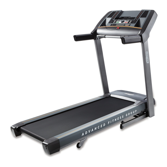
- Page 2 Product Browse 5.5AT...
- Page 3 Product Browse 5.9AT...
-
Page 4: Table Of Contents
Contents CHAPTER 1: SERIAL NUMBER LOCATION......................CHAPTER 2: CONSOLE INSTRUCTION 2.1 Console Operation..............................7 2.2 Display Window..............................2.3 Getting Started................................ 8 2.4 Workout Profiles..............................9 2.5 Target Profiles.................................9 2.6 Reset The Console............................... 10 2.7 Finishing Your Workout............................10 2.8 Using Your CD/MP3 Player..........................10 2.9 AFG TABLET CONNECTED FITNESS SYSTEM (5.7AT &... - Page 5 CHAPTER 6: PART REPLACEMENT GUIDE 6.1 Motor Replacement............................6.2 Rear Roller Replacement..........................6.3 Side Rail Replacement............................6.4 Running Deck Replacement..........................6.5 Front Roller Replacement..........................6.6 Running Belt Replacement..........................6.7 Motor Control Board (MCB) Replacement..................... 6.8 Drive Belt Replacement............................. 6.9 Incline Motor Replacement..........................6.10 Console Replacement.............................
-
Page 6: Chapter 1: Serial Number Location
CHAPTER 1: Serial Number Location SERIAL NUMBER... -
Page 7: Chapter 2: Console Instruction
CHAPTER 2: Console Instruction 2.1 CONSOLE OPERATION Note: There is a thin protective sheet of clear plastic on the overlay of the console that should be removed before use. A) LED DISPLAY WINDOWS: time, distance, calories, heart rate, speed, and incline. B) TARGET LED INDICATORS: indicate what target (if any) is set for the current program. -
Page 8: Display Window
CHAPTER 2: Console Instruction 2.2 DISPLAY WINDOWS TIME: Shown as minutes : seconds. View the time remaining or the time elapsed in your workout. DISTANCE: Shown as miles. Indicates distance traveled or distance remaining during your workout. SPEED: Shown as MPH. Indicates how fast your walking or running surface is moving. INCLINE: Shown as percent. -
Page 9: Workout Profiles
CHAPTER 2: Console Instruction 2.4 WORKOUT PROFILES 1) MANUAL: Adjust your speed and incline manually during your workout. 2) INTERVALS: Improves your strength, speed and endurance by increasing and decreasing the speed throughout your workout to involve your heart and other muscles. Includes 10 levels. Speed changes and segments repeat 90 seconds and 30 seconds 3) WEIGHT LOSS: A workout designed specifically to target fat. -
Page 10: Reset The Console
CHAPTER 2: Console Instruction burned are calculated using weight input of user profile. 2.6 RESET THE CONSOLE Hold STOP key for 3 seconds. 2.7 FINISHING YOUR WORKOUT When your workout is complete, the unit will beep. Your workout information will stay displayed on the console for 30 seconds and then reset. -
Page 11: Chapter 3: Electric Connection System
CHAPTER 3: Electrical Connection System 3.1 ELECTRICAL DIAGRAM 5.5AT Console Wire... - Page 12 CHAPTER 3: Electrical Connection System 5.5AT Console Wire 5.5AT USB Wire Function Function VBUS1 IGND RIGHT USB_DP USB_DM LED CTL1 LED CTL2 LEFT...
- Page 13 CHAPTER 3: Electrical Connection System Console wire...
-
Page 14: Ucb Circuit Board Instruction
CHAPTER 3: Electrical Connection System USB Connector Wire 3.2 UCB CIRCUIT BOARD INSTRUCTIONS LED1 speed LED2 Incline LED3 Weight loss LED4 LED5 interval LED6 distance LED7 bluetooth LED8 calories... -
Page 15: Mcb Circuit Board Instruction
CHAPTER 3: Electrical Connection System 3.3 MCB CIRCUIT BOARD INSTRUCTIONS 5.5AT MCB Power line Incline motor power connector Console cable connector Speed sensor connector Drive motor connector... - Page 16 CHAPTER 3: Electrical Connection System 3.3 MCB CIRCUIT BOARD INSTRUCTIONS 5.9AT MCB Power Line Incline motor power cable Speed sensor cable Console set cable Software burning cable Drive motor cable MCB LED Configure...
-
Page 17: Chapter 4: Engineering Mode
CHAPTER4: Engineer Mode Press incline ▲ and speed ▼3 seconds at the same time to enter ENG mode. 1) You can clockwise rotate “push to select” to select ENG mode; 2) You can press “▲/▼” to select ENG mode;... - Page 18 CHAPTER4: Engineer Mode...
-
Page 19: Chapter5: Troubleshooting
CHAPTER5: Troubleshooting 5.1 Error Code List Mode Name Error Code Description 5.5AT RPM was not detect Sudden accelerate 5.9AT TROUBLESHOOTING – NO POWER TO THE CONSOLE 1) SYMPTOM: a. Turn on the power switch, but the console will not light up. 2) SOLUTION: Please note the MCB in this model does NOT have an LED indicating the power is on. -
Page 20: No Function For Safety Key
CHAPTER 3: Troubleshooting 5.3 TROUBLESHOOTING – NO FUNCTION FOR SAFETY KEY SYMPTOM: a. The safety key inserted in console, but display window still shows “safety key off”. SOLUTION: a. Check if the safety key totally inserted in the console. - If no, take off and insert again. b. -
Page 21: Incline Motor Issues
CHAPTER 5: Troubleshooting 5.5 TROUBLESHOOTING - INCLINE MOTOR ISSUES SYMPTOM: The incline motor does not lift up or down. SOLUTION: Enter Engineering Mode, and scroll to ENG 1 (Hardware Test). Press the key “ENTER” first and then the key ”START”. Press the key “INCLINE ▲/▼”. - Page 22 CHAPTER 5: Troubleshooting 5.6 TROUBLESHOOTING - NOISE ISSUES-CONTINUED if needed. - Check the front and rear rollers, replace if needed. c. This sound is likely caused by the optic disk. - Check that the optic disk is tight on the motor and not rubbing the speed sensor. d.
-
Page 23: Heart Rate Function Issue
CHAPTER 5: Troubleshooting 5.7 TROUBLESHOOTING- HEART RATE FUNCTION ISSUE 1) SYMPTOM: a. The chest strap being used is not making good contact with the user's chest. b. The chest strap is at a low battery status. c. The chest strap is damaged. d. -
Page 24: Speaker / Audio Issues
CHAPTER 5: Troubleshooting 5.8 TROUBLESHOOTING - SPEAKER / AUDIO ISSUES-CONTINUED - If the speaker board, amp board, wiring, and speakers do not solve the issue, replace the console. b. There is a bad connection between the headphones and the console. - Verify the connection of the music player to the dock or audio adaptor cable. -
Page 25: Chapter 6: Part Replacement Guide
CHAPTER 6: Part Replacement Guide MOTOR REPLACEMENT 1) Remove the 4 screws holding the motor cover to the frame (Fig-1). 2) Pull up the cover from frame (Fig-2) Fig-1 Fig-2 3) Fig-3 shows the motor area with the motor cover removed. Fig-3 4) Reverse Steps 1-3 to install a new motor cover. -
Page 26: Rear Roller Replacement
CHAPTER 6: Part Replacement Guide REAR ROLLER REPLACEMENT 1) Remove the rear end caps 2) Remove both roller adjustment screws (Fig-2&Fig-2). Fig-1 Fig-2 3) Remove the roller... -
Page 27: Side Rail Replacement
CHAPTER 6: Part Replacement Guide SIDE RAIL REPLACEMENT 1) Remove the rear end cap (Fig-1 & Fig-2) Fig-1 Fig-2 2) Slide the rail off the back of the treadmill 3) Reverse Steps 1-2 to install a new side rail. NOTE: After reinstalling the side rail, make sure the rear end cap is on first before tightening the screws for proper gap spacing. -
Page 28: Running Deck Replacement
CHAPTER 6: Part Replacement Guide RUNNING DECK REPLACEMENT 1) Remove the motor cover as outlined in Section 4.1. 2) Remove the side rail as outlined in Section 4.3. 3) Remove the end cap in section 4.2 4) Remove the running deck screws (Fig-1). Fig-1 Fig-2 5) Remove the running deck from the running belt... -
Page 29: Front Roller Replacement
CHAPTER 6: Part Replacement Guide FRONT ROLLER REPLACEMENT 1) Remove the motor cover as outlined in Section 4.1. 2) Loosen both of the rear roller screws to remove tension from the running belt (Figure 1). Fig-1 5) Remove the drive belt from the front roller and remove the roller from the running belt. -
Page 30: Running Belt Replacement
CHAPTER 6: Part Replacement Guide RUNNING BELT REPLACEMENT 1) Remove the motor cover as outlined in Section 4.1. 2) Remove the rear roller as outlined in Section 4.2. 3) Remove the running deck as outlined in Section 4.4. 4) Remove the front roller as outlined in Section 4.5. 5) Remove the running belt (Fig-1). -
Page 31: Motor Control Board (Mcb) Replacement
CHAPTER 6: Part Replacement Guide MOTOR CONTROL BOARD (MCB) REPLACEMENT 1) Turn off power and disconnect the cord from the machine. 2) Remove the motor cover as outlined in Section 4.1. 3) Disconnect the wire connectors at the MCB. (Fig-1) 4) Remove the 2 screws holding each side of the MCB to the frame . -
Page 32: Drive Belt Replacement
CHAPTER 6: Part Replacement Guide DRIVE BELT REPLACEMENT 1) Turn off power to the treadmill and disconnect the power cord. 2) Remove the motor cover as outlined in Section 4.1. 3) Remove the front roller in section 4.5 4) Lift the roller and remove the old drive belt Fig-1 Fig-2 5) Install new drive belt and Reverse Steps 1-3.(Fig-1) -
Page 33: Incline Motor Replacement
CHAPTER 6: Part Replacement Guide INCLINE MOTOR REPLACEMENT 1) Turn off power to the treadmill and disconnect the power cord. 2) Remove the motor cover as outlined in Section 4.1 3) Lift the treadmill and support it so that the front wheels are off the floor. 4) Remove the screws from the elevation rack (Fig-1&2) Fig-1 &... -
Page 34: Console Replacement
CHAPTER 6: Part Replacement Guide 6.10 CONSOLE REPLACEMENT 1) Turn off power to the treadmill and disconnect the power cord. 2) Remove the screws holding the console form heart rate bars 3) Remove the screws holding the console from the console mast. 4) Remove the console from the console frame.
Need help?
Do you have a question about the AFG Series and is the answer not in the manual?
Questions and answers