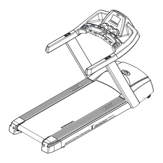
Johnson T8000 Service Manual
Hide thumbs
Also See for T8000:
- Owner's manual (24 pages) ,
- Owner's manual (13 pages) ,
- Service manual (62 pages)
Table of Contents
Advertisement
Quick Links
Advertisement
Table of Contents
Troubleshooting

Related Manuals for Johnson T8000


Summary of Contents for Johnson T8000
-
Page 1: Service Manual
JOHNSON T8000 Treadmill Service Manual Make by JearyCheng, KevinChang Aug.25.2004... - Page 2 TABLE OF CONTENTS SECTION 1: LIMITED WARRANTY……………………………………..1-1 SECTION 2: EXPLODED DIAGRAM…………………………………….2-1 SECTION 3: WIRING DIAGRAM…………………………………………3-1 SECTION 4: TROUBLE SHLOOTING…………………………………...4-1 SECTION 5: PARTS REPLACEMENT……………………………………5-1 SECTION 6: PREVENTIVE MAINTENANCE…………………………...6-1 APPENDIX : RECOMMENDED TOOLS Make by JearyCheng, KevinChang Aug.25.2004...
- Page 3 SECTION 1 LIMITED WARRANTY Comments and Questions………...………..……..………...1-2 Scope of Warranty…………………….…...…………1-2 Intended Use………………………..……..….……….1-2 Warranty Period………..………..…………….1-3 Defects Replacement…………………………...………….1-3 Safety Stock of Warranty Parts………………………..1-3 Warranty Procedure………………..………………..1-3 Technical Support..............1-4...
-
Page 4: Limited Warranty
Limited Warranty Johnson Health Technology Company and its employees are committed to providing our customers with the state-of-art designed and manufactured fitness equipment. This Limited Warranty and Service Procedure states JHT’s warranty policy and warranty procedures. We welcome comments and questions regarding our products. Please contact us at... - Page 5 Generally, if not otherwise specified, JHT provides one and a half year warranty for all JHT products starting from the date of production. Warranty coverage for each product will be detailed in the respective product owner’s manual. The distributor should send out the replacement parts without charge within 24 hours for any customer’s warranty claim due to defects of JHT workmanship or materials and the defects occurs during the warranty period.
- Page 6 defective electronics back to JHT in a routine basis (monthly is preferred). Fill out the warranty claim form and send it to JHT. Defective motors: The distributor may choose by himself the disposition of the failed motors under warranty. You can either send the motors to your local motor manufacturer’s authorized dealer for repair or you can remove the name plate, attaching a label on it to identify the failure symptom and send it back to JHT on a routine basis (monthly is preferred).
- Page 7 SECTION 1 WIRING DIAGRAM INSTRUCTION...
- Page 8 WIRING DIAGRAM (MCB-220V)…T8000 T1-----Motor wire (black) T2-----Motor wire (red) T3----- CE (N3 of Capacitor) Non CE (D1 of on/off switch) T4-----CE (N4 of Capacitor) Non CE (D3 of on/off switch) T5-----8-pin console cable T6-----6-pin console cable T7----- Elevation cable T8-----Speed sensor cable...
- Page 9 SECTION 2 CONSOLE ENGINEERING MODE GUIDE...
- Page 10 Engineering mode (T8000) 1.Hold both incline “↑” and speed “+” at the same time about 3sec to get into the engineering mode. The display will show “ENGINEERING MODE” Hold UP&FAST Key 3's PO : LOW SPEED LEARN MODE to previous Parameter...
- Page 11 Model Unit Min Speed Max speed 0.8K 20.0K T8000 0.5M 12.0M Address Description Default Value Min Value Max Value low speed learn mode hige speed learn mode middle speed learn mode low elevation learn mode hige elevation learn mode unit...
- Page 12 SECTION 3 MCB LED INSTRUCTIONS...
- Page 13 MCB LED Indication When we designed the lower control board (MCB) for our treadmills we placed status lights (LEDs) on it to aid in field Note: diagnosis and repair. The following is an overview of what Use a multi-meter these indicator lights mean and what can be checked with to test the power them in the field.
- Page 14 MCB LED Indication MOTOR Light- When lit, indicates the High Power Direct Current supply for the motor (B+) is online. This light will remain lit for a period of time after power has been removed from the MCB. While the MTR light remains lit, anyone handling the MCB should use caution since there is still a hazardous potential present.
- Page 15 MCB LED Indication Note: the incline is Light- Indicates the PCB is commanding the being incline motor to move up. If the User is commanded up commanding the incline to increase and this light is not lit, check cabling, verify proper PCB operation and replace it if either is defective.
- Page 16 MCB LED Indication Note: MTR_SHRT MOTOR short circuit of the MCB bad Light- Indicates the MOTOR short circuit, If the running belt not running at the MTR_SHRT LED light, express the MOTOR short circuit of the MCB bad.
- Page 17 MCB LED-AIDED TROUBLESHOOTING CHART PROBLEM/RESULT CORRECTIVE ACTION Verify connections, power switch, circuit No operation of MCB or PCB breaker and fuse No operation of MCB or PCB Check fuse F1 PCB will not power up Replace MCB or 6-pin console cable Verify adequate line voltage.
- Page 18 SECTION 4 TROUBLESHOOTINGS...
- Page 19 No display on console Possible causes: 1. Breaker is damaged. 2. ON/OFF switch is damaged. 3. MCB is damaged. 4. 6-pin console cable is damaged. 5. PCB is damaged. Fix: 1. ( refer to “MCB LED layout & indication”……SECTION 6) Verify if LED 220vAC(AC) is lit.
- Page 20 Running speed is not stable Possible causes: 1. AC power voltage is too low. 2. Tension of poly belt or running belt is too loose. 3. Poor adjustment of MCB. 4. MCB is damaged. 5. Motor is damaged. Fix: 1. Check the power voltage by using voltage-meter to see if it is within 230V±15%.
- Page 21 Treadmill starts to run by itself Possible causes: 1. The console cable is broken. 2. PCB is out of order. 3. MCB is out of order. Fix: 1. Replace the console cable with a new one. 2. Replace the PCB. 3.
- Page 22 Noises generated under motor cover Possible causes: 1. The running belt tension is adjusted too tight. 2. The bearing of front roller is not installed correctly. 3. Dirty grooves of poly belt. 4. The motor is damaged. Fix: 1. Adjust the belt tension so that the belt does not start slipping and then check if the noise has...
-
Page 23: Treadmill Will Not Start
Treadmill will not start Possible causes: 1. MCB is damaged. 2. 8-pin console cable is damaged. 3. PCB is damaged. 4. Motor is damaged. Fix: Open motor cover, verify wire connection MTR1 and MTR2 on the MCB then plug in the power cord and turn on the power switch. Then press “START“... - Page 24 Incline function does not work Possible causes: 1. The 8-pin console cable is damaged. 2. Incline motor is damaged. 3. PCB is damaged. 4. MCB is damaged. 5. The incline setting is not correct. Fix: Enter to the Engineering Mode to recalibrate the elevation values Then press "FAST"...
- Page 25 Speed or Incline Changes by Itself Possible causes: 1. Keypad is damaged. 2. PCB is damaged. Fix: 1. Remove the keypad and verify it is stuck. If it is, replace with a new keypad. 2. If speed or incline changes by itself, replace the PCB with a new one and refer to "Engineering Mode Guide"...
- Page 26 Error Messages on the Console When the Error Messages on the Console the lamp will be lighted in red Error-message Problem / Result The speed sensor can’t sense the speed. Press start and after 10 sec. the LED display will show 1.The incline motor was broken or the cable was lost.
- Page 27 Error Message " E1" Possible cause: speed sensor cable damaged. MCB is damaged. Check the magnet on the front roller. Fix: 1. Check the connector condition of the speed sensor cable. 2. Check the speed sensor wire not to touch the P1 of the MCB. 3.
- Page 28 T8000 maintenance lamp Maintenance lamp 1. When the distance accumulate to 2000KM the lamp will be lighted in blue. 2. There has to do some maintenance 2.1 Test the running belt if loose or not? 2.2 Lubricate the running belt 2.3 Remove the motor cover and clean the dust inside...
- Page 29 Heart-Rate-Control function does not work Possible causes: 1. Transmitter does not contact with user's chest very well. 2. Transmitter(Polar-belt) is at low battery status. 3. Transmitter(Polar-belt) is damaged. 4. Heart-rate-control board is damaged. 5. PCB is damaged. Fix: 1. Center the transmitter on your chest below the pectoral muscle(breast) as shown, then check again.
- Page 30 SECTION 7 PARTS REPLACEMENT PROCEDURE...
- Page 31 MCB REPLACEMENT Tools required: Philips screwdriver Procedure: 1. remove the motor cover 2. Unplug all the cables and wires connecting to the MCB. 3. With the screwdriver remove the MCB. 4. Replace the MCB and tighten the screws holding the MCB to the frame. 5.
- Page 32 PCB REPLACEMENT Tools required: Philips screwdriver Procedure: 1. Loose the screws of the console lower cover. 2. Loose the screws of the console display.
- Page 33 3. Disconnect the plug of PCB from console then with the screwdriver remove the PCB. 4. Replace the PCB with a new one. 5. Reverse step 1-4 to install all parts.
- Page 34 KEYPAD REPLACEMENT Tools required: Screwdriver Procedure: 1. remove screws from the console upper cover. 2. Disconnect the plug of the keypad from the PCB. 3. Remove the overlay and the tape residue on the console thoroughly 4. Replace the keypad and plug the new keypad with the PCB. 5.
- Page 35 RUNNING BELT/DECK/ROLLER REPLACEMENT Tools required: Philips screwdriver T-handle key (6 mm, 5 mm) Procedure: 1. Remove the end capes of the side rail and pull out the two side rails. 2. Remove the motor cover. 3. Turn the flywheel counterclockwise by using your left hand and pull the drive belt out from the pulley of the front roller by using your right hand.
- Page 36 RUNNING BELT/DECK/ROLLER REPLACEMENT Tools required: Philips screwdriver T-handle key (6mm,5mm) Procedure: 8. Turn the flywheel counterclockwise by using your left hand and pull the drive belt out from the pulley of the front roller by using your right hand. 9. Loosen the screws from the front and rear rollers, remove the front roller and rear roller.
- Page 37 18. Install the front / rear rollers. Adjust the running belt tension screw to center the running belt at high speed. 19. Try to step on the belt at low speed to check if the belt slips. 20. Install the side rails and secure the end plates and all the covers.
-
Page 38: Motor Replacement
MOTOR REPLACEMENT Tools required: Philips screwdriver T-handle wrench (14mm) Ratchet Box Wrench (11mm) Procedure: 1. Remove top motor cover and bottom motor cover. 2. Remove cables connecting to the motor and the lower board, Meanwhile, remove the ground wire 3. Using your thumb to press the surface of belt and at the same time rotate the pulley in counter-clockwise till the poly belt being removed. - Page 39 INCLINE MOTOR REPLACEMENT Tools required: Philips screwdriver Wrench (14mm) Wrench ( 17mm) Procedure: 1. Remove screws of both top and bottom motor covers by using a screwdriver 2. Disconnect cables from the connectors of the incline motor and MCB and also disconnect the ground wire.
-
Page 40: Console Cable Replacement
CONSOLE CABLE REPLACEMENT Tools required: Philips screwdriver Procedure: 1. Remove the console lower cover and the motor cover . 2. Disconnect the console cable from the PCB and MCB. 3. Tie the old cable to the new one with a rigid string. - Page 41 MOTOR BEARINGS & CARBON BRUSH REPLACEMENT Tools required : Nutdriver (10mm, 11mm) Bearing puller Wooden-hammer Procedure: 1. Remove the carbon brush cover and spring. 2. Check if the surface of carbon brush is smooth. If the surface of carbon brush is pitted, rough, or with burn marks replace the carbon brush.
- Page 42 MOTOR BEARINGS & CARBON BRUSH REPLACEMEN Tools required: Nutdriver (10mm, 11mm) Bearing puller Wooden-hammer Procedure: 6. Remove the bearings at both sides of the shaft by using bearing puller. 7. Install the new bearings to the shaft by using wooden-hammer. 8.
- Page 43 SECTION 8 SERVICE FORM Revision: 1.0 Date: 1999-09-01...
- Page 44 MCB LED Status Report Product Type :....... Serial Number :......When power-up the treadmill the MCB LED status is : AC(*115V)Light 18V Light 11(*12)V Light LED On : LED On : LED On : LED Off : LED Off : LED Off : MTR Light I-Limit Light...
- Page 45 Field Failure Report Name of Distributor :…………………… Report # …………………..Warranty ( ) Yes ( ) No Failure ( ) Intermittent ( ) Persistent Product : ……………………… Serial number: ……………….. Failure Symptom : ( Pls refer to the service manual for the symptom of failure.
- Page 46 Parts Order Distributor:………………..….. Order # …………………………… Delivery Terms: ( ) CIP ..... Delivery Address: ( ) FCA ............................................Warranty ( ) Yes ( ) No Product Serial number ..................................................................Product Drawing # Part Number Part Name ......
- Page 47 Warranty Claim Form Claim no: ......Dealer Name: ..........Page ..of ...Pages MODEL SERIAL NUMBER DESCRIPTION OF DEFECT PARTS # AUTHORIZED BY: ......Revision: 1.0 Date: 1999-09-01...
Need help?
Do you have a question about the T8000 and is the answer not in the manual?
Questions and answers
Tread mill goes for a while then stops when you shake circuit board under neath display it goes again
The Johnson T8000 treadmill may stop intermittently when the circuit board under the display is shaken due to a faulty or loose connection in the keypad connecting plug, a damaged keypad, or a damaged PCB. Possible fixes include disconnecting and properly reconnecting the keypad, replacing the keypad, or replacing the PCB.
This answer is automatically generated